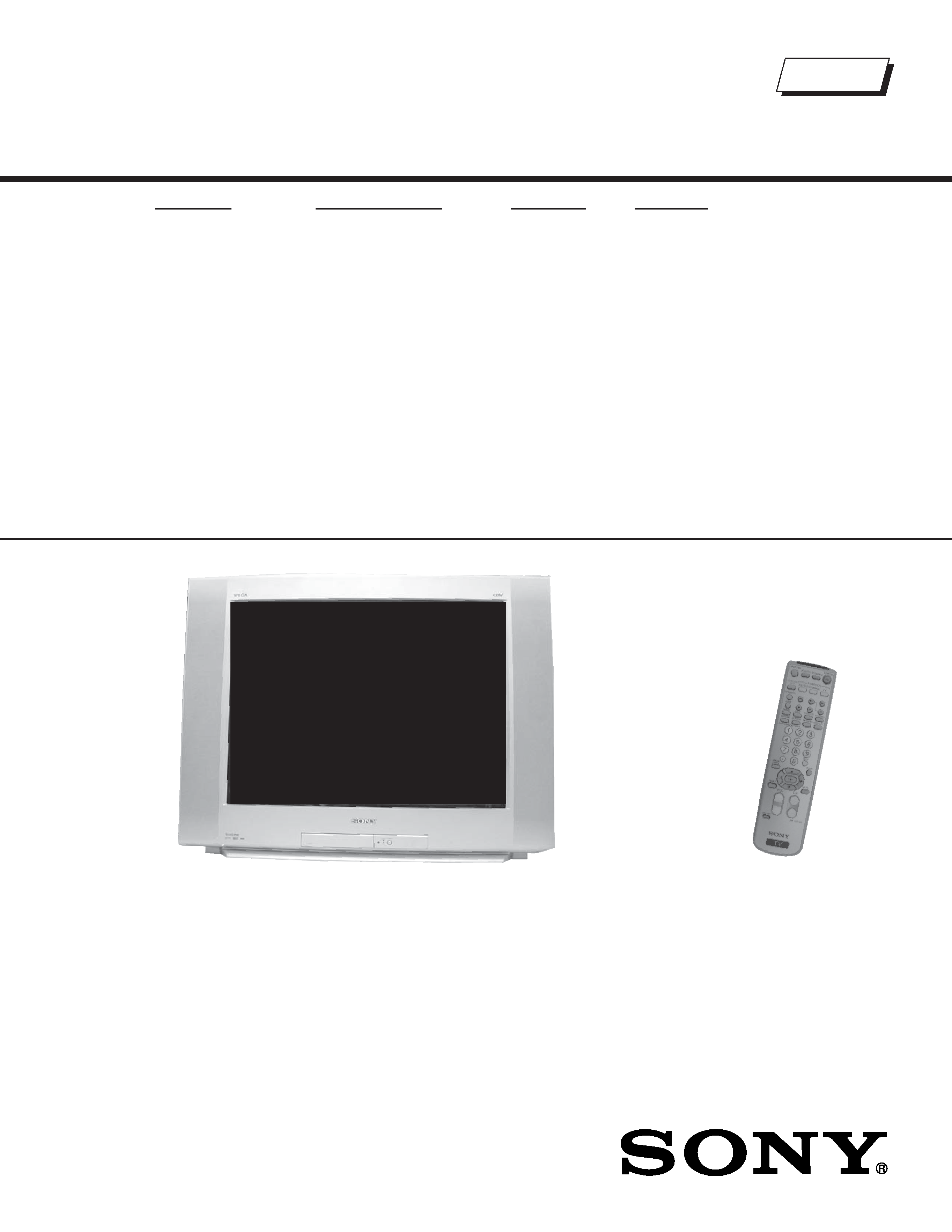
TRINITRON
® COLOR TELEVISION
SERVICE MANUAL
BA-6 CHASSIS
MODEL NAME
REMOTE COMMANDER
DESTINATION
CHASSIS NO.
9-965-983-01
KD-32FS130
RM-YD001
US
SCC-S61V-A
KD-36FS130
RM-YD001
US
SCC-S61W-A
HISTORY INFORMATION FOR THE FOLLOWING MANUAL:
ORIGINAL MANUAL ISSUE DATE: 6/2005
REVISION DATE
SUBJECT
6/2005
No revisions or updates are applicable at this time.
TRINITRON
® COLOR TELEVISION
SERVICE MANUAL
BA-6 CHASSIS
MODEL NAME
REMOTE COMMANDER
DESTINATION
CHASSIS NO.
9-965-983-01
KD-32FS130
RM-YD001
US
SCC-S61V-A
KD-36FS130
RM-YD001
US
SCC-S61W-A
Self Diagnosis
Supported model
KD-32FS130
RM-YD001

KD-32FS130/36FS130
KD-32FS130/36FS130
3
TABLE OF CONTENTS
SECTION TITLE
PAGE
SECTION TITLE
PAGE
Specifications ................................................................................. 4
Warnings and Cautions .................................................................. 6
Safety Check-Out ........................................................................... 7
Self-Diagnostic Function................................................................. 8
SECTION 1: DISASSEMBLY............................................................... 10
1-1. Rear Cover Removal............................................................ 10
1-2. Chassis Assembly Removal................................................. 10
1-3. Service Position ....................................................................11
1-4. Picture Tube Removal.......................................................... 12
Anode Cap Removal Procedure .......................................... 12
Cable Wire Dressing ............................................................ 13
KD-32FS130 Models Only .............................................. 13
KD-36FS130 Models Only .............................................. 22
SECTION 2: SET-UP ADJUSTMENTS................................................ 29
2-1. Beam Landing ...................................................................... 29
2-2. Convergence........................................................................ 30
2-3. Focus ................................................................................... 31
2-4. Screen (G2).......................................................................... 32
SECTION 3: SAFETY RELATED ADJUSTMENTS............................. 33
3-1. X R530, R531 Confirmation Method (HV Hold-Down
Confirmation) and Readjustments........................................ 33
3-2. B+ Voltage Confirmation and Adjustment ............................ 33
SECTION 4: CIRCUIT ADJUSTMENTS.............................................. 34
4-1. Remote Adjustment Buttons and Indicators ......................... 34
4-2. Accessing the Service Adjustment Mode ............................. 34
4-3. Confirming Service Adjustment Changes............................. 35
4-4. White Balance Adjustments ................................................. 36
4-5. A Board Adjustments............................................................ 36
4-6. Service Data Lists ................................................................ 39
4-7. ID Map Table ........................................................................ 47
SECTION 5: DIAGRAMS..................................................................... 48
5-1. Circuit Boards Location ........................................................ 48
5-2. Printed Wiring Board and Schematic Diagram Information.. 48
5-3. Block Diagrams and Schematics ......................................... 49
Signal Flow Block Diagram .................................................. 49
A Board Schematic Diagram (1 of 2).................................... 50
A Board Schematic Diagram (2 of 2).................................... 51
MD Board Schematic Diagram............................................. 53
C Board Schematic Diagram................................................ 55
V Board Schematic Diagram................................................ 57
GS Board Schematic Diagram ............................................. 59
HS Board Schematic Diagram ............................................. 60
5-4. Semiconductors ................................................................... 61
SECTION 6: EXPLODED VIEWS ........................................................ 62
6-1. Chassis ................................................................................ 62
6-2. Picture Tube ......................................................................... 63
SECTION 7: ELECTRICAL PARTS LIST............................................ 64
KD-32FS130/36FS130
KD-32FS130/36FS130
4
SPECIFICATIONS
1) 1 Vp-p 75 ohms unbalanced, sync negative
2) Y: 1 Vp-p 75 ohms unbalanced, sync negative
C: 0.286 Vp-p (Burst signal), 75 ohms
3) Y: 1.0 Vp-p, 75 ohms, sync negative; PB: 0.7 Vp-p, 75 ohms;
PR Vp-p, 75 ohms.
4) 500 mVrms (100% modulation), Impedance: 47 kilohms
5) This specification is the maximum wattage.
Design and specifications are subject to change without notice.
KD-32FS130
KD-36FS130
Power Requirements
120V, 60Hz
120V, 60Hz
Number of Inputs/Outputs
Video
1)
33
S Video
2)
11
Y,PB, PR
3)
22
Audio
4)
55
Audio Out
11
RF
5)
11
Speaker Output (W)
10W x 2
10W x 2
Power Consumption (W)
In Use (Max)
185W
185W
In Standby (Max)
5)
<1W
<1W
Dimensions (W x H x D)
mm
898 x 696 x 576 mm
985 x 776 x 633 mm
in
35
3/8 x 27 3/8 x 22 5/8 in
38
3/4 x 30 1/2 x 24 7/8 in
Mass
kg
74 kg
103.2 kg
lbs
163.2 lbs
227.5 lbs
Manufactured under license from Dolby
Laboratories Licensing Corporation. Dolby
and the double-D symbol are trademarks of
Dolby Laboratories.
As an ENERGY STAR® Partner, Sony
Corporation has determined that this
product meets the ENERGY STAR®
guidelines for energy efficiency. ENERGY
STAR® is a U.S. registered mark.
SRS and the ( )® symbol are trademarks of
SRS Labs, Inc.
Manufactured under license from BBE Sound,
Inc. Licensed by BBE Sound, Inc. under USP
4638258, 5510752 and 5736897. BBE and BBE
symbol are registered trademarks of BBE
Sound, Inc.
WEGA, FD Trinitron and Steady Sound are registered
trademarks of Sony Corporation.

KD-32FS130/36FS130
KD-32FS130/36FS130
5
Television system
American TV standard, NTSC
ATSC Compliant 8VSB, ATSC (8VSB terrestrial)
ANSI/SCTE 07 2000; QAM on cable
(Does not include CableCARD functionality)
Channel coverage
Analog: VHF: 2-69/CATV: 1-125
Digital: VHF: 2-69/CATV: 1-135
Antenna
75-ohm external antenna terminal for VHF/UHF
Picture tube
FD Trinitron
®
tube
Visible screen size
32-inch picture measured diagonally (KD-32FS130 Only)
36-inch picture measured diagonally (KD-36FS130 Only)
Actual screen size
34-inch measured diagonally (KD-32FS130 Only)
38-inch measured diagonally (KD-36FS130 Only)
Supplied Accessories
Remote Commander RM-YD001
Two Size AA (R6) Batteries
Optional Accessories
TV Stand
SU-32FS2 for KD-32FS130
SU-36FS2 for KD-36FS130