1
SERVICE MANUAL
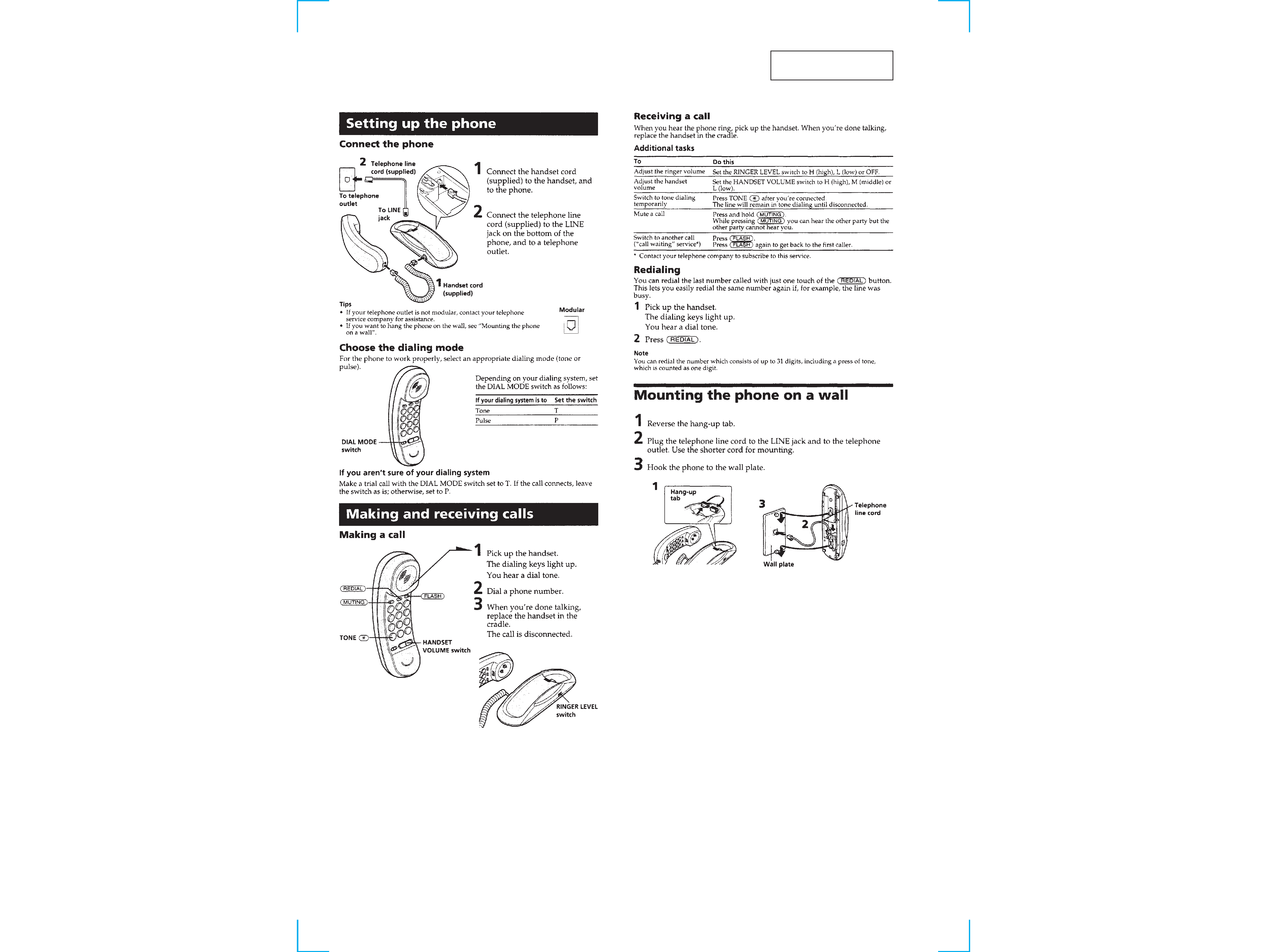
SPECIFICATIONS
Dial signal
Tone, 10 PPS (pulse) selectable
Dimensions
Approx. 69
× 74.5 × 225 mm (w/h/d)
(Approx. 2 3/4
× 3 × 8 7/8 inches)
Mass
Approx. 485 g
(Approx. 17 oz), attachments included
Supplied accessories
· Telephone line cords (2)
· Handset cord
Design and specifications are subject to change without notice.
IT-B1
Canadian Model
Central & South America Model
TELEPHONE
MICROFILM
Notes on Chip Component Replacement
· Never reuse a disconnected chip component.
· Notice that the minus side of a tantalum capacitor may be dam-
aged by heat.
Photo: WHITE Type
2
SECTION 1
GENERAL
This section is extracted
from instruction manual.
3
3
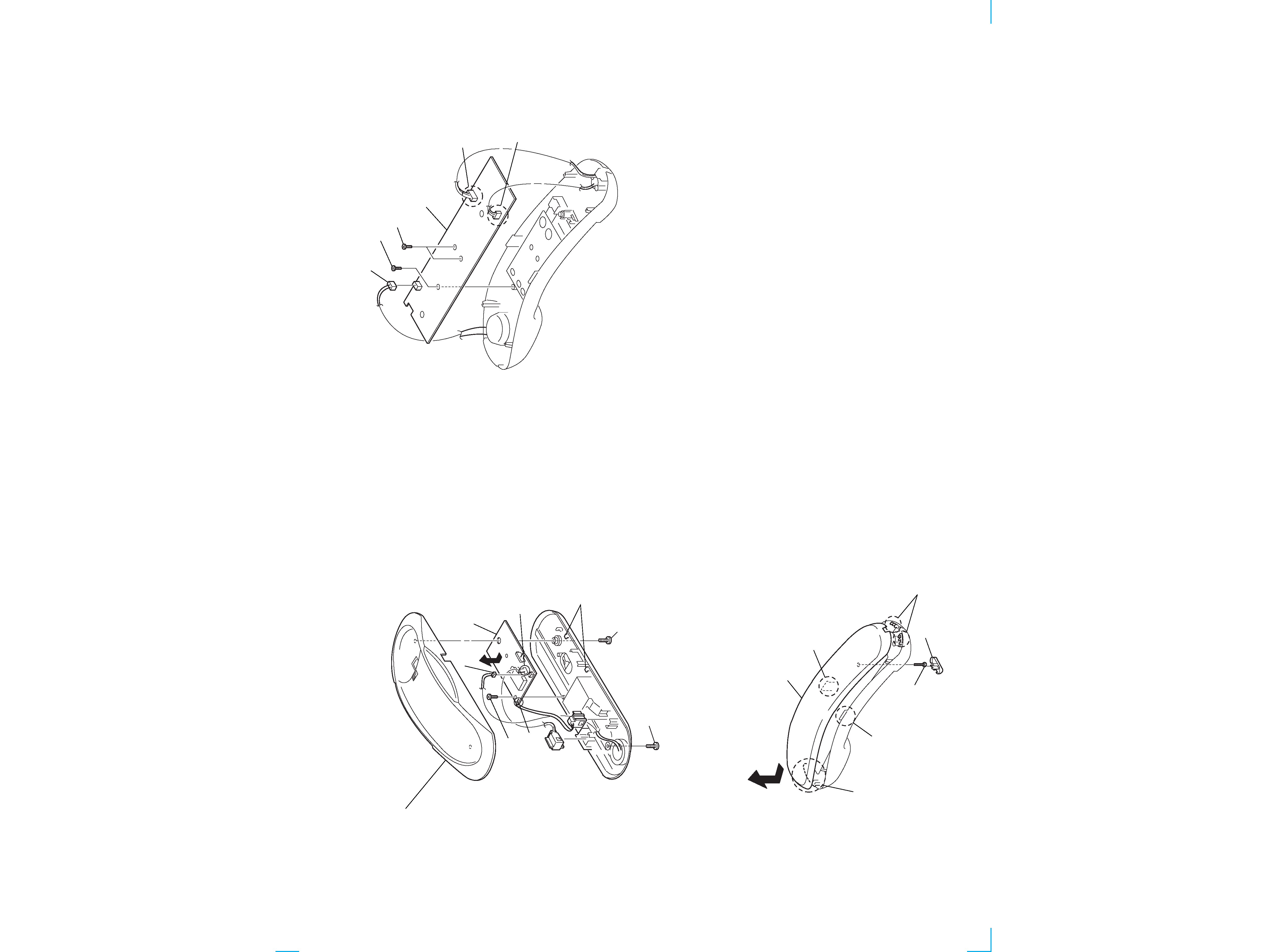
1 knob
3 claws
4 claw
8 handset (front)
5 claw
6 claw
7
2 P 2.6x16
1 CN5
2 BTP 2.6x6
3 BTP 2.6x6
5 Removal the solders.
6 Removal the solders.
4 HAND MAIN board
7 Removal the solders.
9 CRADLE board
8 Removal the solders.
claws
6
4 CN1
5 BTP 2.6x6
2 BTP 3x8
3 cabinet base (upper) assy
1 BTP 3x8
SECTION 2
DISASSEMBLY
Note : Follow the disassembly procedure in the numerical order given.
2-1. CRADLE BOARD
2-2. HANDSET (FRONT)
2-3. HAND MAIN BOARD
44
IT-B1
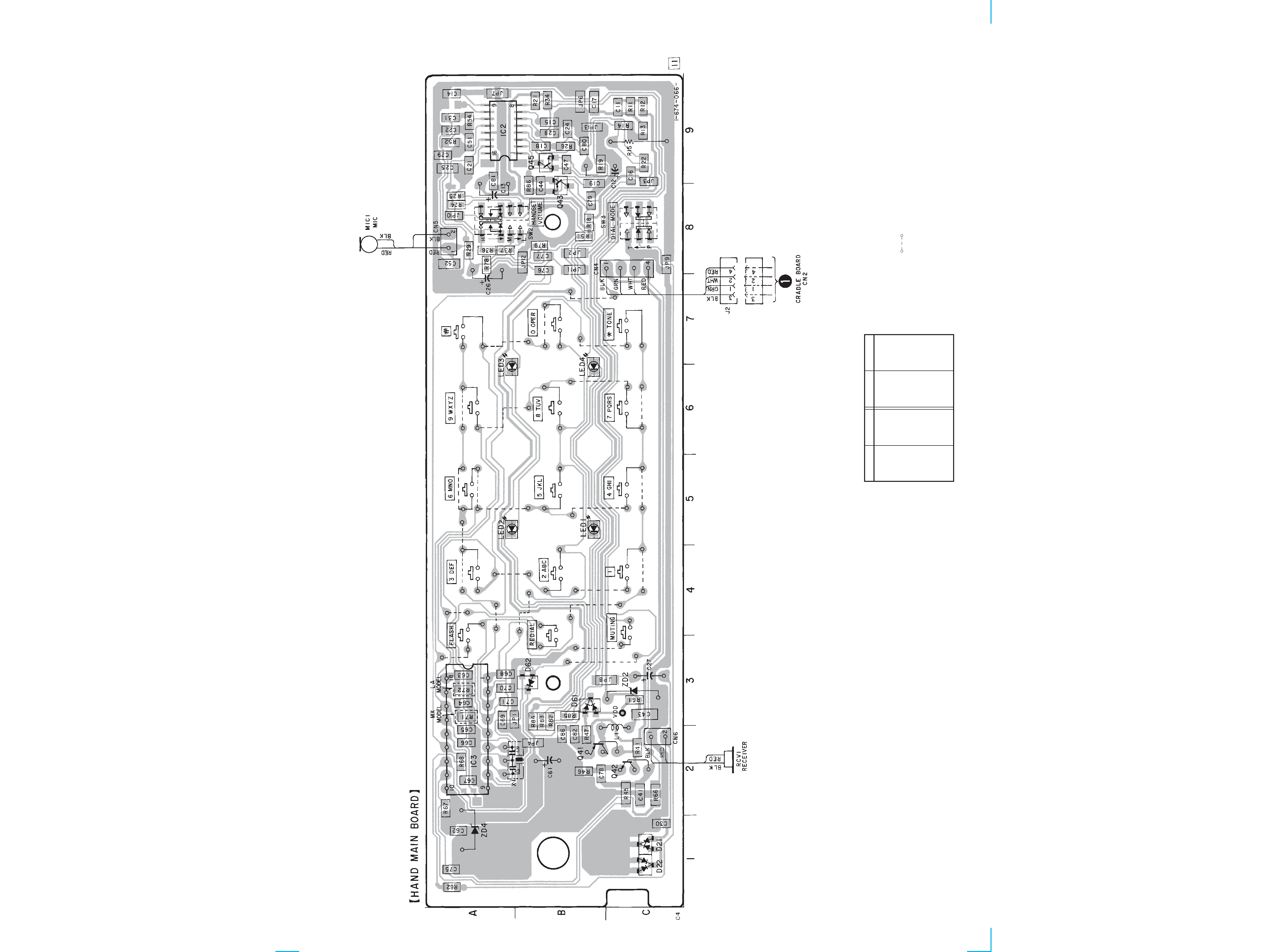
3-1. PRINTED WIRING BOARD -- HANDSET SECTION --
SECTION 3
DIAGRAMS
LED3
A-6
LED4
B-6
Q41
B-2
Q42
C-2
Q43
B-8
Q45
B-9
ZD2
C-3
ZD4
A-1
D21
C-1
D22
C-1
D61
B-3
D62
B-3
IC2
A-9
IC3
A-2
LED1
B-5
LED2
A-5
· Semiconductor Location
Ref. No.
Location
Ref. No.
Location
Note:
· X : parts extracted from the component side.
·
: Carbon pattern.
·
¢
: internal component.
· b : Pattern from the side which enables seeing.
(The other layer's patterns are not indicated.)
· Abbreviation
MX
: Mexican model
LA
: Latin American model
55
IT-B1
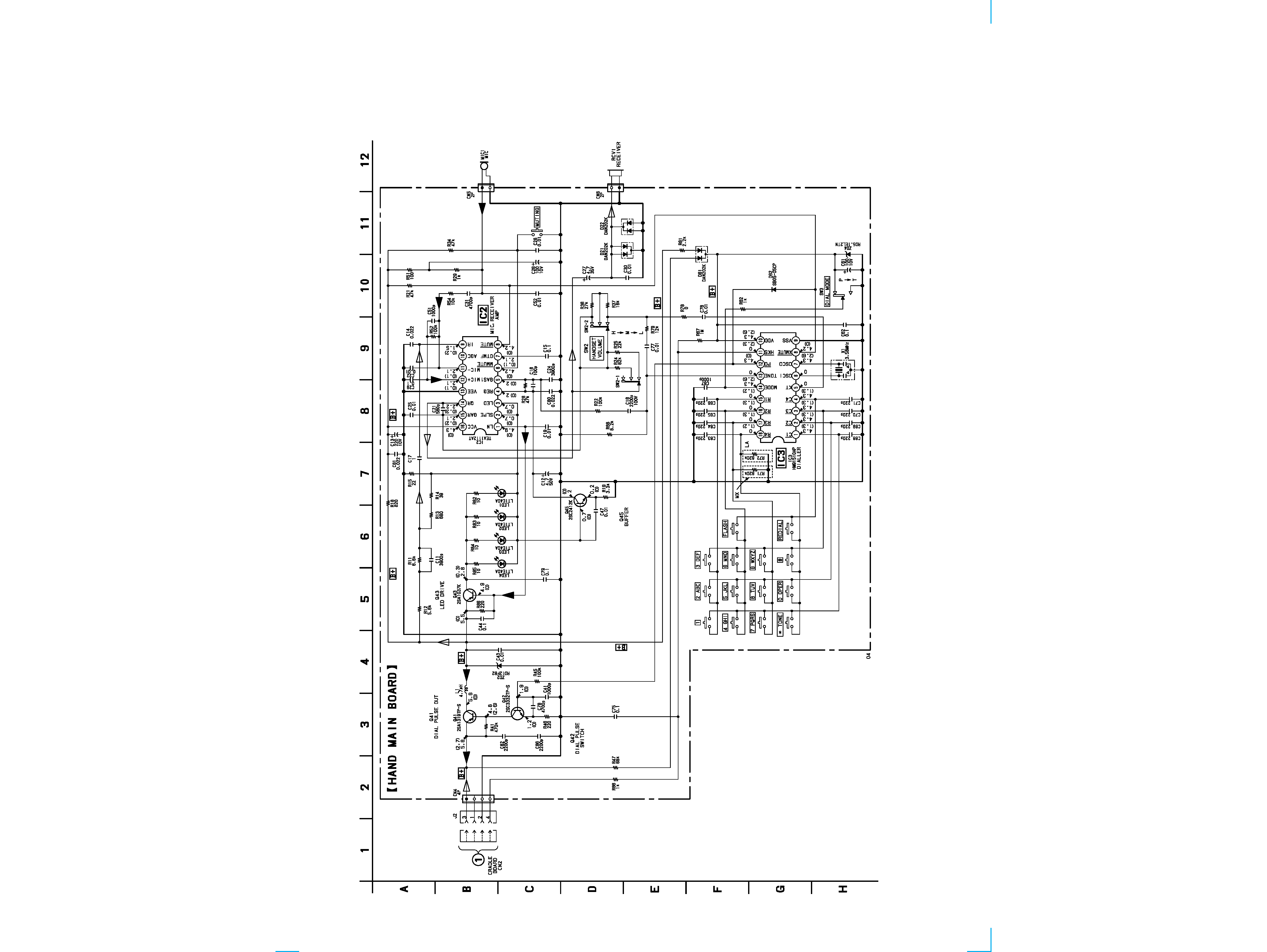
3-2. SCHEMATIC DIAGRAM -- HANDSET SECTION -- · Refer to page 7 for IC Block Diagrams.
Note:
· All capacitors are in µF unless otherwise noted. pF: µµF
50 WV or less are not indicated except for electrolytics
and tantalums.
· All resistors are in
and 1/4 W or less unless otherwise
specified.
·
%
: indicates tolerance.
·
¢
: internal component.
· C : panel designation.
· U : B+ Line.
· Connect J2 and J3 with handset cord.
Power voltage is dc 12V and fed with regulated dc power
supply from J3 with 100
in series.
· Voltage is dc with respect to ground under no-signal
condition.
no mark : OFF HOOK
(
) : ON HOOK
· Voltages are taken with a VOM (Input impedance 10 M
).
Voltage variations may be noted due to normal produc-
tion tolerances.
· Signal path.
N
: RX (from TEL LINE)
O
: TX (to TEL LINE)
P
: bell
· Abbreviation
MX
: Mexican model
LA
: Latin American model