ICF-M410L
AEP Model
SERVICE MANUAL
FM STEREO/MW/LW
PLL SYNTHESIZED RADIO
Sony Corporation
Personal Audio Company
Shinagawa Tec Service Manual Production Group
9-873-156-01
2001E1600-1
© 2001.5
SPECIFICATIONS
Ver 1.0 2001. 05
Speaker: 7.7 cm (31/8 inches) 8
Power output: 200 mW (at 10 % harmonic distortion)
Output: v (earphone) jack (ø3.5 mm minijack)
Power requirements: 4.5 V DC, three R6 (size AA) batteries
External power source: DC IN 4.5 V
Dimensions:
Approx. 205
× 104 × 40.5 mm (w/h/d)
(Approx. 8 1/3
× 4 1/8 × 1 5/8 inches) not incl. projecting
parts and controls
Approx. 212
× 104 × 42.5 mm (w/h/d)
(Approx. 8 3/8
× 4 1/8 × 1 11/16 inches) incl. projecting
parts and controls
Mass: Approx. 504 g (17.8 oz ) incl. batteries
Design and specifications are subject to change
without notice.

2
TABLE OF CONTENTS
ICF-M410L
Notes on chip component replacement
· Never reuse a disconnected chip component.
· Notice that the minus side of a tantalum capacitor may be
damaged by heat.
Flexible Circuit Board Repairing
· Keep the temperature of soldering iron around 270°C
during repairing.
· Do not touch the soldering iron on the same conductor of the
circuit board (within 3 times).
· Be careful not to apply force on the conductor when soldering
or unsoldering.
1. GENERAL ·································································· 3
2. DISASSEMBLY ························································· 4
3. ELECTRICAL ADJUSTMENTS ····························· 5
4. DIAGRAMS
4-1.
Block Diagram ····························································· 7
4-2.
Schematic Diagram ······················································ 8
4-3.
Printed Wiring Board ··················································· 9
4-4.
IC Pin Function Description ······································ 10
4-5.
IC Block Diagram ······················································ 10
5. EXPLODED VIEWS ················································ 11
6. ELECTRICAL PARTS LIST ·································· 12
3
ICF-M410L
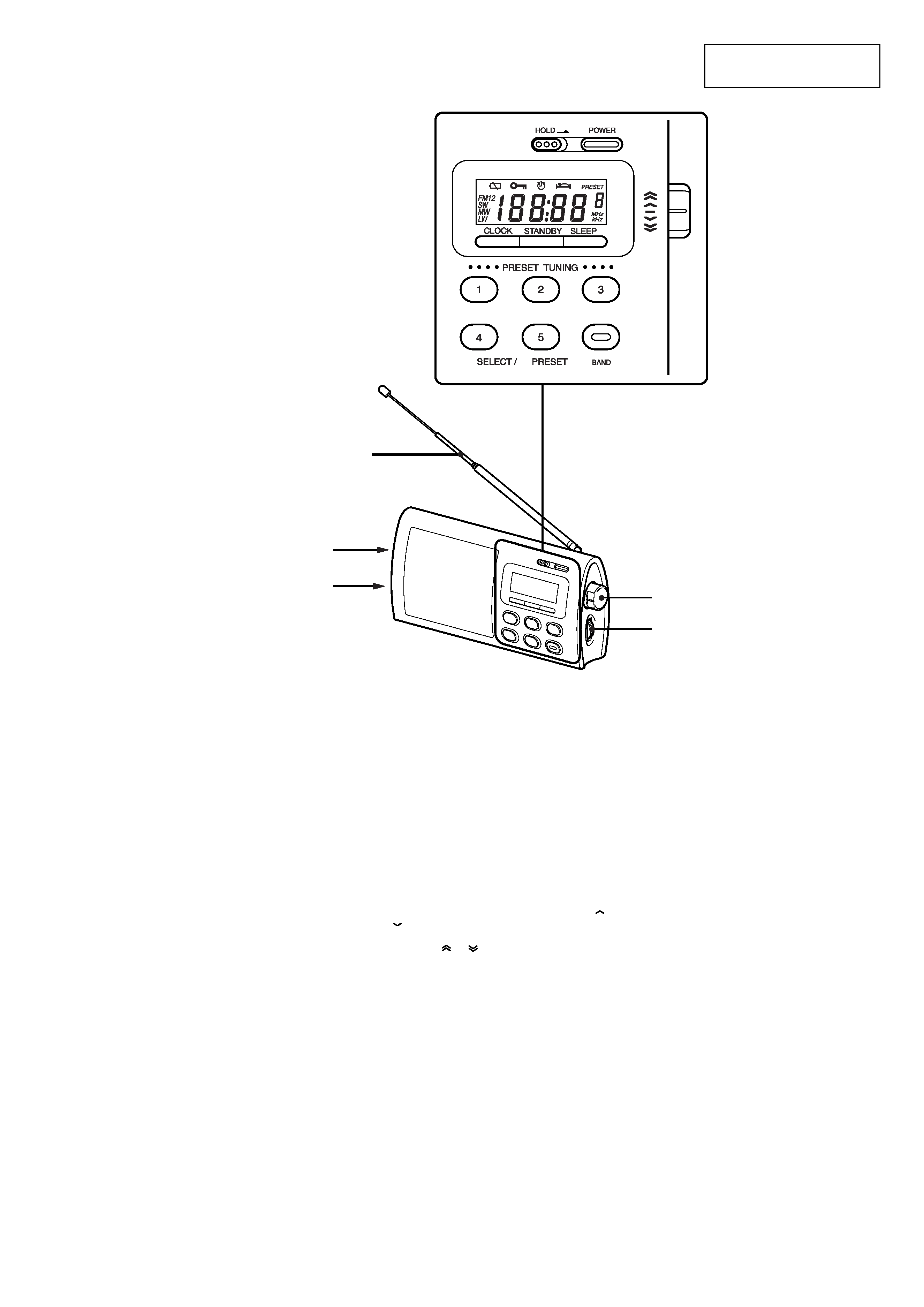
This section is extracted
from instruction manual.
SECTION 1
GENERAL
*
Telescopic Antenna
TUNE/TIME SET
VOL
DC IN 4.5V
v
jack
Setting the Clock
The display will flash "0:00" when the batteries are
installed or the AC power adaptor is plugged in for
the first time.
The clock can be adjusted when the radio is off.
1 To stop flashing of the display, press
CLOCK (mb/CLOCK for ICF-M410S).
2 While holding down CLOCK, turn
TUNE/TIME SET to set the clock to the
current time.
When you turn the control knob a little to
or
, the clock digits move forward or back one
by one, and when you turn the control knob
further to
or
, the clock digits move
rapidly.
When you release CLOCK, the clock starts
operating, and ":" starts flashing.
24-hour system : "0:00" = midnight, "12:00" =
noon
4
ICF-M410L
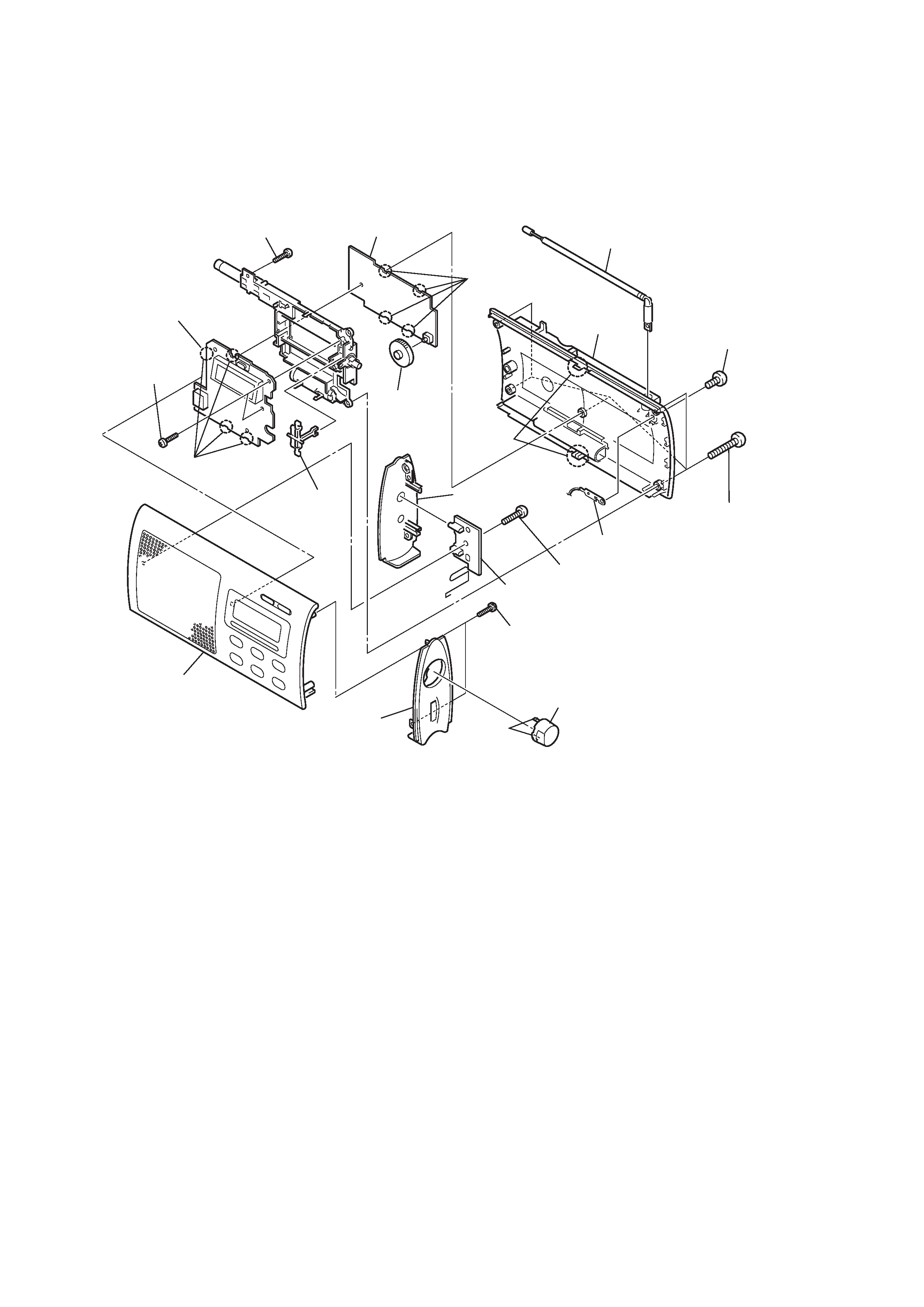
SECTION 2
DISASSEMBLY
Note :
Follow the disassembly procedure in the numerical order given.
9
Screw (+PTPWH 2
× 8)
1
Screw (+B 3
× 6)
3
Five screws
(+BTP 3
× 14)
q;
Two screws (+P 2
× 8)
qf
Two screws
(+P 2
× 8)
6
Screw (+PTPWH 2.6
× 8)
7
Side panel (L)
qs
Side panel (R)
qd
Arm (jog)
8
JACK board
qg
KEY board
qj
MAIN board
qh
Knob
2
Antenna, telescopic
Cabinet rear
4
Claws
qa
Claws
Remove the Claws
Remove the Claws
Knob (jog)
5
Plate, contact
Cabinet (front) sub assy
5
ICF-M410L
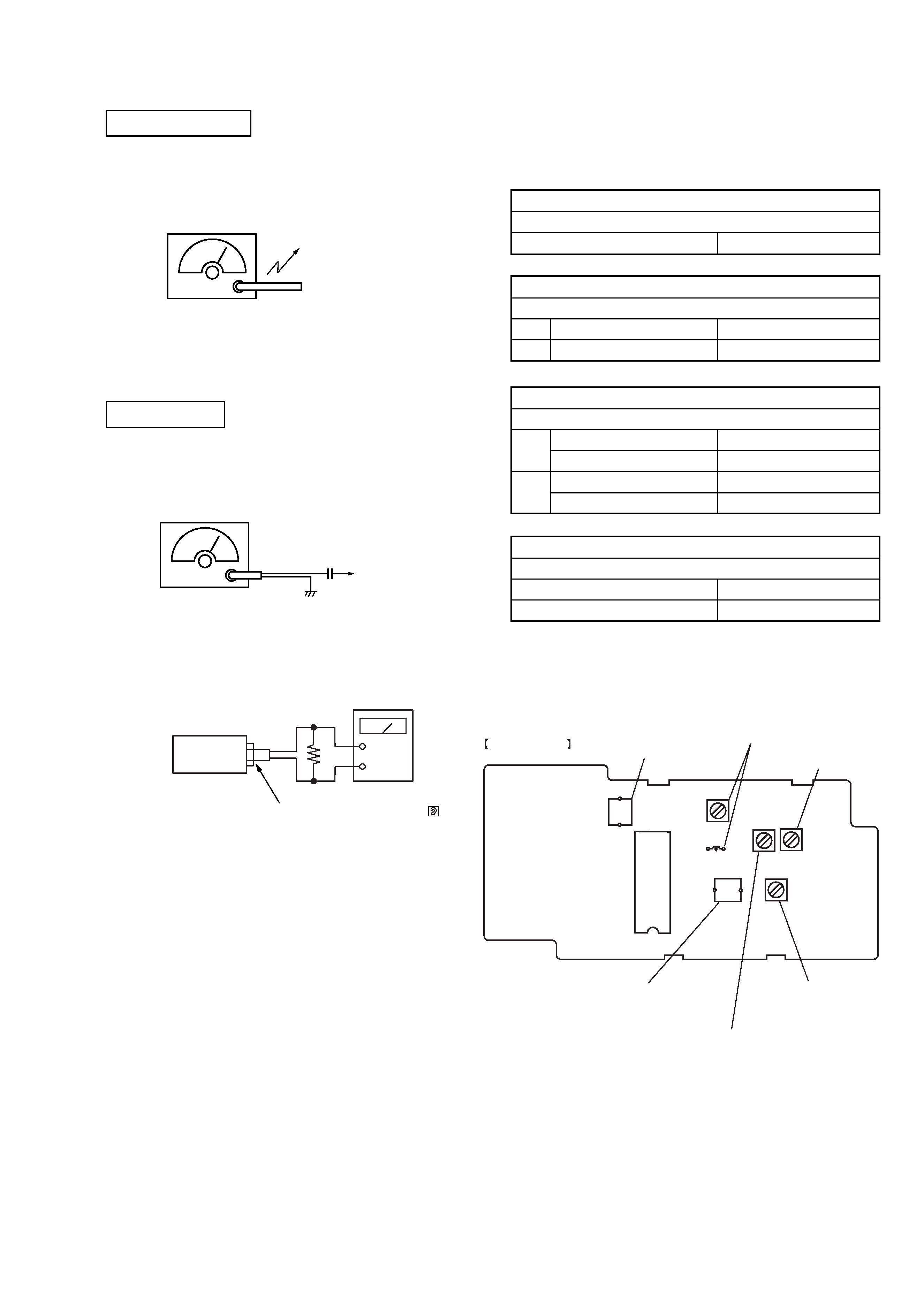
SECTION 3
ELECTRICAL ADJUSTMENTS
BAND : AM
· Repeat the procedures in each adjustment several times for the
maximum level meter indication.
· The frequency coverage and tracking adjustments should be finally
done by the trimmer capacitors.
MW/LW SECTION
FM SECTION
[Adjustment Location : Main board] (Component side)
Put the lead-wire
antenna close to
the set.
30% amplitude modulation by 400Hz
signal.
Output level : as low as possible
AM RF signal
generator
0.01
µF
FM RF signal
generator
telescopic
antenna
terminal
75kHz (100%) amplitude modulation
by 1kHz signal.
Output level : as low as possible
16
set
+
level meter
Speaker terminal (EPJ301)
AM IF ADJUSTMENT
Adjust for a maximum reading on level meter.
T15
450 kHz
FM TRACKING ADJUSTMENT
Adjust for a maximum reading on level meter.
L6
87.5 MHz
CT3
108 MHz
BAND : FM
MAIN BOARD
(Component side)
CT2
LW TRACKING
adjustment
CT4
LW FREQUENCY
COVERAGE
adjustment
L4
MW FREQUENCY
COVERAGE
adjustment
T1
AM IF
adjustment
L6,CT3
FM TRACKING
adjustment
CT1
MW TRACKING
adjustment
MW/LW TRACKING ADJUSTMENT
Adjust for a maximum reading on level meter.
LW
ANT102
162 kHz
CT2
243 kHz
MW
ANT102
603 kHz
CT1
1,404 kHz
MW/LW FREQUENCY COVERAGE ADJUSTMENT
Adjust for a maximum reading on level meter.
LW
CT4
153 kHz
MW
L4
531 kHz