SERVICE MANUAL
LCD-TV DVD KITCHEN CLOCK RADIO
US Model
SPECIFICATIONS
ICF-DVD57TV
Ver. 1.0 2005.04
Model Name Using Similar Mechanism
NEW
Optical Pick-up Block Name
KHM-310BAA
9-879-703-01
2005D05-1
© 2005.04
Sony Corporation
Personal Audio Group
Published by Sony Engineering Corporation
Manufactured under license from Dolby
Laboratories. "Dolby", "Pro Logic", and the
double-D symbol are trademarks of Dolby
Laboratories.
"DTS," "DTS Digital Surround" and "DTS
Digital Out" are trademarks of Digital Theater
Systems, Inc.
General
Time display
12-hour system
Speaker
77 mm (3
1/8 inches) dia,
6
Power outputs
1.8 W + 1.8 W (at 10%
harmonic distortion)
Power requirements
120 V AC, 60 Hz
Dimensions
Approx. 400
× 123 × 322.5
mm (w/h/d)
(Approx. 15
3/4
× 4 7/8 × 12 3/4
inches) incl. projecting
parts and controls
Mass
Approx. 4.8 kg (10 lb 9 oz)
Supplied accessories
Mounting screws (4),
Template (1),
Spacers (4),
Remote control (1)
Design and specifications are subject to change
without notice.
AUDIO POWER
SPECIFICATIONS
POWER OUTPUT AND TOTAL HARMONIC
DISTORTION
With 6ohm loads, both channels driven from
100 10 000 Hz; rated 1.4 W per channel-
minimum RMS power, with no more than 10
% total harmonic distortion in AC operation.
TV section
Television system
American TV standard/
NTSC
Channel coverage
VHF: 213/UHF: 1469/
CATV: 1125
Antenna
75-ohm external antenna
terminal for VHF/UHF
Screen type
Wide LCD color monitor
Size
9 inches
System
TFT active matrix
Number of dots
336,960 dots
Input
1 video, 1 audio
DVD/CD player section
Emission duration
Continuous
Laser output
Less than 1,000 µW
(This output is the value
measured at a distance of
about 200 mm from the
objective lens surface on
the optical pick-up block
with 7 mm aperture.)
Frequency response:
CD: 20 20,000 Hz +1/-1
dB
DVD Video: 20 22,000 Hz
+1/-1 dB
Wow and flutter:
Below measurable limit
Output
OPTICAL OUTPUT
Radio section
Frequency range
FM : 87.5 108 MHz
AM: 530 1,710 kHz
2
ICF-DVD57TV
CAUTION
Use of controls or adjustments or performance of procedures
other than those specified herein may result in hazardous radiation
exposure.
SAFETY-RELATED COMPONENT WARNING!!
COMPONENTS IDENTIFIED BY MARK 0 OR DOTTED LINE
WITH MARK 0 ON THE SCHEMATIC DIAGRAMS AND IN
THE PARTS LIST ARE CRITICAL TO SAFE OPERATION.
REPLACE THESE COMPONENTS WITH SONY PARTS WHOSE
PART NUMBERS APPEAR AS SHOWN IN THIS MANUAL OR
IN SUPPLEMENTS PUBLISHED BY SONY.
Notes on chip component replacement
· Never reuse a disconnected chip component.
· Notice that the minus side of a tantalum capacitor may be
damaged by heat.
Flexible Circuit Board Repairing
· Keep the temperature of the soldering iron around 270 °C
during repairing.
· Do not touch the soldering iron on the same conductor of the
circuit board (within 3 times).
· Be careful not to apply force on the conductor when soldering
or unsoldering.
SAFETY CHECK-OUT
After correcting the original service problem, perform the following
safety check before releasing the set to the customer:
Check the antenna terminals, metal trim, "metallized" knobs, screws,
and all other exposed metal parts for AC leakage.
Check leakage as described below.
LEAKAGE TEST
The AC leakage from any exposed metal part to earth ground and
from all exposed metal parts to any exposed metal part having a
return to chassis, must not exceed 0.5 mA (500 microamperes).
Leakage current can be measured by any one of three methods.
1. A commercial leakage tester, such as the Simpson 229 or RCA
WT-540A. Follow the manufacturers' instructions to use these
instruments.
2. A battery-operated AC milliammeter. The Data Precision 245
digital multimeter is suitable for this job.
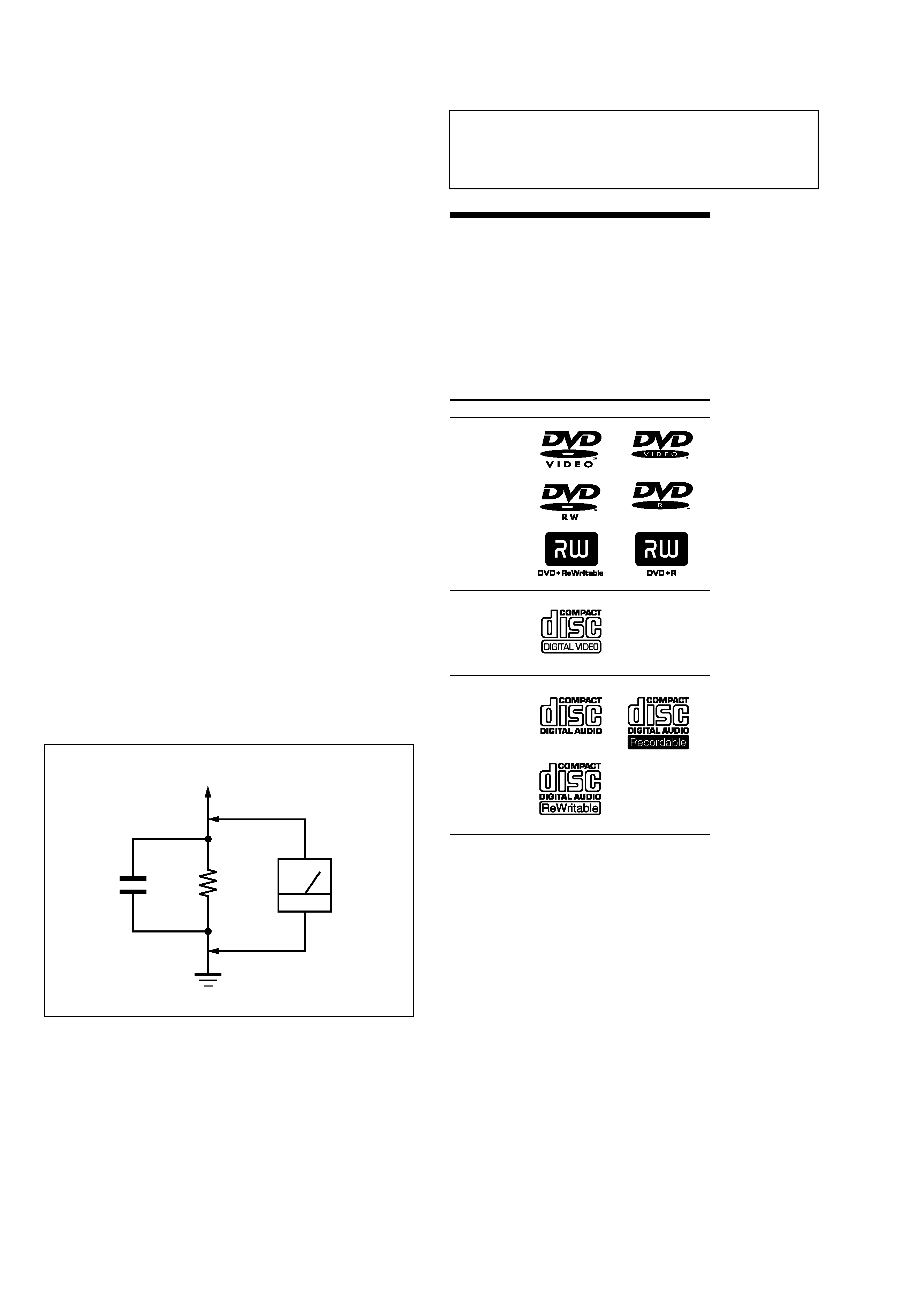
3. Measuring the voltage drop across a resistor by means of a
VOM or battery-operated AC voltmeter. The "limit" indication
is 0.75 V, so analog meters must have an accurate low-voltage
scale. The Simpson 250 and Sanwa SH-63Trd are examples
of a passive VOM that is suitable. Nearly all battery operated
digital multimeters that have a 2 V AC range are suitable. (See
Fig. A)
Fig. A.
Using an AC voltmeter to check AC leakage.
1.5 k
0.15
µF
AC
voltmeter
(0.75 V)
To Exposed Metal
Parts on Set
Earth Ground
About the discs this unit
can play
This unit can play the following discs:
·DVD VIDEO
·DVD-R/DVD+R
·DVD-RW/DVD+RW
·Video CD
·Audio CD
·CD-R/CD-RW
Disc type
Label on the disc
DVD Videos
Video CD
Audio CDs
"DVD VIDEO," "DVD-R" and "DVD-RW" are
trademarks.
Discs that this system cannot play
·CD-ROMs
·CD-Rs/CD-RWs other than those recorded in
the following formats:
-- music CD format
-- video CD format
·Data part of CD-Extras
·Super Audio CDs
·DVD-ROMs
·DVD-RAMs
·DVD Audio discs
·8 cm(3 inches) DVD discs
·Photo Movies created after recording in VR
mode by DVD Handycam.
·Progressive JPEG format file
·Discs with non-standard shapes (e.g., heart,
square, star) cannot be played on this unit.
Attempting to do so may damage the unit.
Do not use such discs.
·A disc with paper or stickers on it
·A disc that has the adhesive, cellophane tape,
or a sticker still left on it.
* A logical format of files and folders on a CD-
ROMs, defined by ISO (International
Organization for standardization).
3
ICF-DVD57TV
Notes about CD-R/CD-RW/DVD-R/
DVD-RW/DVD+R/DVD+RW
·In some cases, CD-Rs, CD-RWs, DVD-Rs,
DVD-RWs, DVD+Rs or DVD+RWs cannot be
played on this system depending upon the
recording quality or physical condition of the
disc, or the characteristics of the recording
device. Furthermore, the disc will not play if
it has not been correctly finalized. For more
information, see the operating instructions
for the recording device.
·A disc recorded in packet write format
cannot be played.
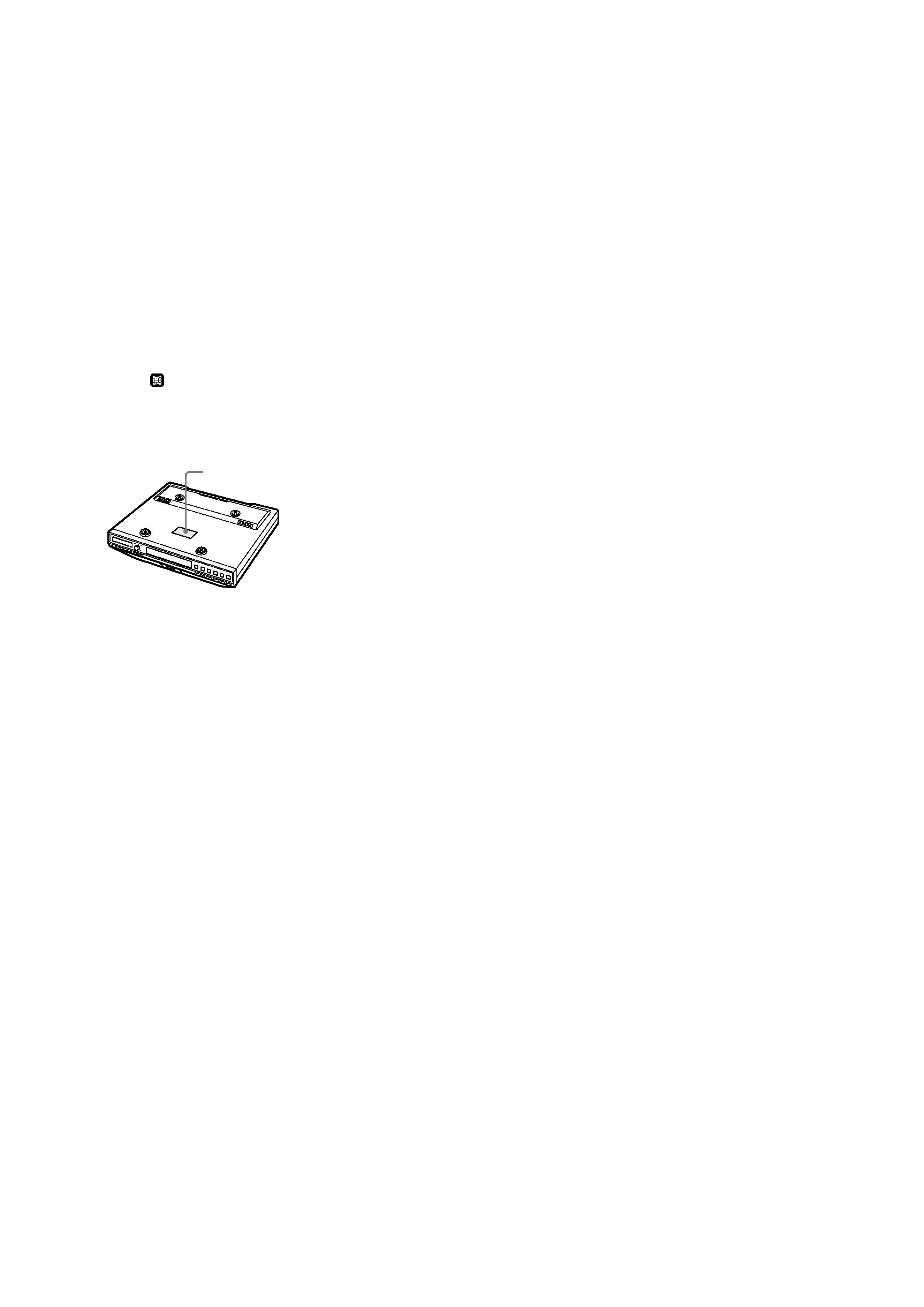
DVD region code this unit can play.
This unit has a region code printed on the top
of the unit and will only play DVDs that are
labeled with identical region codes. DVDs
labeled ALL will also be played on this unit.
If you try to play any other DVD, the message
"WRONG REGION" will appear on the screen.
Depending on the DVD, the region code
indication may not appear even if the DVD is
prohibited by area restrictions.
Note on DTS*-encoded DVDs/CDs
To enjoy DTS Digital SurroundTM playback, an
external 5.1-channel DTS Digital SurroundTM
decoder system must be connected to the
digital output of this unit.
* "DTS," "DTS Digital Surround" and "DTS Digital
Out" are trademarks of Digital Theater Systems,
Inc.
Region code
TABLE OF CONTENTS
1.
SERVICING NOTES ............................................... 4
2.
GENERAL ................................................................... 5
3.
DISASSEMBLY
3-1.
Disassembly Flow ...........................................................
6
3-2.
Cabinet (Upper), Tray Lid Assy ......................................
7
3-3.
Mechanical Deck Assy ....................................................
7
3-4.
Cabinet (Front) Assy .......................................................
8
3-5.
DVD Board ......................................................................
8
3-6.
MAIN Board ....................................................................
9
3-7.
Monitor Assy ...................................................................
9
3-8.
Cabinet (Disp Rear) ......................................................... 10
3-9.
Shield (Disp) .................................................................... 10
3-10. MONITOR Board,
Liquid Crystal Display Panel (LCD1) ............................. 11
3-11. Belt, Tray ......................................................................... 12
3-12. Optical Pick-up KHM-310BAA ...................................... 12
4.
TEST MODE .............................................................. 13
5.
ELECTRICAL ADJUSTMENTS ......................... 16
6.
DIAGRAMS
6-1.
Block Diagram DVD Section .................................... 22
6-2.
Block Diagram TUNER Section ............................... 23
6-3.
Block Diagram AUDIO/PANEL Section .................. 24
6-4.
Block Diagram MONITOR Section .......................... 25
6-5.
Block Diagram POWER SUPPLY Section ............... 26
6-6.
Printed Wiring Board DVD Board (Side A) .............. 28
6-7.
Printed Wiring Board DVD Board (Side B) .............. 29
6-8.
Schematic Diagram DVD Board (1/2) ...................... 30
6-9.
Schematic Diagram DVD Board (2/2) ...................... 31
6-10. Printed Wiring Board TU Board ................................ 32
6-11. Schematic Diagram TU Board .................................. 33
6-12. Printed Wiring Board
MAIN Board (Component Side) ............................... 34
6-13. Printed Wiring Board
MAIN Board (Conductor Side) ................................. 35
6-14. Schematic Diagram MAIN Section (1/4) .................. 36
6-15. Schematic Diagram MAIN Section (2/4) .................. 37
6-16. Schematic Diagram MAIN Section (3/4) .................. 38
6-17. Schematic Diagram MAIN Section (4/4) .................. 39
6-18. Printed Wiring Board LCD Board ............................. 40
6-19. Printed Wiring Boards SWITCH/TRANS Section ...... 41
6-20. Printed Wiring Board
MONITOR Board (Component Side) ....................... 42
6-21. Printed Wiring Board
MONITOR Board (Conductor Side) ......................... 43
6-22. Schematic Diagram MONITOR Board (1/3) ............ 44
6-23. Schematic Diagram MONITOR Board (2/3) ............ 45
6-24. Schematic Diagram MONITOR Board (3/3) ............ 46
7.
EXPLODED VIEWS
7-1.
Cabinet (Upper) Section .................................................. 70
7-2.
Cabinet (Front) Section ................................................... 71
7-3.
Cabinet (Lower) Section-1 .............................................. 72
7-4.
Cabinet (Lower) Section-2 .............................................. 73
7-5.
Monitor Section ............................................................... 74
7-6.
Mechanical Deck Section ................................................ 75
8.
ELECTRICAL PARTS LIST ................................ 76

4
ICF-DVD57TV
SECTION 1
SERVICING NOTES
The laser diode in the optical pick-up block may suffer electro-
static break-down because of the potential difference generated
by the charged electrostatic load, etc. on clothing and the human
body.
During repair, pay attention to electrostatic break-down and also
use the procedure in the printed matter which is included in the
repair parts.
The flexible board is easily damaged and should be handled with
care.
NOTES ON LASER DIODE EMISSION CHECK
The laser beam on this model is concentrated so as to be focused
on the disc reflective surface by the objective lens in the optical
pick-up block. Therefore, when checking the laser diode emis-
sion, observe from more than 30 cm away from the objective lens.
NOTES ON HANDLING THE OPTICAL PICK-UP
BLOCK OR BASE UNIT
UNLEADED SOLDER
Boards requiring use of unleaded solder are printed with the lead-
free mark (LF) indicating the solder contains no lead.
(Caution: Some printed circuit boards may not come printed with
the lead free mark due to their particular size)
: LEAD FREE MARK
Unleaded solder has the following characteristics.
· Unleaded solder melts at a temperature about 40 °C higher than
ordinary solder.
Ordinary soldering irons can be used but the iron tip has to be
applied to the solder joint for a slightly longer time.
Soldering irons using a temperature regulator should be set to
about 350
°C.
Caution: The printed pattern (copper foil) may peel away if the
heated tip is applied for too long, so be careful!
· Strong viscosity
Unleaded solder is more viscou-s (sticky, less prone to flow)
than ordinary solder so use caution not to let solder bridges oc-
cur such as on IC pins, etc.
· Usable with ordinary solder
It is best to use only unleaded solder but unleaded solder may
also be added to ordinary solder.
5
ICF-DVD57TV
SECTION 2
GENERAL
This section is extracted from
instruction manual.
1
3
2
4
5
8
7
qs
qd
qf
qg
qh
qj
qk
ql
w;
wa
ws
wd
qa
0
9
6
Refer to the pages listed for details.
1 DISPLAY RELEASE
2 Disc Tray
3 TIMER dial and TIMER indicator, PUSH
START/STOP button
To operate the Cooking Timer.
4 Clock Display Window
5 Receptor for the remote control
6 CLOCK button
To set the clock.
7 MODE/SCREEN SIZE button
To set the screen mode, and to set the FM
mode.
8 TV MENU button
To change the screen settings.
9 ENTER button
0 SOUND button
To set the audio emphasis.
qa VOLUME +/ buttons
qs Speakers (left/right)
qd
Z OPEN/CLOSE button
qf AUX button
To watch the AUDIO/VIDEO INPUT.
Location of controls
qg TV button
To turn on the TV.
qh DVD button
To turn on the player.
qj RADIO ON/BAND button
To turn on the radio.
* There is a tactile dot on the VOLUME + and
u buttons.
To change the band (FM/AM).
qk OFF button
To turn off the AUX/TV/DVD/Radio
unit.
ql
x (Stop) button
w;
u (Play/Pause) button
wa TV CH/PRESET ,
.(Previous)/
+ ,
>(Next) button
To select a TV channel, to tune in a preset
station, to select the item during TV
MENU operation, or to adjust the screen
settings.
ws RADIO TUNE/TIME SET ,
m(Fast
reverse)/+,
M(Fast forward) button
To tune in a desired radio station or to set
the clock.
This can also be used in slow playback mode.
wd Monitor
Remote control
1
4
0
qa
qs
qd
5
2
3
6
qg
wd
wa
7
8
9
wf
wg
qj
ws
qk
ql
w;
qh
qf
Refer to the pages listed for details.
1 SETUP button
Used to perform menu operations.
2 DISP (Display) button
To display the channel number or the time
information of the disc.
3 AUX button
To watch the AUDIO/VIDEO INPUT.
4 Number buttons
5 REPEAT button
To select the repeat mode (DVD/Video
CD/Audio CD).
6
.(Previous)/>(Next) buttons
qf TV button
To turn on the TV.
qg OFF button
To turn off the AUX/TV/DVD/Radio unit.
qh RADIO/BAND button
To turn on the radio.
qj DVD button
To turn on the unit.
qk TV MENU button
To change the screen settings.
ql
u (Play/Pause) button
w;
x (Stop) button
wa AUDIO button
To change the audio output/audio language.
ws ANGLE button
To select the multiple angles of view while
playing a DVD.
wd ENTER button
To enter a setting.
wf TUNE/CH +/ buttons
To select the desired TV channel, to tune in
to the desired station, to select the item
during TV MENU operation or to adjust
the screen settings.
wg SOUND button
To set the audio emphasis.
The corresponding buttons of the
remote control function the same as
those on the unit.
Instructions in this manual describe how to use
the unit by mainly using the remote control.
* There is a tactile dot on the "5", "
u" and
"TUNE/CH+" buttons of the remote control.
7
tSLOW/m(Fast reverse)/TSLOW/M
(Fast forward) buttons
This can also be used in slow playback
mode.
8 TOP MENU button
To display the top menu of a recorded DVD,
or to set the PBC (playback control)
function on or off for the Video CD.
9
O (Return) button
q;
v/V/b/B buttons
qa MENU button
To display the recorded DVD menu.
qs VOL (Volume) +/ buttons
qd MUTING button
To attenuate the volume.
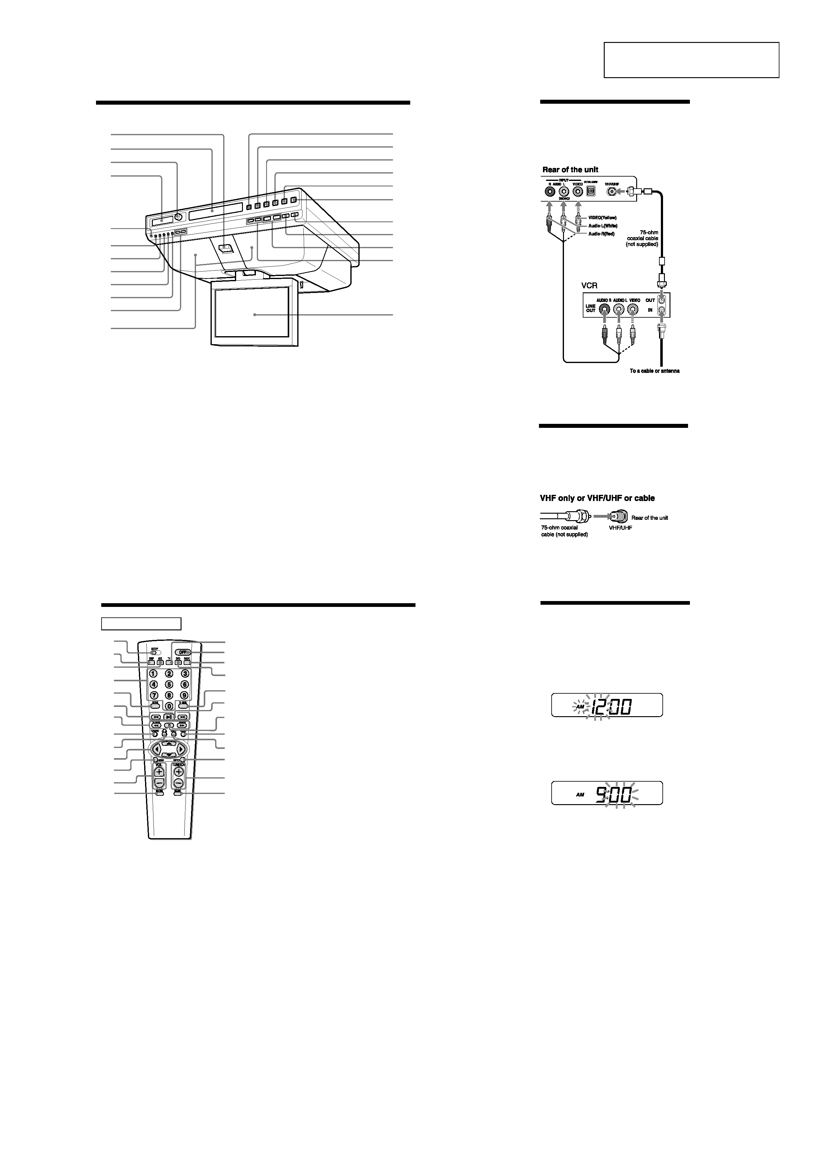
Connection
Use this hookup if you subscribe to a CATV
System that does not require a cable box.
Setting the Clock
1 Plug in the unit.
"AM 12:00" will flash in the Clock Display
Window.
2 Press CLOCK for a few seconds.
You will hear a beep and the hour digits
will start to flash in the Clock Display
Window.
3 Press RADIO TUNE/TIME SET , m(fast
reverse) or +,
M(fast forward) until
the correct hour appears in the Clock
Display Window.
4 Press CLOCK (or ENTER) once.
The minute digits will flash.
5 Press RADIO TUNE/TIME SET , m(fast
reverse) or +,
M(fast forward) until
the correct minute appears in the Clock
Display Window.
6 Press CLOCK (or ENTER) once.
You will hear two short beeps and the
seconds start counting from zero.
Tips
· To set the current time rapidly, hold down
RADIO TUNE/TIME SET ,
m(fast reverse) or +,
M(fast forward).
· To set the current time exactly to the seconds,
adjust the minute function in step 6 and then
press CLOCK (or ENTER) to synchronize it with a
time signal (such as the telephone time signal).
·In the 12-hour system: "AM 12:00" = midnight.
Basic Connections
(Connecting CATV or an
Antenna)
Connecting directly to cable or an antenna