MICROFILM
SERVICE MANUAL
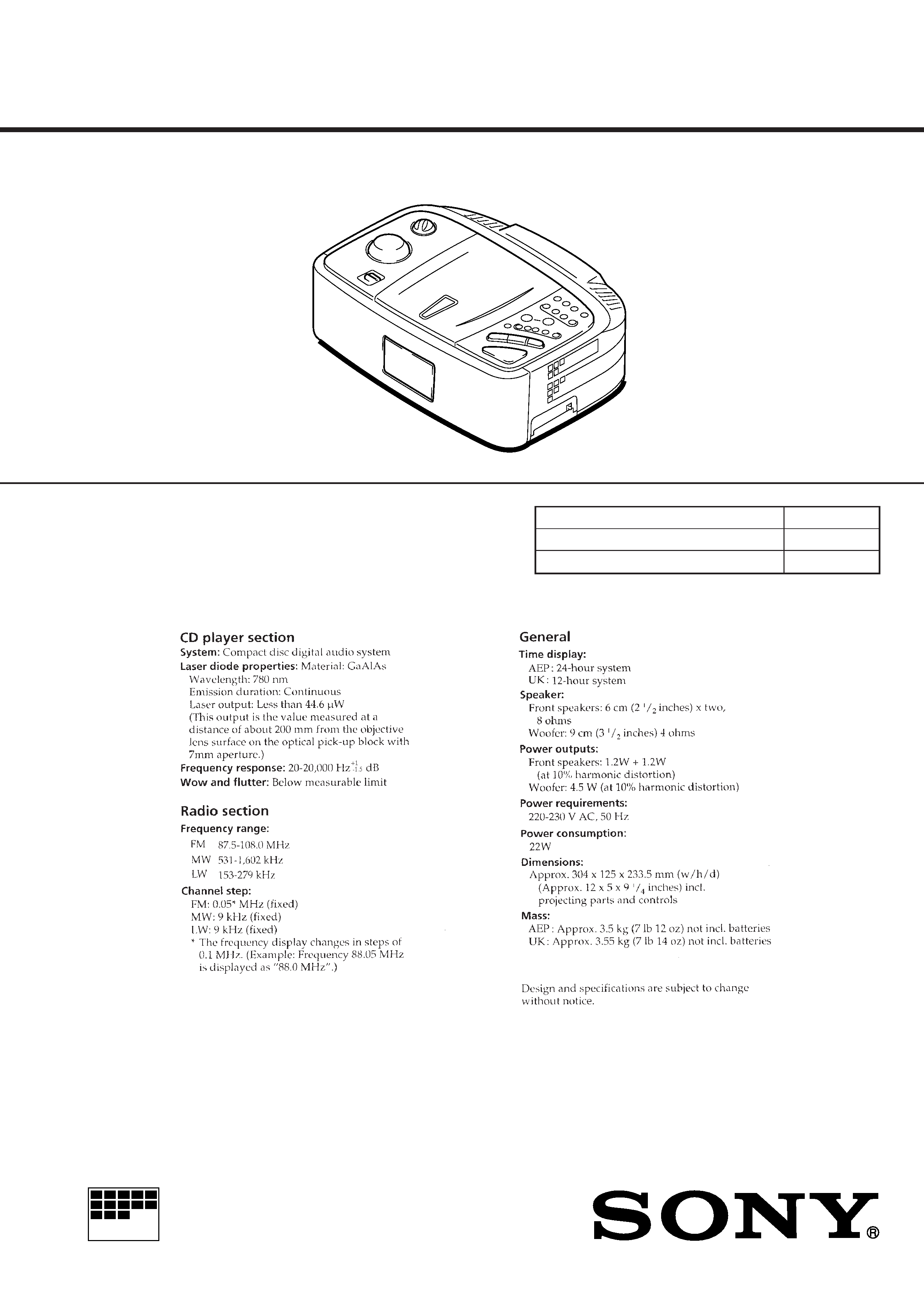
FM/MW/LW CD CLOCK RADIO
AEP Model
UK Model
SPECIFICATIONS
ICF-CD873L
Model Name Using Similar Mechanism
CFD-550
Optical Device Name
KSM-213BAN
Optical Pick-UP Name
KSS-213B
Supplied accessories:
Instruction manual (1)
Ver 1.0 1999. 05
2
TABLE OF CONTENTS
1.
SERVICING NOTES ............................................... 3
2.
GENERAL ................................................................... 4
3.
DISASSEMBLY ......................................................... 5
4.
POWER CORD SETTING ................................... 7
5.
ELECTRICAL ADJUSTMENTS
Tuner Section ..................................................................
8
CD Section ......................................................................
9
Main Clock Section ......................................................... 11
6.
DIAGRAMS
6-1. Block Diagram CD Section ..................................... 13
6-2. Block Diagram TUNER Section ............................. 15
6-3. Block Diagram MAIN Section ................................ 17
6-4. Printed Wiring Boards MAIN Section .................... 22
6-5. Schematic Diagram MAIN Section ......................... 25
6-6. Schematic Diagram POWER SUPPLY Section ...... 30
6-7. Printed Wiring Boards
POWER SUPPLY Section ...................................... 33
6-8. IC Pin Function Description ........................................... 39
7.
EXPLODED VIEWS ................................................ 41
8.
ELECTRICAL PARTS LIST ............................... 45
SAFETY-RELATED COMPONENT WARNING!!
COMPONENTS IDENTIFIED BY MARK
! OR DOTTED
LINE WITH MARK
! ON THE SCHEMATIC DIAGRAMS
AND IN THE PARTS LIST ARE CRITICAL TO SAFE
OPERATION. REPLACE THESE COMPONENTS WITH
SONY PARTS WHOSE PART NUMBERS APPEAR AS
SHOWN IN THIS MANUAL OR IN SUPPLEMENTS PUB-
LISHED BY SONY.
CAUTION
Use of controls or adjustments or performance of procedures
other than those specified herein may result in hazardous ra-
diation exposure.
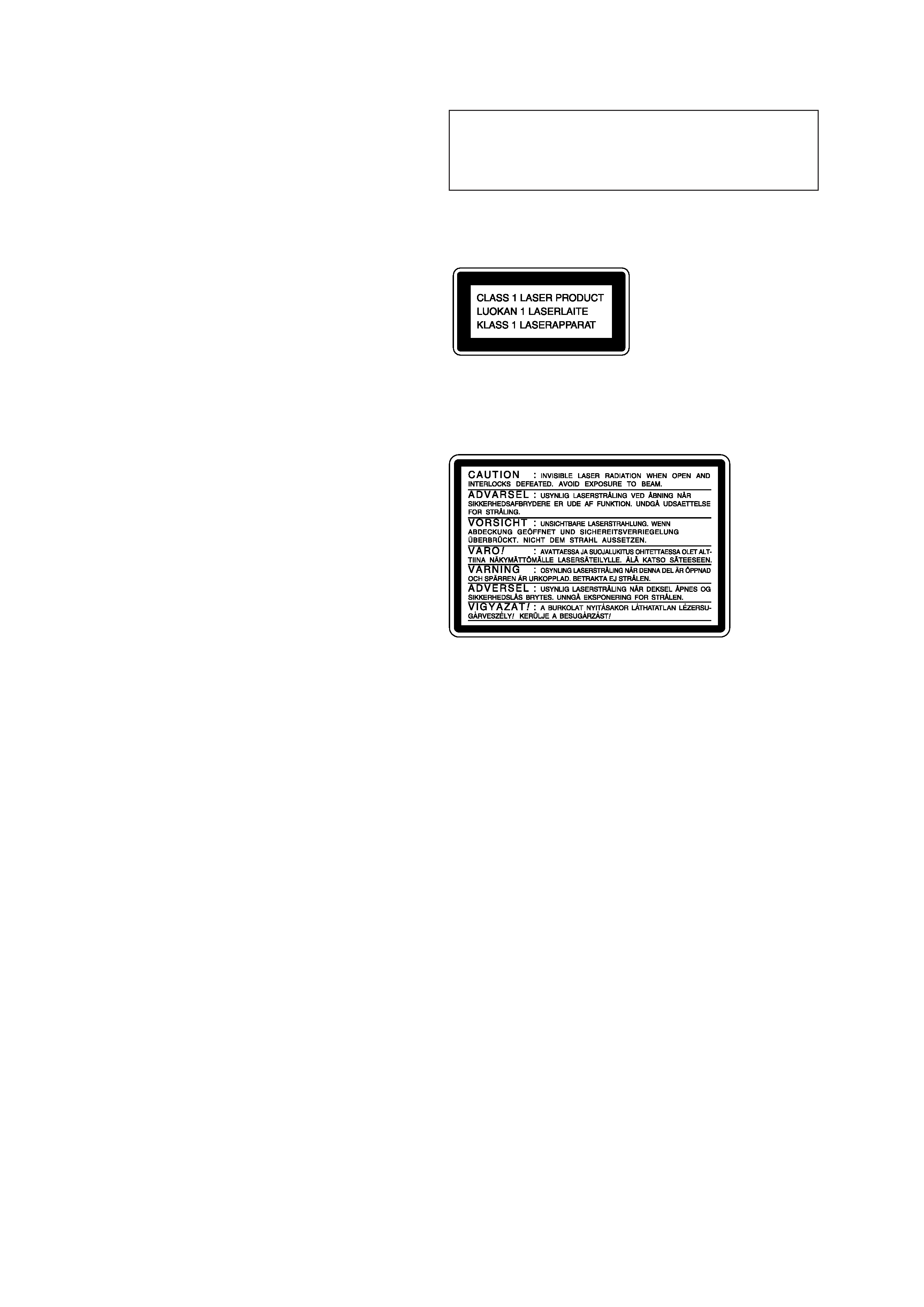
This appliance is classified as a CLASS 1 LASER product.
The CLASS 1 LASER PRODUCT MARKING is located on
the rear exterior.
Laser component in this product is capable of emitting radiation
exceeding the limit for Class 1.
The following caution label is located inside the unit.
3
SECTION 1
SERVICING NOTES
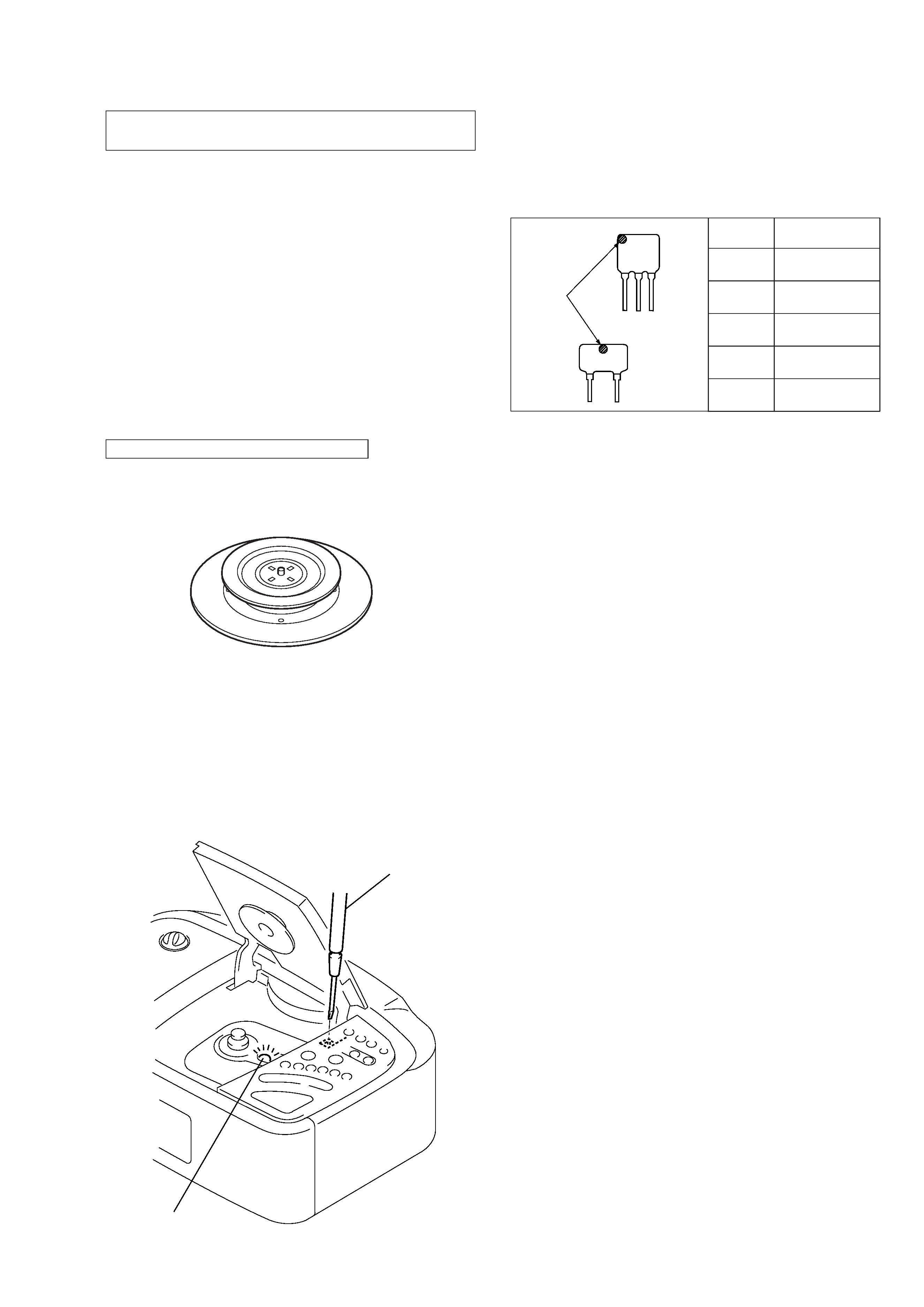
CF2
CF3
mark
Mark
Center frequency
red
10.70 MHz
blue
10.67 MHz
orange
10.73 MHz
black
10.64 MHz
white
10.76 MHz
HOW TO CHANGED THE CERAMIC FILTERS
This model is used two ceramic filters of CF2 and CF3.
You must used same type of color marked ceramic filters in order
to meet same specifications.
Therefore, the ceramic filter must changed two pieces together
since it's supply two pieces in one package as a spare parts.
The laser diode in the optical pick-up block may suffer electro-
static break-down because of the potential difference generated
by the charged electrostatic load, etc. on clothing and the human
body.
During repair, pay attention to electrostatic break-down and also
use the procedure in the printed matter which is included in the
repair parts.
The flexible board is easily damaged and should be handled with
care.
NOTES ON LASER DIODE EMISSION CHECK
The laser beam on this model is concentrated so as to be focused
on the disc reflective surface by the objective lens in the optical
pick-up block. Therefore, when checking the laser diode emis-
sion, observe from more than 30 cm away from the objective lens.
NOTES ON HANDLING THE OPTICAL PICK-UP
BLOCK OR BASE UNIT
Flexible Circuit Board Repairing
· Keep the temperature of the soldering iron around 270 °C dur-
ing repairing.
· Do not touch the soldering iron on the same conductor of the
circuit board (within 3 times).
· Be careful not to apply force on the conductor when soldering
or unsoldering.
Notes on chip component replacement
· Never reuse a disconnected chip component.
· Notice that the minus side of a tantalum capacitor may be dam-
aged by heat.
Insert a precision
screwdriver and
push S424.
laser diode
emission
LASER DIODE AND FOCUS SEARCH OPERATION
CHECK
1. Open the CD lid.
2. Turn on S424 as following figure.
3. Confirm that the laser diode emission while observing the ob-
jecting lens. When there is no emission, Auto Power Control
circuit or Optical Pick-up is broken.
Objective lens moves up and down once for the focus search.
CHUCK PLATE JIG ON REPAIRING
On repairing CD section, playing a disc without the CD lid, use
Chuck Plate Jig.
· Code number of Chuck Plate Jig: X-4918-255-1
4
SECTION 2
GENERAL
This section is extracted from
instruction manual.
5
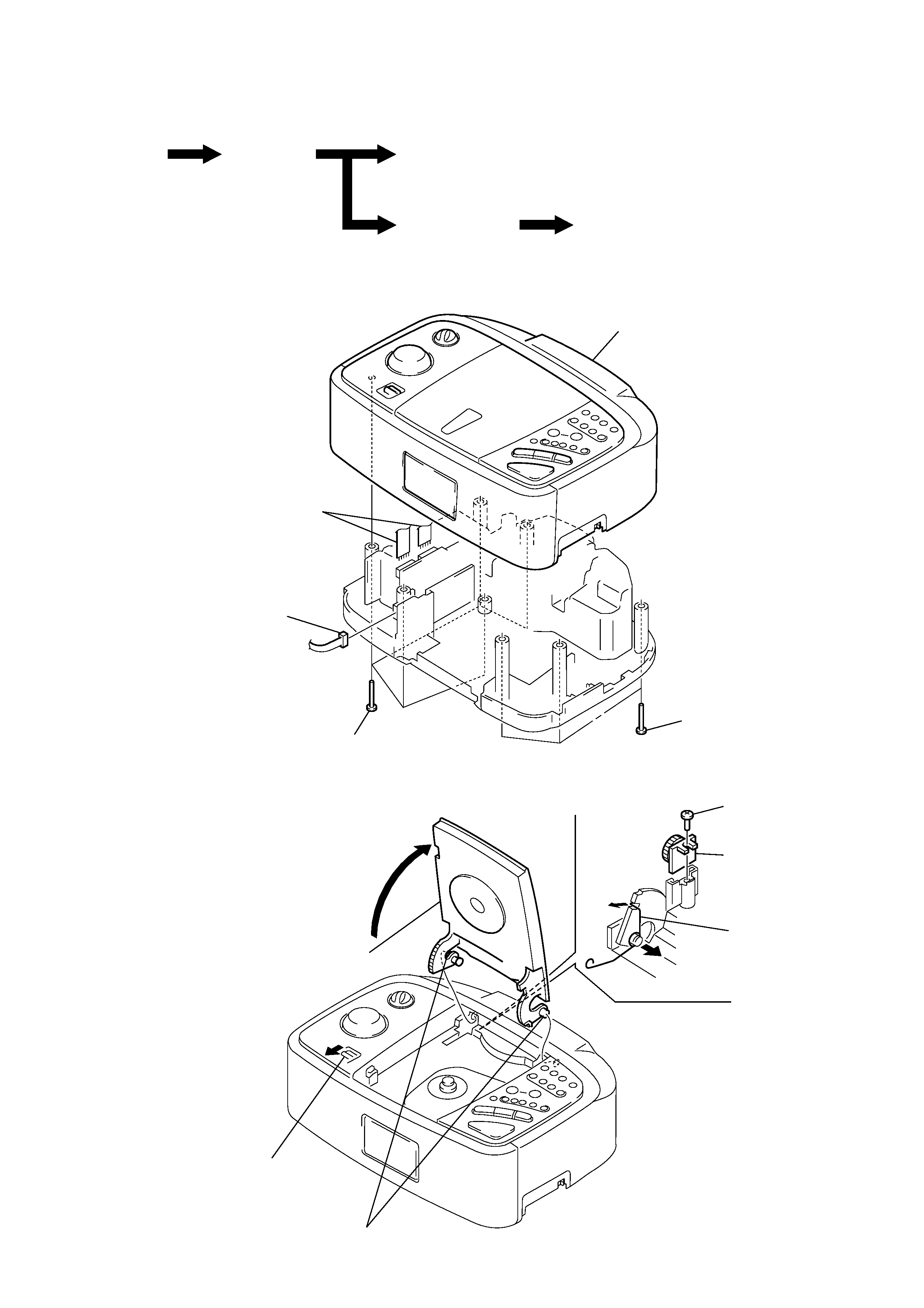
UPPER CABINET SECTION
CD LID ASSY
SECTION 3
DISASSEMBLY
Note: Follow the disassembly procedure in the numerical order given.
· This set can be disassembled in the order shown below.
Set
Upper cabinet
section
CD lid assy
Main board section
Optical pick-up section
1 five screws
(P3
× 14)
2 upper cabinet section
3 two flat wires
(CN303, 304)
4 connector
(CN306)
1 three screws
(P3
× 14)
1 Pull the button (open).
6 two bosses
2 Open the CD lid assy.
7 Remove the CD lid
assy.
3 screw
(B3
× 10)
4 damper
5 spring
(CD open)