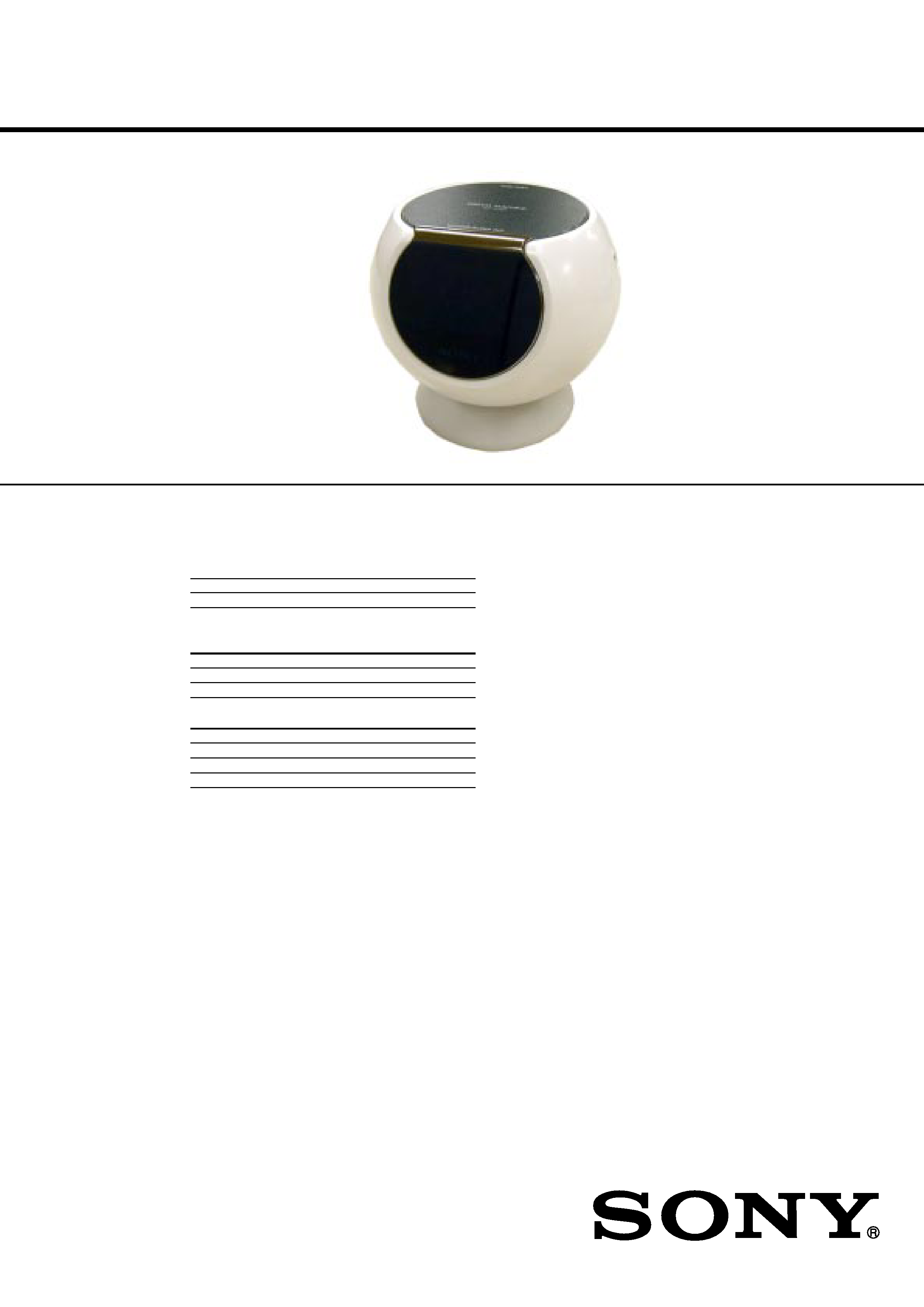
ICF-C763/C763L
SERVICE MANUAL
ICF-763
FM/AM PLL SYNTHESIZED CLOCK RADIO
ICF-763L
FM/MW/LM PLL SYNTHESIZED CLOCK RADIO
SPECIFICATIONS
US Model
Canadian Model
ICF-C763
AEP Model
ICF-C763/C763L
UK Model
ICF-C763L
Ver 1.0 2004.05
9-877-783-01
2004E02-1
© 2004.05
Sony Corporation
Personal Audio Company
Published by Sony Engineering Corporation
Time display
UK, North and South America
12-hour system
Other countries/regions
24-hour system
Frequency range
Model for North and South America
Band
ICF-C763
Channel step
FM
87.5 - 108 MHz
0.1 MHz
AM
530 - 1 710 kHz
10 kHz
Model for other countries/Regions
Band
ICF-C763
ICF-C763L
Channel step
FM
87.5 - 108 MHz 87.5 - 108 MHz 0.05 MHz
AM (MW) 531 - 1 602 kHz 531 - 1 602 kHz 9 kHz
LW
--
153 - 279 kHz
3 kHz
Speaker
Approx. 5.7 cm (2 1/
4 inches) dia. 4
Power output
200 mW (at 10 % harmonic distortion)
Power requirements
North and South American model
: 120 V AC, 60 Hz
Other model
: 230 V AC, 50 Hz
Dimensions
Approx. 115.5 x 105 x 110.6 mm (w/h/d) (4 5/
8 x 4
1/
4 x 4
3/
8 inches)
including projecting parts and controls
Mass
Approx. 665 g (1 lb 7.5 oz)
Approx. 675 g (1 lb 7.8 oz): ICF-C763L (UK model)
Approx. 600 g (1 lb 5.2 oz): ICF-C763 (North and South America model)
Design and specifications are subject to change without notice.
ICF-C763/C763L
2
TABLE OF CONTENTS
Specifications ........................................................................... 1
1. GENERAL
Location and Function of Controls .................................... 3
2. ELECTRICAL ADJUSTMENTS ............................. 4
3. DIAGRAMS
3-1.IC Block Diagrams ...................................................... 6
3-2. IC Pin Function Descriptions ..................................... 7
3-3. Printed Wiring Board Main section ...................... 8
3-4. Schematic Diagram Main section .......................... 9
3-5. Printed Wiring Board Contrd section ................. 10
3-6. Schematic Diagram Contrd section ................... 11
3-7. Printed Wiring Board Power section .................. 12
3-8. Schematic Diagram Power section ..................... 12
4. EXPLODED VIEW
4-1.Cabinet (Upper) Section ............................................ 13
5. ELECTRICAL PARTS LIST ................................... 14
SAFETY-RELATED COMPONENT WARNING!!
COMPONENTS IDENTIFIED BY MARK 0 OR DOTTED LINE WITH
MARK 0 ON THE SCHEMATIC DIAGRAMS AND IN THE PARTS
LIST ARE CRITICAL TO SAFE OPERATION.
REPLACE THESE COMPONENTS WITH SONY PARTS WHOSE
PART NUMBERS APPEAR AS SHOWN IN THIS MANUAL OR IN
SUPPLEMENTS PUBLISHED BY SONY.
· HOW TO CHANGE THE CERAMIC FILTER
This model is used two ceramic filters of CF2 and CF3.
You must use same type of color marked ceramic filters in
order to meet same specifications.
Therefore, the ceramic filter must change two pieces together
since it's supply two pieces in package as a spare parts.
SAFETY CHECK-OUT
After correcting the original service problem, perform the following
safety checks before releasing the set to the customer:
Check the antenna terminals, metal trim, "metallized" knobs, screws,
and all other exposed metal parts for AC leakage. Check leakage as
described below.
LEAKAGE
The AC leakage from any exposed metal part to earth Ground and
from all exposed metal parts to any exposed metal part having a
return to chassis, must not exceed 0.5 mA (500 microampers).
Leakage current can be measured by any one of three methods.
1. A commercial leakage tester, such as the Simpson 229 or RCA
WT-540A. Follow the manufacturers' instructions to use these
instruments.
2. A battery-operated AC milliammeter. The Data Precision 245
digital multimeter is suitable for this job.
3. Measuring the voltage drop across a resistor by means of a
VOM or battery-operated AC voltmeter. The "limit" indication
is 0.75 V, so analog meters must have an accurate low-voltage
scale. The Simpson 250 and Sanwa SH-63Trd are examples
of a passive VOM that is suitable. Nearly all battery operated
digital multimeters that have a 2V AC range are suitable. (See
Fig. A)
Fig. A. Using an AC voltmeter to check AC leakage.
ATTENTION AU COMPOSANT AYANT RAPPORT
À LA SÉCURITÉ!!
LES COMPOSANTS IDENTIFIÉS PAR UNE MARQUE 0 SUR LES
DIAGRAMMES SCHÉMATIQUES ET LA LISTE DES PIÈCES
SONT CRITIQUES POUR LA SÉCURITÉ DE FONCTIONNEMENT.
NE REMPLACER CES COMPOSANTS QUE PAR DES PIÈCES
SONY DONT LES NUMÉROS SONT DONNÉS DANS CE MANUEL
OU DANS LES SUPPLÉMENTS PUBLIÉS PAR SONY.
0.15
µF
To Exposed Metal
Parts on Set
1.5k
AC
voltmeter
(0.75V)
Earth Ground
mark
mark
CF3
CF2
no mark
blue
orange
black
white
10.70MHz
10.67MHz
10.73MHz
10.64MHz
10.76MHz
Mark
Center
frequency
ICF-C763/C763L
3
SECTION 1
GENERAL
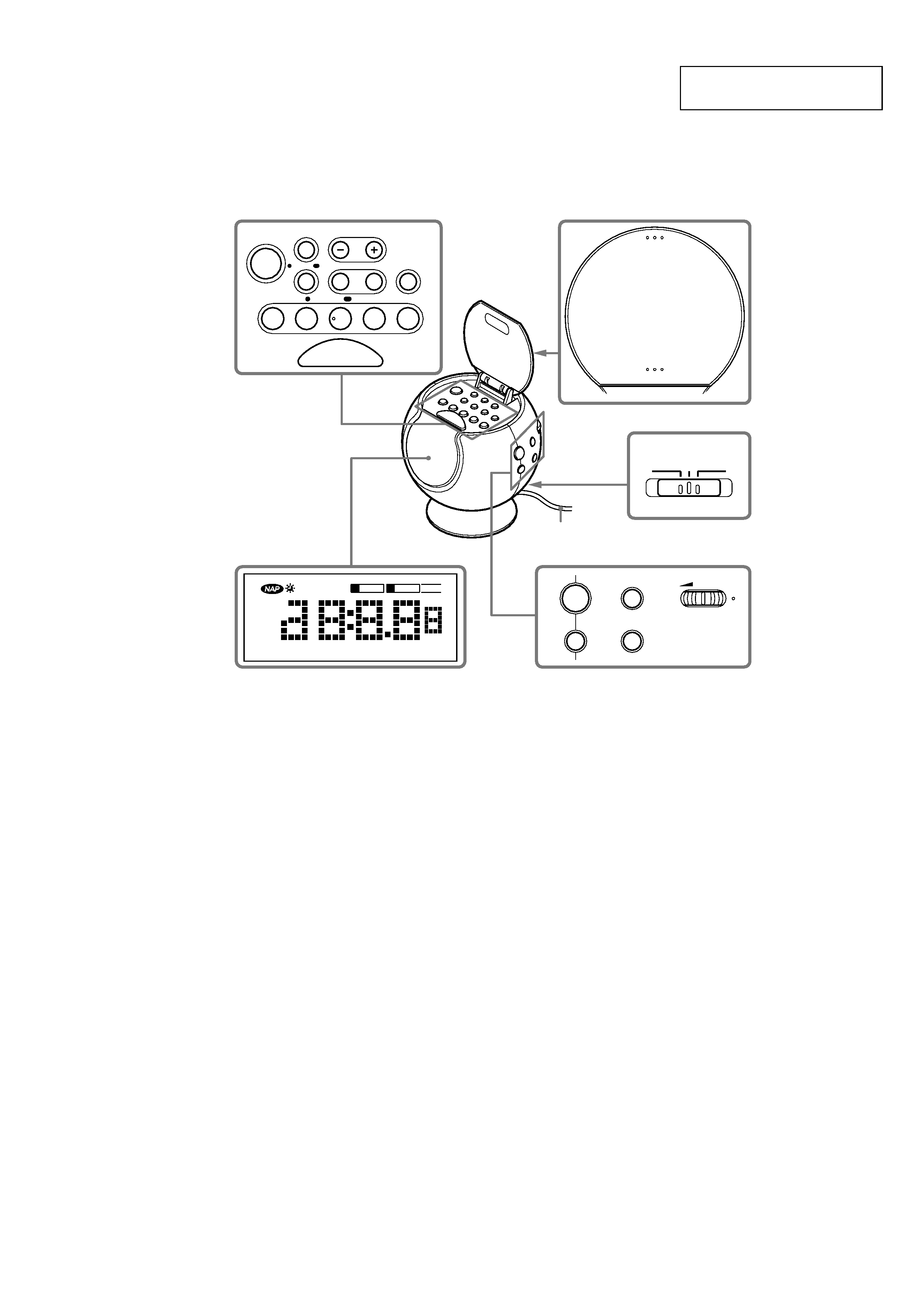
LOCATION AND FUNCTION OF CONTROLS
This section is extracted from
instruction manual.
OFF
ON
NIGHT LIGHT MODE
STANDBY
A RADIO
SLEEP
FM12
MW
AM
LW
PM
MHz kHz
RADIO
B SOUND 12345
WAKE UP
PRESET
PRESET
OFF
RADIO
ON
BAND
SLEEP
VOLUME
BRIGHTNESS
TUNE/TIME SET
CLOCK
D.S.T./
ALARM MODE
ALARM
AB
5
4
3
2
1
NAP
ENTER
SELECT
PRESET
SNOOZE/
SLEEP OFF
PUSH OPEN
SNOOZE/SLEEP OFF
AC power cord
The PRESET 3 button and VOLUME have a tactile dot.
ICF-C763/C763L
4
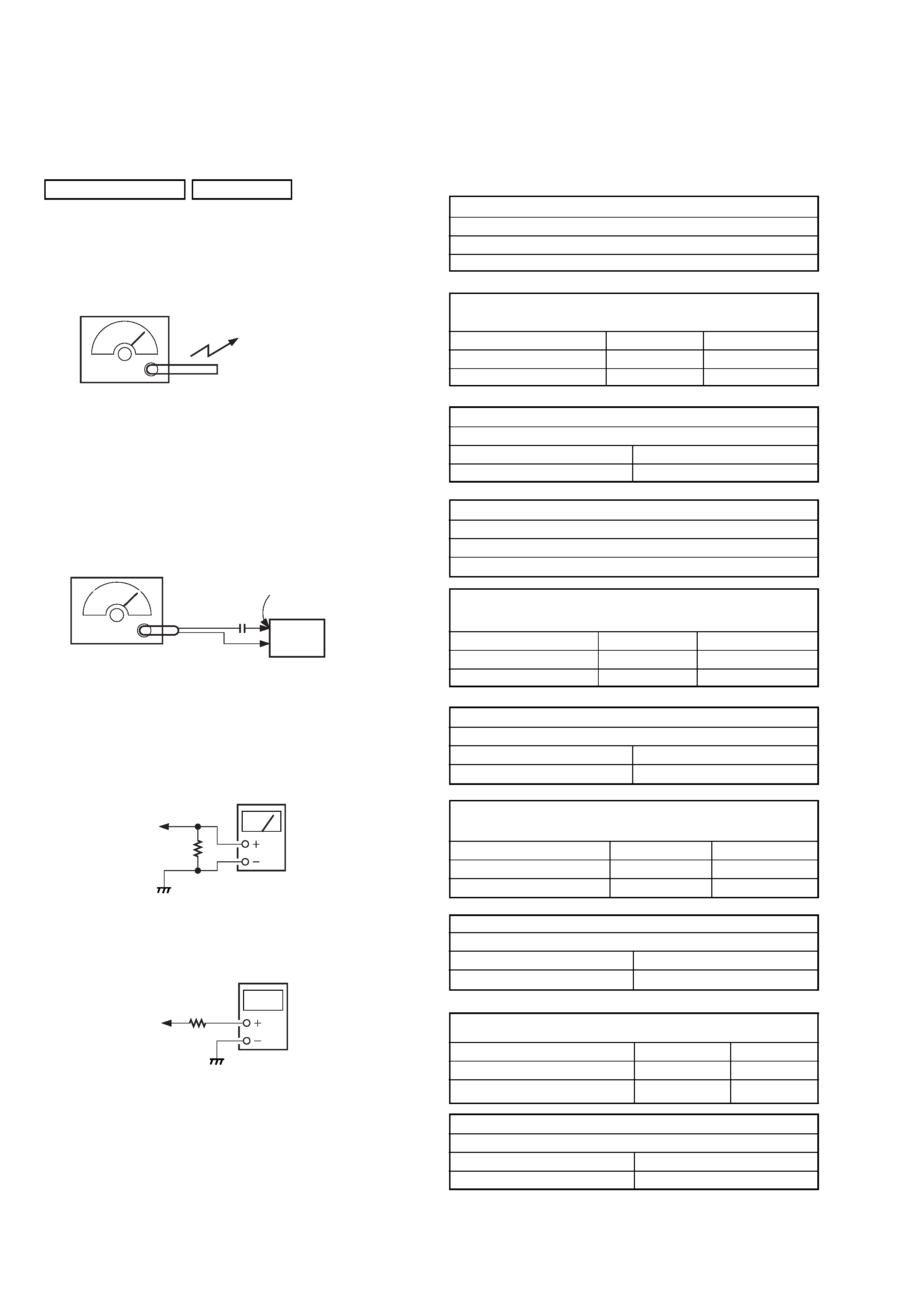
AM IF ADJUSTMENT
Adjust for a maximum reading on level meter.
T1
450 kHz
AM FREQUENCY COVERAGE
ADJUSTMENT
Frequency Display
530 kHz [531 kHz] 1,710 kHz [1,602 kHz]
Reading on Digital voltmeter
3.0
± 0.1 V
10.0
± 1.0V[9.0 ± 1.0V]
Adjustment Part
L4
<confirmation>
AM TRACKING ADJUSTMENT
Adjust for a maximum reading on level meter.
L1
CT1
530 kHz [531kHz]
1.490 kHz [1.404kHz]
MW IF ADJUSTMENT
Adjust for a maximum reading on level meter.
T1
450 kHz
MW FREQUENCY COVERAGE
ADJUSTMENT
Frequency Display
531 kHz
1.602 kHz
Reading on Digital voltmeter
2.75
± 0.1 V
9.0
± 1.0 V
Adjustment Part
L4
<confirmation>
MW TRACKING ADJUSTMENT
Adjust for a maximum reading on level meter.
L1
CT1
621 kHz
1.404 kHz
LW FREQUENCY COVERAGE
ADJUSTMENT
Frequency Display
153 kHz
279 kHz
Reading on Digital voltmeter
2.3
± 0.3 V
9.0
± 0.1 V
Adjustment Part
<confirmation>
CT4
LW TRACKING ADJUSTMENT
Adjust for a maximum reading on level meter.
L1
CT2
162 kHz
243 kHz
· ICF-C763/C763L
FM FREQUENCY COVERAGE
CONFIRMATION
Frequency Display
87.5 MHz
108 MHz
Reading on Digital voltmeter
3.2
± 0.3 V
10.0
± 1.5 V
Adjustment Part
<confirmation>
<confirmation>
FM TRACKING ADJUSTMENT
Adjust for a maximum reading on level meter.
L2
CT3
87.5 MHz
108 MHz
SECTION 2
ELECTRICAL ADJUSTMENTS
< > : ICF-C763L
TUNER SECTION
0 dB = 1
µV
· FM Section
Setting:
BAND button:FM
Put the lead-wire
antenna close to
the set.
AM RF signal
generator
30% amplitude
modulation by
400 Hz signal
· AM Section
Setting:
BAND button: AM <MW and LW>
TP (ANT)
FM RF signal
generator
0.01
µF
set
22.5 kHz frequency
deviation by 400 Hz signal
output level : as low as possible
· Connecting Level Meter (FM, AM<MW and LW>)
32
SPK+
level meter
(range 0.5-5V AC)
digital
voltmeter
100 k
TP (VT)
· Connecting Digital Voltmeter (FM, AM <MW and LW>)
· Repeat the procedures in each adjustment several times, and the
frequency coverage and tracking adjustments should be finally
done by the trimmer capacitors.
Adjustment and Connect Location: See page 5.
· ICF-C763
[ ] : Italian model
· ICF-C763L
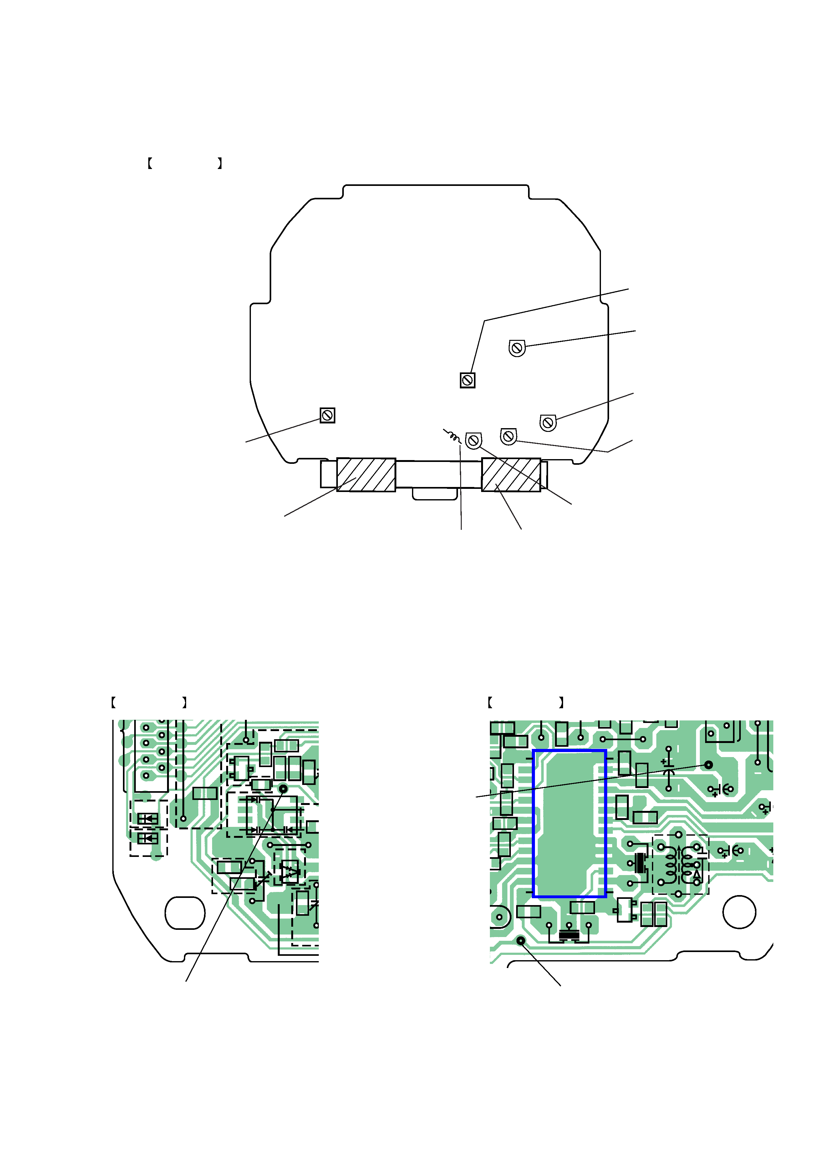
ICF-C763/C763L
5
L2 : FM tracking
adjustment
CT2 : LW
tracking
adjustment
L1 : AM (MW)
tracking
adjustment
CT1 : AM (MW)
tracking
adjustment
MAIN BOARD
(Component Side)
L4 : AM (MW)
Frequency coverage
adjustment
CT4 : LW
Frequency coverage
adjustment
CT3 : FM tracking
adjustment
L1 : LW tracking
adjustment
T1 : AM (MW)
IF adjustment
JC1
C14
C44
C20
R8
R9
R6
C4
JW1
JW12
C22
C2
C8
C9
C30
C11
C10
JC1
C26
C28
C15
E
E
B
E
B
C
E
B
C
C
B
C
B
E
C
B
E
JC
C
R
JW4
R22
R14
C23
R15
C24
C29
L3
C33
C36
C34
C32
R3
C12
C13
JW9
R7
CT4
CT1
CT2
CT3
C43
D103
D104
C7:C763
JC7:C763L
C763
C763L
C763L
C763L
C6
JW8
C5
R5
C1
R2
R4
C3
D2
R18
R20
C40
R17
R16
C37
T1
CF1
C31
SPK+
C3
C39
R13
C27
R21
JC2
D3
L2
L4
BPF1
CF2
C25
US,CND
IT
,UK
IT,AEP
JW110
JW3
R19
C41
R1
Q1
D4
Q4
Q6
Q7
Q2
D1
IC1
1 2
1
2
1
14
15
28
TP(ANT)
TP(VT)
MAIN BOARD
(Conductor Side)
MAIN BOARD
(Conductor Side)
TP (VT)
TP (ANT)
SPK+
Adjustment and Connect Location