1
SERVICE MANUAL
Singapore Model
ICF-C411
FM/AM CLOCK RADIO
SPECIFICATIONS
Ver 1.0 2001.03
Sony Corporation
Audio Entertainment Group
General Engineering Dept.
9-873-096-11
2001C0400-1
© 2001.3
Time display
24-hour system
Frequency range
FM: 87.5 - 108 MHz
AM: 530 - 1710 kHz
Speaker
Approx. 6.6 cm (2 5/8 inches) dia., 8 ohm
Power output
120 mW (at 10% harmonic distortion)
Power requirements
220 - 230 V AC, 50 Hz
For the power back-up function: 9 V DC, one 6F22 battery
Battery life
Approx. 20 hours (for clock backup), using Sony S-006P
(6F22) battery
Dimensions
Approx. 215
× 106.4 × 99.8 mm (w/h/d)
(8 1/2
× 4 1/4 × 4 inches) incl. projecting parts and controls
Mass
Approx. 780 g (1 lb 11.5 oz) not incl. battery
Design and specifications are subject to change without notice.

2
SAFETY-RELATED COMPONENT WARNING!!
COMPONENTS IDENTIFIED BY MARK 0 OR DOTTED LINE
WITH MARK 0 ON THE SCHEMATIC DIAGRAMS AND IN
THE PARTS LIST ARE CRITICAL TO SAFE OPERATION.
REPLACE THESE COMPONENTS WITH SONY PARTS WHOSE
PART NUMBERS APPEAR AS SHOWN IN THIS MANUAL OR
IN SUPPLEMENTS PUBLISHED BY SONY.
Notes on Chip Component Replacement
· Never reuse a disconnected chip component.
· Notice that the minus side of a tantalum capacitor may be dam-
aged by heat.
ICF-C411
TABLE OF CONTENTS
1. SERVICING NOTES
1-1. Cord Dressing (Power Cord) ............................................... 3
1-2. Pointer Alignment ............................................................... 3
2. GENERAL ............................................................................ 4
3. DISASSEMBLY
3-1. Cabinet (Upper) Section ...................................................... 5
3-2. Main Board ......................................................................... 6
3-3. Key Board, LED Board ....................................................... 6
4. ELECTRICAL ADJUSTMENTS ................................... 7
5. DIAGRAMS
5-1. Circuit Boards Location ...................................................... 9
5-2. Block Diagram .................................................................. 10
5-3. Printed Wiring Boards Main, Power Section .............. 11
5-4. Printed Wiring Boards Key, LED Section ................... 12
5-5. Schematic Diagram ........................................................... 13
6. EXPLODED VIEWS
6-1. Cabinet (Upper) Section .................................................... 14
6-2. Chassis Section ................................................................. 15
6-3. Cabinet (Lower) Section ................................................... 16
7. ELECTRICAL PARTS LIST ......................................... 17
3
ICF-C411
SECTION 1
SERVICING NOTES
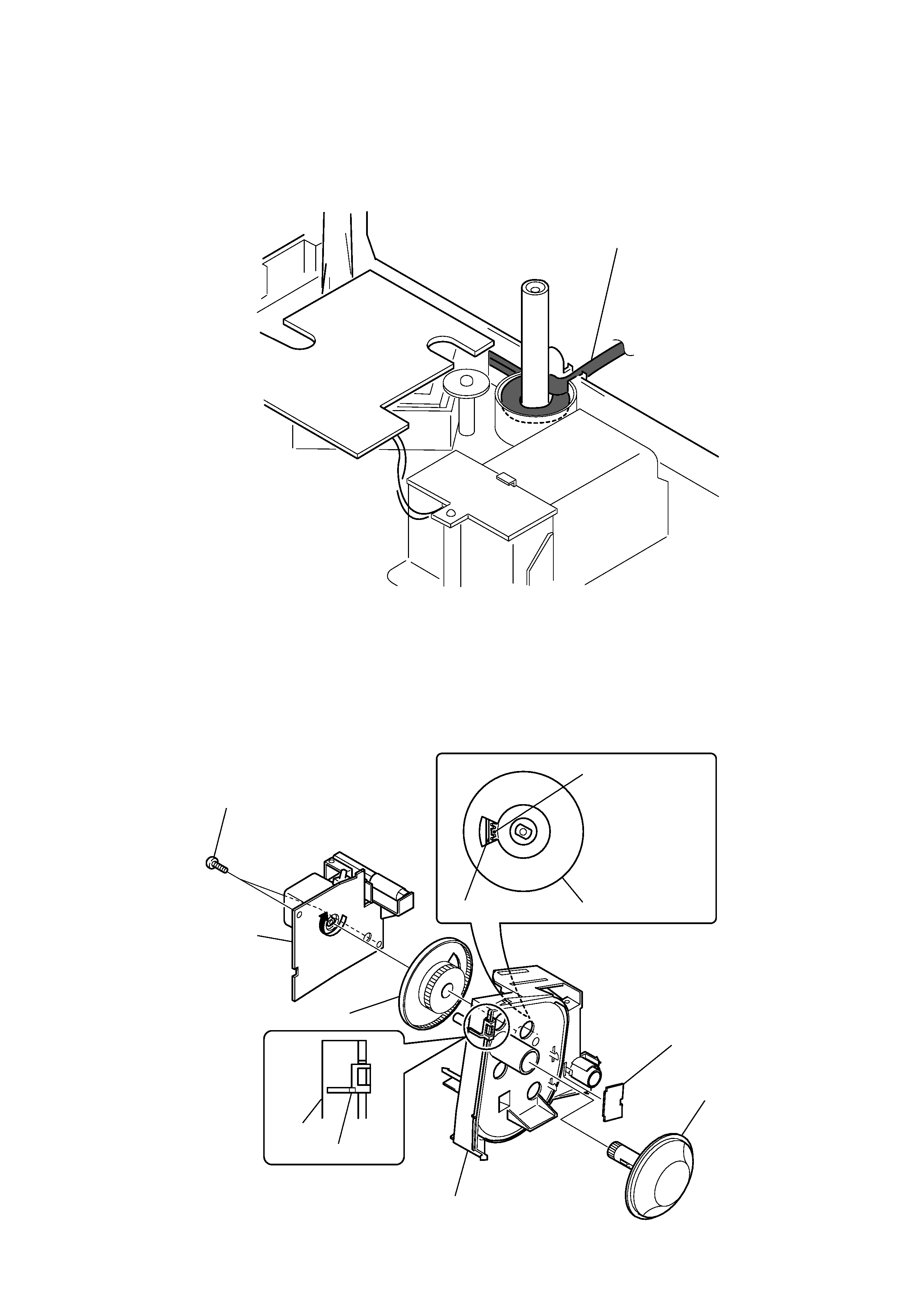
1-2. POINTER ALIGNMENT
power cord
7
screws (P 3x10)
2
pointer retainer board
8
knob (tuning)
4
gear (VC)
6
MAIN board
gear (VC)
Align is the projection.
1
5
3
chassis
chassis
pointer
pointer
1-1. CORD DRESSING
(POWER CORD)
1) Set the power cord as shown in the figure.
4
ICF-C411
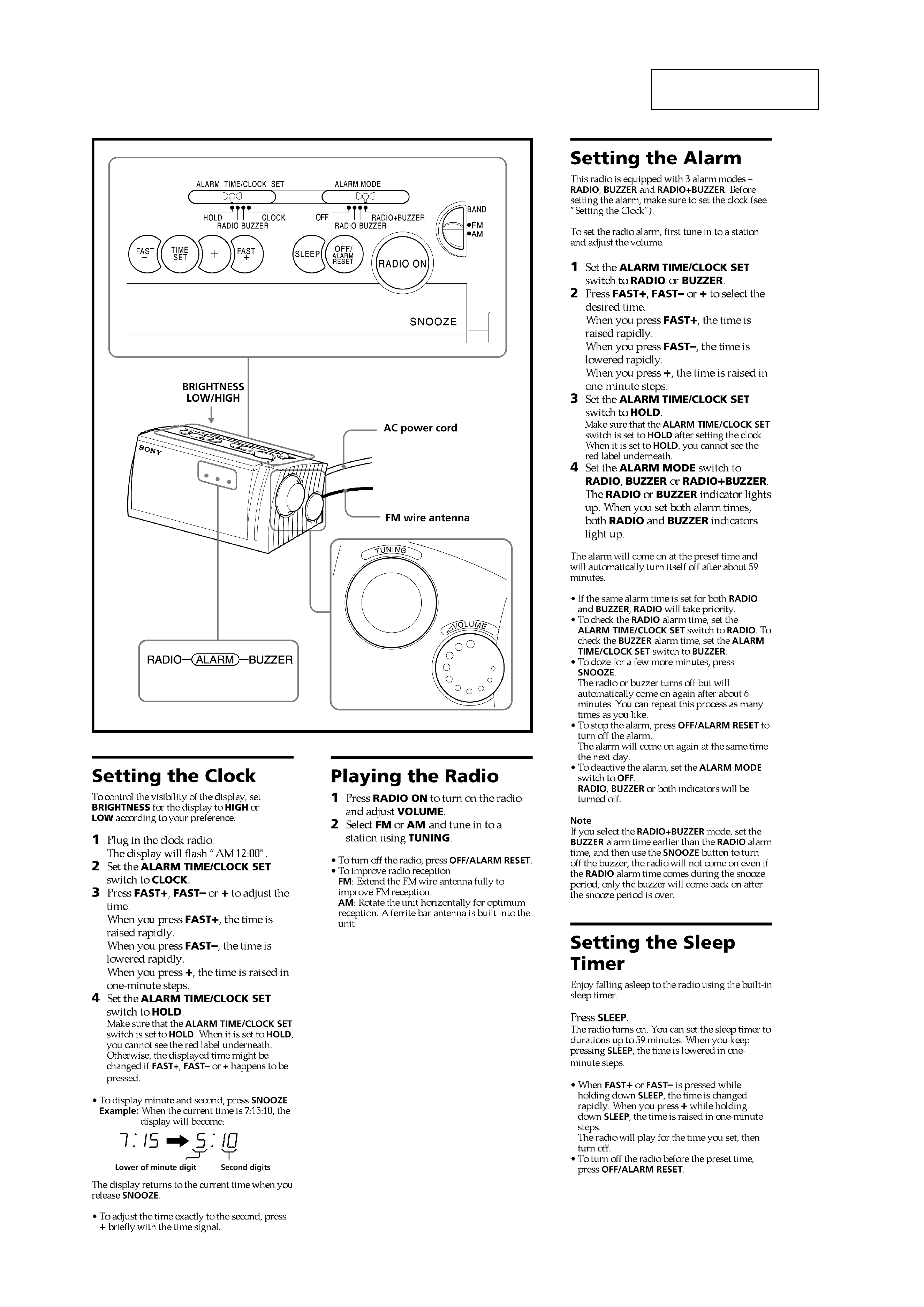
SECTION 2
GENERAL
This section is extracted
from instruction manual.
5
ICF-C411
· The equipment can be removed using the following procedure.
SECTION 3
DISASSEMBLY
Note : Follow the disassembly procedure in the numerical order given.
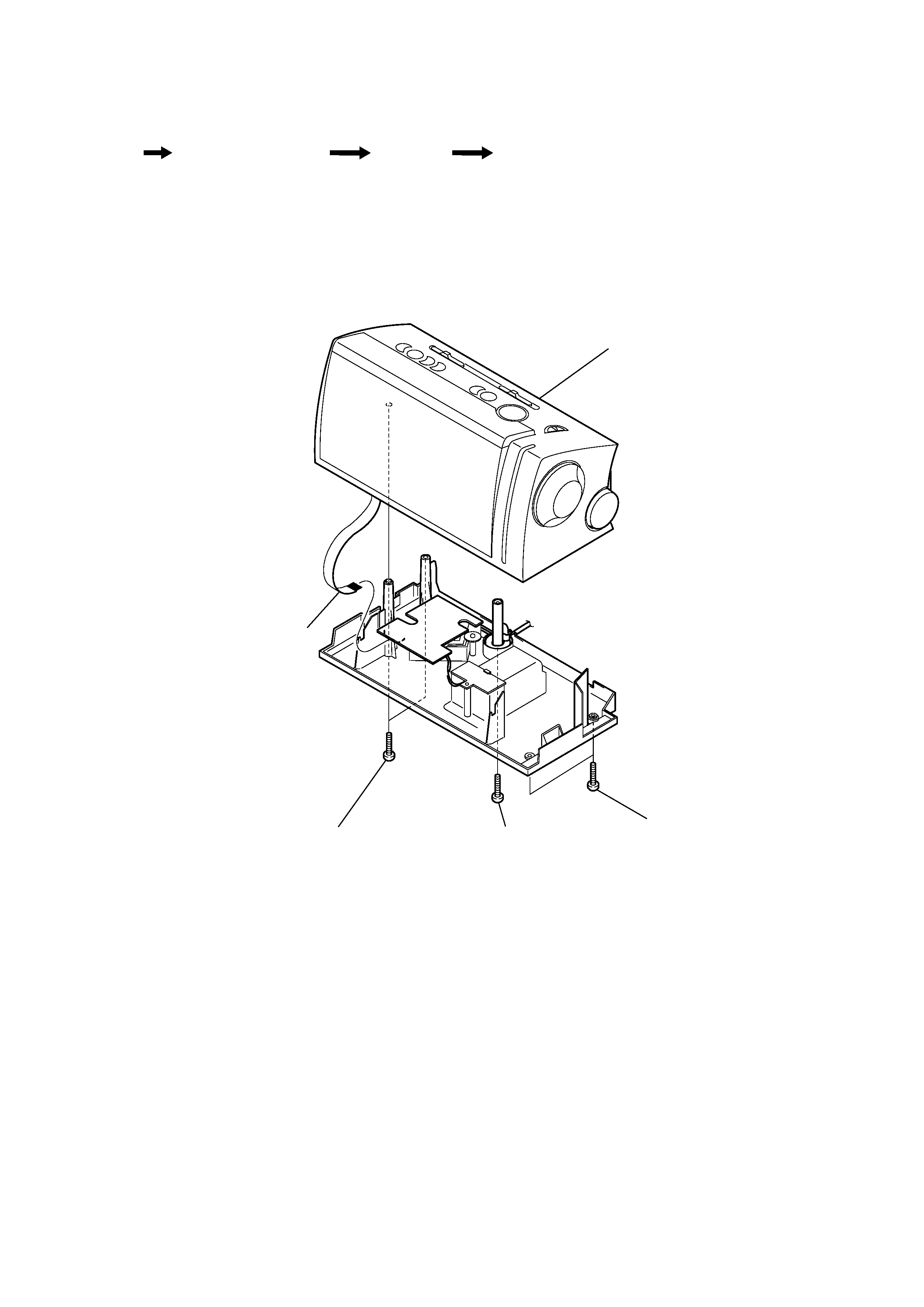
3-1. CABINET (UPPER) SECTION
Set
Cabinet (Upper) Section
Main Board
Key Board, LED Board
1
screws (P 3x14)
5
cabinet (upper) section
4
CN301
2
screws (P 3x14)
3
screw (P 3x14)