
1
ICF-B200
SERVICE MANUAL
US Model
Canadian Model
AEP Model
Ver 1.0 2001. 01
FM/AM RADIO
Ver 1.3 2001. 02
Sony Corporation
Audio Entertainment Group
General Engineering Dept.
9-925-744-13
2001B0400-1
© 2001. 2
Frequency range
FM : 87.5 108 MHz
AM : 530 1,605 kHz
Speaker
Approx. 4.5 cm (1 3/4 inches) dia., 8 ohms
Power output
60 mW (Using the built-in rechargeable
battery)
90 mW (Using size AA (R6) dry batteries, not
supplied)
Output
v
jack (minijack)
Power requirements
Built-in nickel-cadmium (2.4 V, 300 mAh,
Ni-Cd) battery or 3 V DC, two size AA (R6) dry
batteries
Dimensions
Approx. 163
× 80 × 55 mm (w/h/d)
(6 1/2
× 3 1/4 × 2 1/4 in)
Mass
Approx. 320 g (11.3 oz)
Approx. 355 g (12.6 oz) incl. batteries and
projecting parts
Supplied accessory
Hand strap (1)
Design and specifications are subject to change
without notice.
SPECIFICATIONS
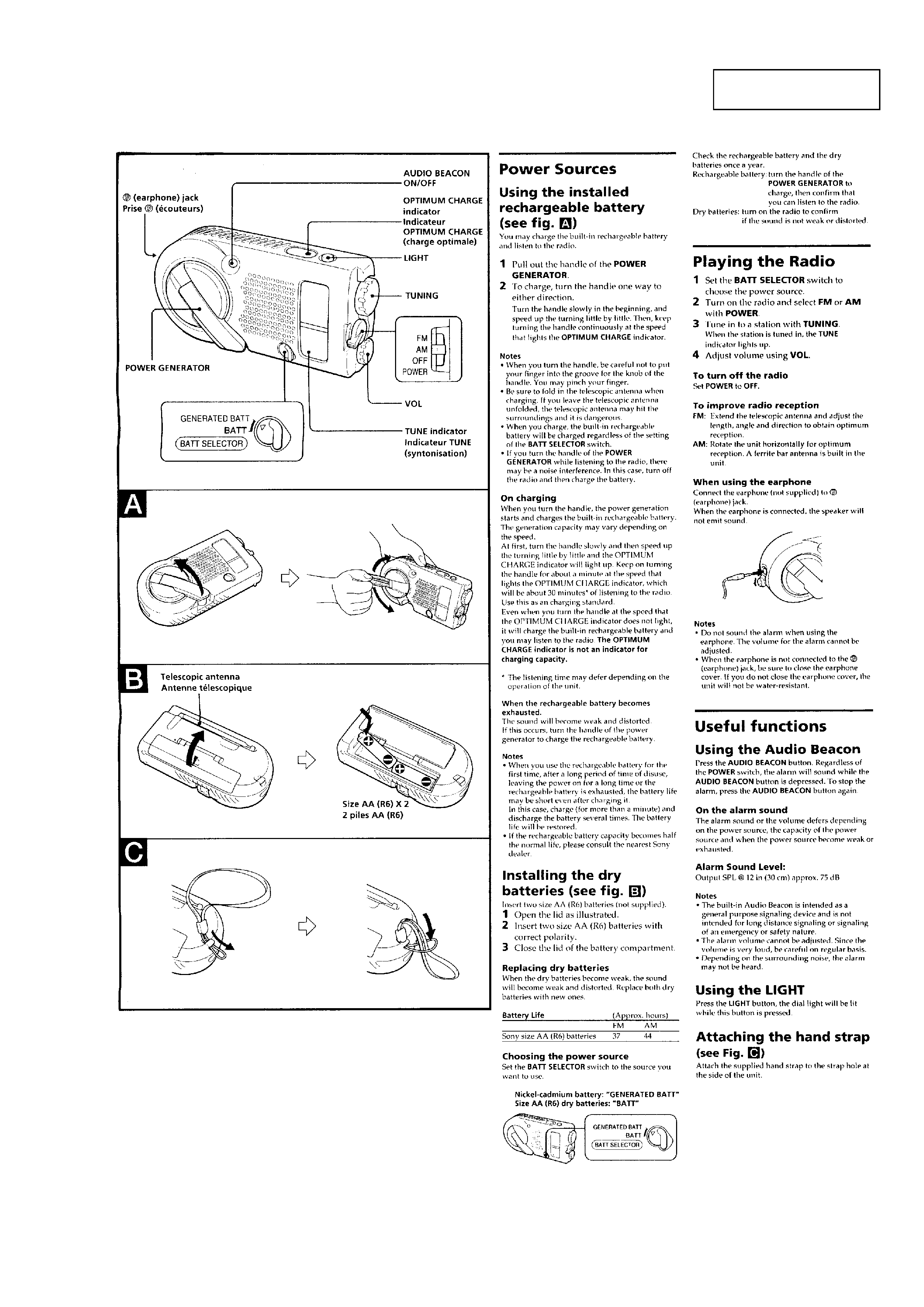
Self-powered emergency radio
· You may use the radio right away by turning the
handle of the power generator, which charges the
built-in nickel-cadmium (Ni-Cd) rechargeable
battery. --Hand generating function
· You may also use size AA (R6) dry batteries (not
supplied).
· Audio Beacon that alerts the surroundings.
· Useful dial light when tuning in the dark.
· Water-resistant for all weather operation*.
* Do not emmerse in water
This product is designed to be water-resistant,
but should not be emmersed in water or come in
continuous contact with water.
Before installing the batteries, be sure to wipe off
drops of water on the unit.
FEATURES
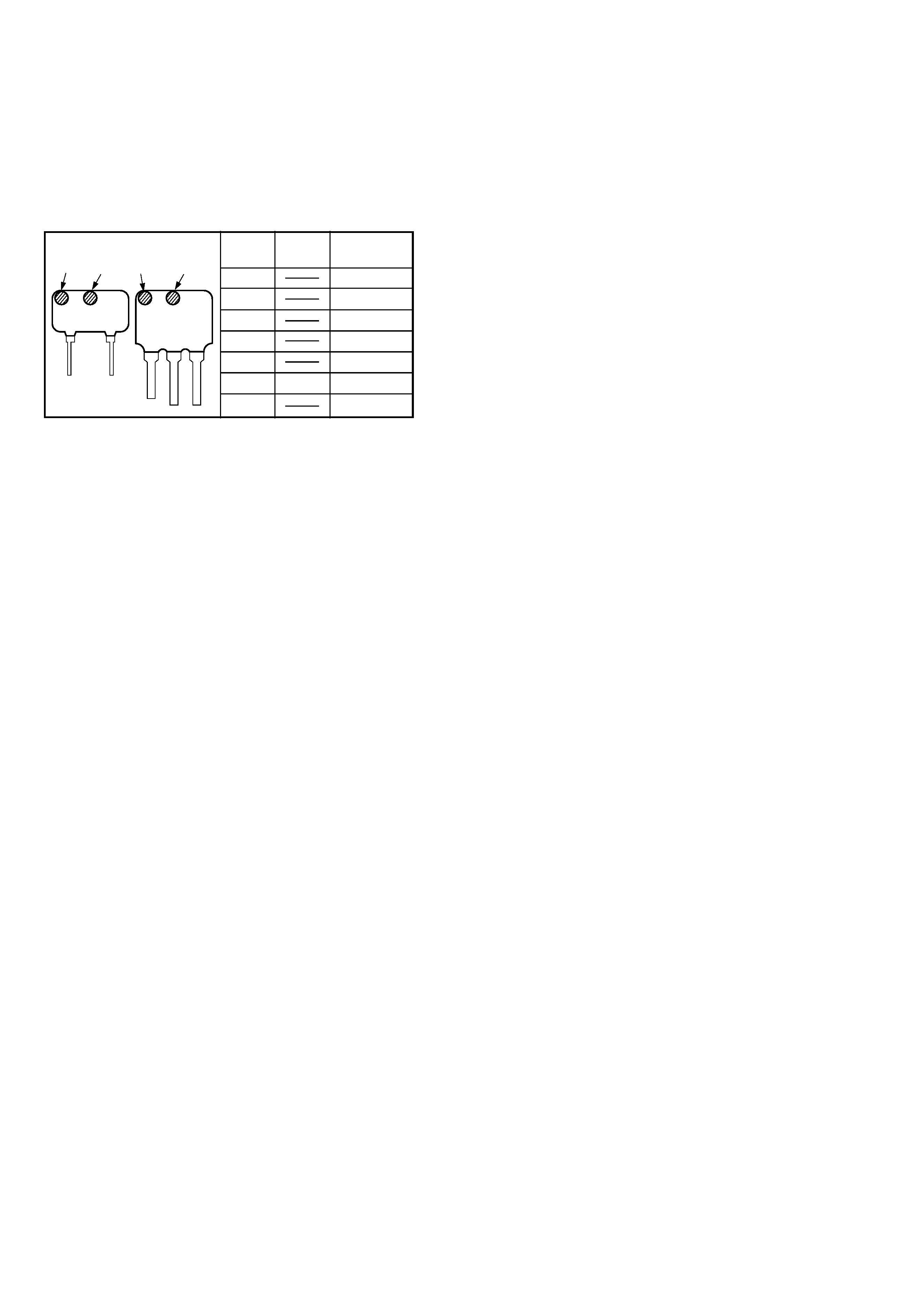
2
mark1
mark2
Center
Frequency
red
10.70 MHz
blue
10.67 MHz
orange
10.73 MHz
black
10.64 MHz
white
10.76 MHz
white
white
10.75 MHz
yellow
10.79 MHz
HOW TO CHANGE THE CERAMIC FILTERS
This model is used two ceramic filters of CF1 and CF3.
You must use same type of color marked ceramic filters in order to
meet same specifications.
Therefore, the ceramic filter must change two pieces together since
it's supply two pieces in one package as a spare parts.
TABLE OF CONTENTS
1. GENERAL
Power Sources ........................................................................ 3
Playing the Radio ................................................................... 3
Useful functions ..................................................................... 3
2. SERVICE NOTE ............................................................... 4
3. DISASSEMBLY
3-1. Cabinet (Rear) Assy ........................................................... 5
3-2. Main Board Assy ................................................................ 5
3-3. Main Board ........................................................................ 6
3-4. Pointer Setting .................................................................... 6
4. ELECTRICAL ADJUSTMENTS ................................. 7
5. DIAGRAMS
5-1. Printed Wiring Boards ........................................................ 9
5-2. Schematic Diagram .......................................................... 11
6. EXPLODED VIEWS
6-1. Cabinet (Rear) Section ..................................................... 13
6-2. Cabinet (Front) Section .................................................... 14
7. ELECTRICAL PARTS LIST ................................... 15
mark1 mark2
mark1 mark2
CF3
CF1
3
SECTION 1
GENERAL
This section is extracted
from instruction manual.
4
SECTION 2
SERVICE NOTE
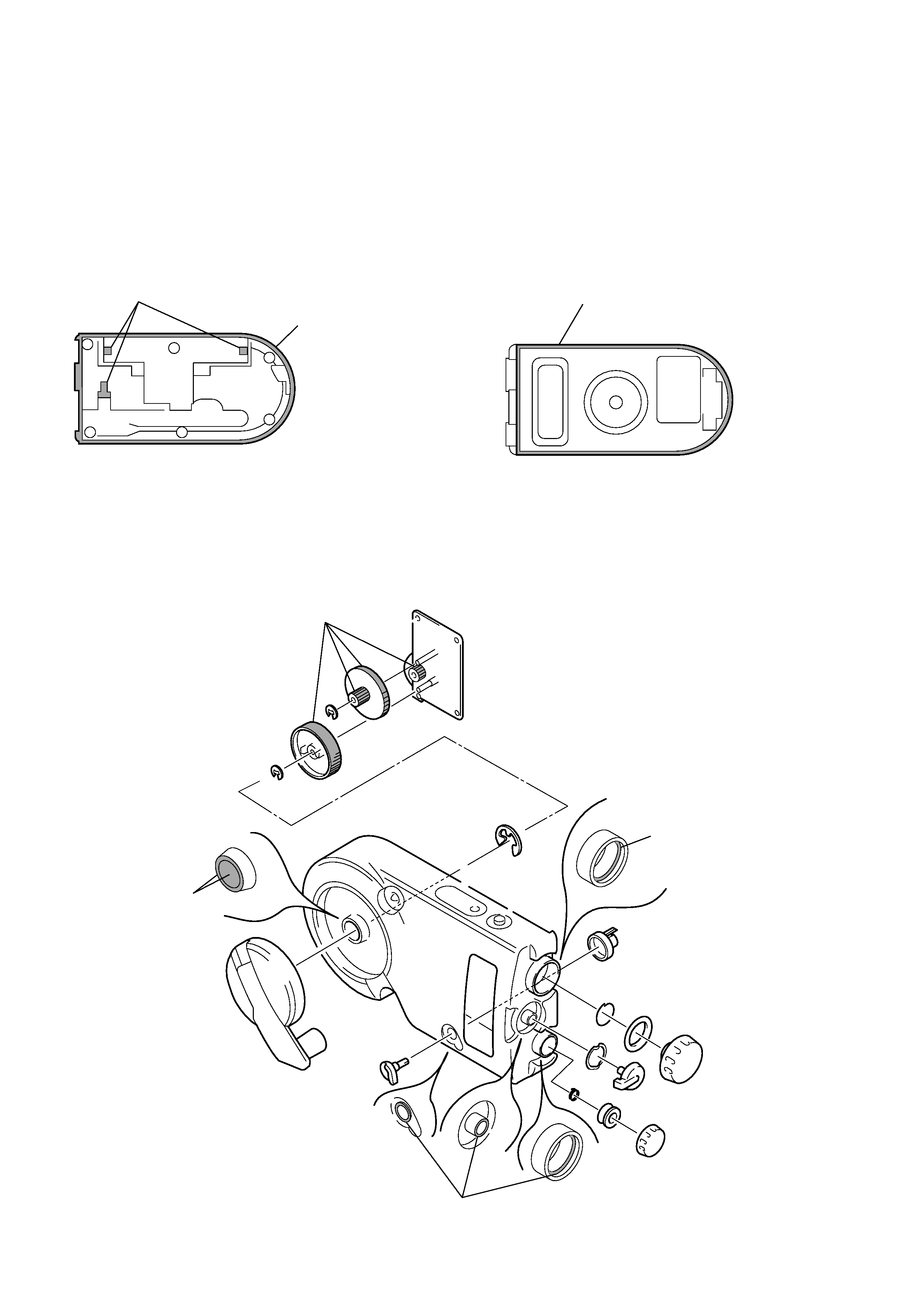
· Moisture Resistant Treatment
Be sure to perform the following work when the cabinet,
telescopic antenna and knobs have been replaced in servicing :
Apply SONY grease SGL-505 (7-662-010-04) to all around the
rib of the cabinet (rear) with an applicator or other means. Also,
apply sealant TSE392-W (7-432-950-03) to the telescopic antenna
mounting points on the cabinet (rear), the battery terminals, and
all around the rib of the cabinet (front) assy.
sealant TSE392-W (7-432-950-03)
SONY grease
SGL-505
(7-662-010-04)
sealant TSE392-W (7-432-950-03)
Apply SONY grease SGL-505 (7-662-010-04) to the knobs and
gears at the points specified in the figure with an applicator or
other means.
cabinet (rear)
cabinet (front) assy
grease applying
points (gear)
grease applying
points
cabinet (front)
grease applying
points
cabinet (front)
grease applying points
cabinet (front)
5
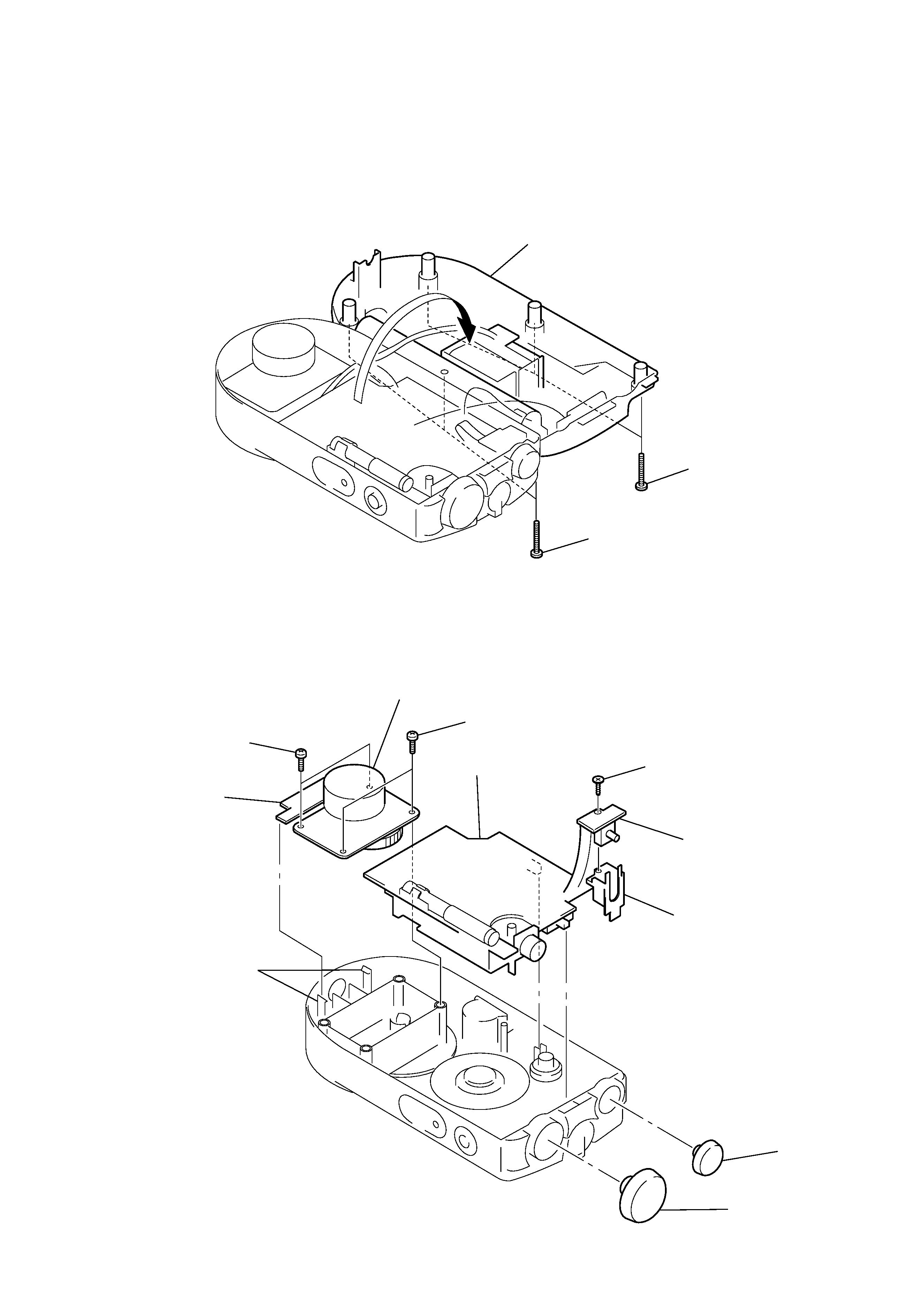
Note : Follow the disassembly procedure in the numerical order given.
3-1. CABINET (REAR) ASSY
1 Open the battery case lid.
3-2. MAIN BOARD ASSY
4 cabinet (rear) assy
3 tapping screws
(bind 2x20)
2 tapping screws
(bind 2x20)
3 PTP 3x10
5 generator
4 PTP 3x10
!¡ MAIN board assy
8 screw (M1.7)
9 VOLUME board
!º holder (VOL)
7 JACK board
6 claws
2 knob (VOL)
1 knob (TUNING)
Note for installation :
When installing the MAIN board assy,
align the two slide switches with the levers.
SECTION 3
DISASSEMBLY