1
SERVICE MANUAL
AEP Model
ICF-703/703L
UK Model
ICF-703L
ICF-703/703L
FM/AM RADIO
ICF-703
FM/MW/LW 3 BAND RADIO
ICF-703L
(Photo: ICF-703L (BLACK))
SPECIFICATIONS
Frequency range:
Italy
Band
ICF-703
ICF-703L
FM
87.5 - 108.0 MHz
--
AM
526.5 - 1606.5 kHz
--
Other countries
Band
ICF-703
ICF-703L
FM
87.5 - 108.0 MHz
87.5 - 108.0 MHz
SW
--
--
AM (MW)
530 - 1605 kHz
530 - 1605 kHz
LW
--
153 - 255 kHz
Speaker
Approx. 10.2 cm (4 1/8 inches) dia. 8 ohms
Power output
430 mW (at 10 % harmonic distortion)
Output
v
jack (ø 3.5 mm minijack)
Power requirements
With the supplied AC power cord:
220 - 230 V AC, 50 Hz
With four R6 (size AA) batteries: 6V DC
Dimensions
Approx. 265
× 137 × 69 mm (w/h/d)
(10 1/2
× 5 1/2 × 2 3/4 inches) incl. projecting parts
and control with carrying handle pushed in.
Mass
Approx. 1019 g (2 lb 4 oz) incl. batteries
Supplied accessory
AC power cord (1)
Design and specifications are subject to change without
notice.
Ver 1.0 2000. 03
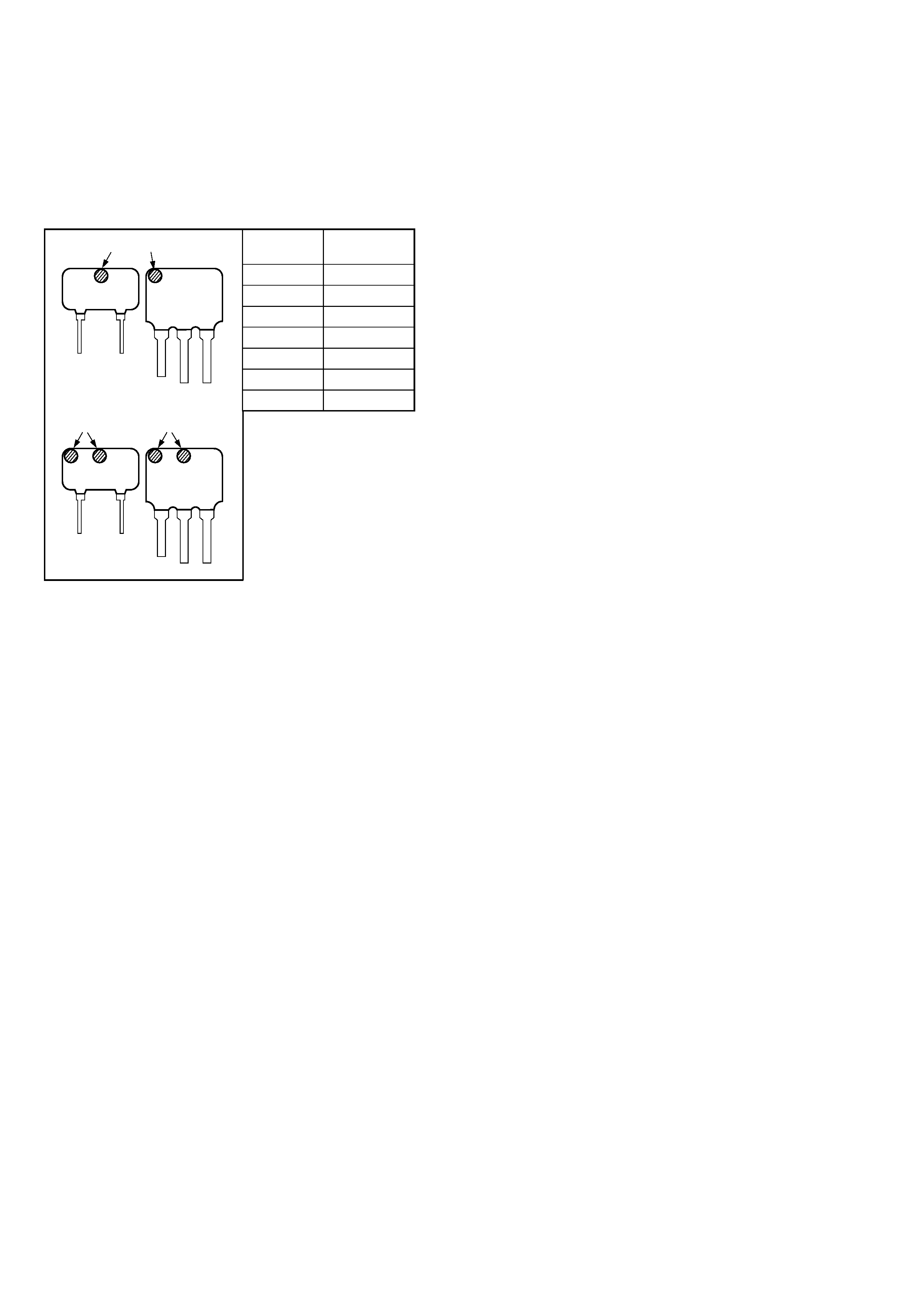
2
mark
Center
Frequency
red
10.70 MHz
blue
10.67 MHz
orange
10.73 MHz
black
10.64 MHz
white
10.76 MHz
white/white
10.75 MHz
yellow
10.79 MHz
HOW TO CHANGE THE CERAMIC FILTERS
This model is used two ceramic filters of CF2, CF3 and CF4.
You must use same type of color marked ceramic filters in order to
meet same specifications.
Therefore, the ceramic filter must change two pieces together since
it's supply two pieces in one package as a spare parts.
mark
mark
· white/white only
CF2
CF3
CF4
mark
mark
CF3
CF2
CF4
Notes on Chip Component Replacement
· Never reuse a disconnected chip component.
· Notice that the minus side of a tantalum capacitor may be
damaged by heat.
SAFETY-RELATED COMPONENT WARNING!!
COMPONENTS IDENTIFIED BY MARK 0 OR DOTTED LINE
WITH MARK 0 ON THE SCHEMATIC DIAGRAMS AND IN
THE PARTS LIST ARE CRITICAL TO SAFE OPERATION.
REPLACE THESE COMPONENTS WITH SONY PARTS WHOSE
PART NUMBERS APPEAR AS SHOWN IN THIS MANUAL OR
IN SUPPLEMENTS PUBLISHED BY SONY.
3
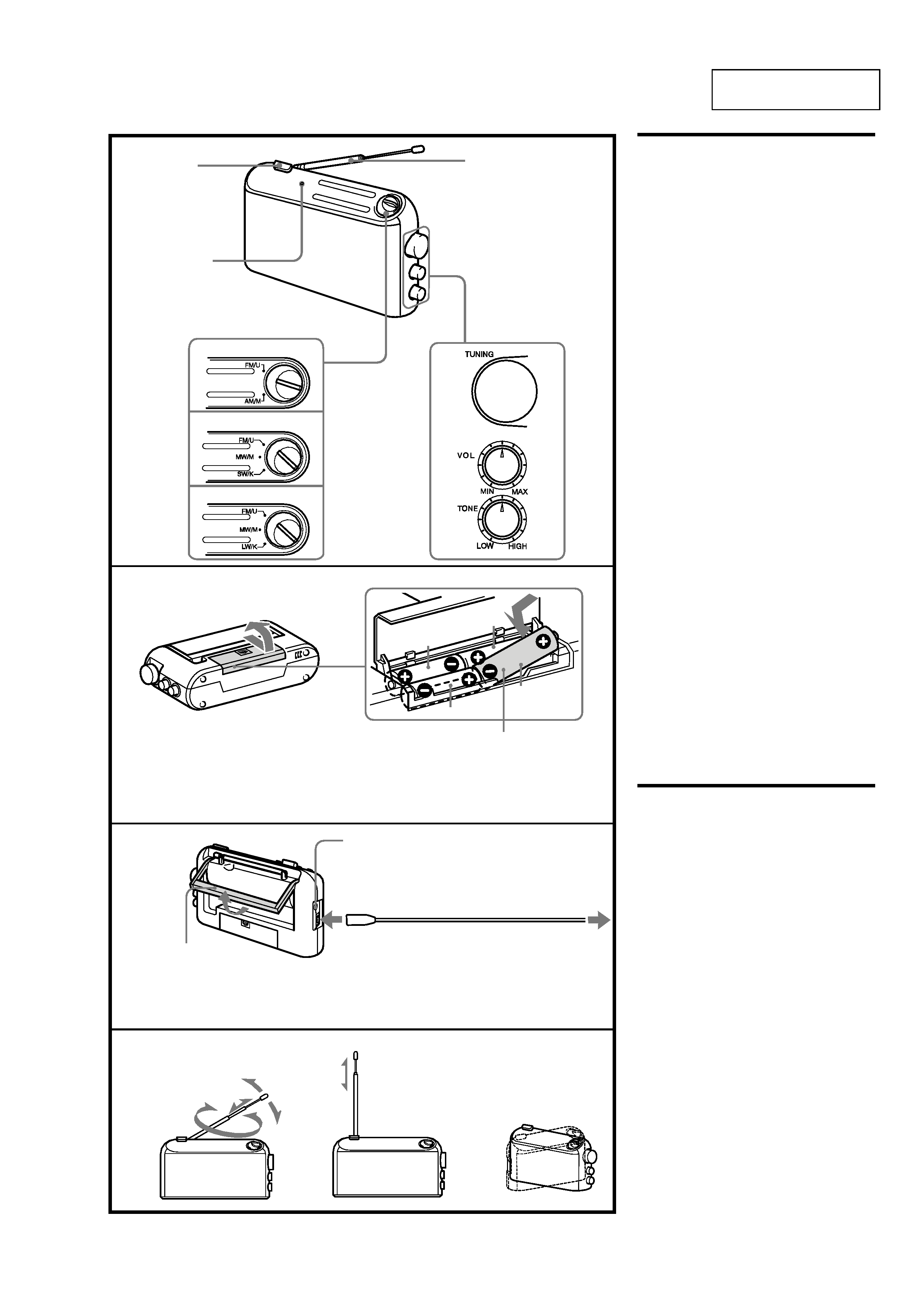
SECTION 1
GENERAL
This section is extracted
from instruction manual.
A
B
C
OPERATION
($ON/4STANDBY)
Insert the # side of the battery first.
Insérez le côté # de la pile en premier.
Batterie mit der # Seite zuerst einlegen.
Inserte en primer lugar el lado
# de las pilas
Inserire prima il lato
# della pila.
R6 (size AA) battery x 4
pile R6 (format AA) x 4
Mignonzelle (R6/AA) x 4
pila R6 (tomaño AA) x 4
pila R6 (formato AA) x 4
ICF-703
ICF-703S
ICF-703L
Choosing Power
Sources
Batteries (See Fig. A)
1 Open the lid of the battery case.
Slide fully in the direction of the arrow (B) on
the lid and lift it. Do not force to open it.
Doing so may damage the unit.
2 Insert four R6 (sizeAA) batteries (not
supplied) with correct polarity.
3 Close the lid.
Battery life
Using Sony LR6(size AA) alkaline batteries:
Approx. 100 hours
Using Sony R6 (size AA) batteries:
Approx. 35 hours
Replacing batteries
When the sound becomes weak or distorted,
replace all the batteries with new ones.
Notes on batteries
· Insert the batteries with correct polarity.
· Do not charge the dry batteries.
· Do not use different types of batteries at the
same time.
· When you replace the batteries, replace all with
new ones.
· When the unit is not being used for a long
period of time, remove the batteries to avoid
damage from battery leakage and corrosion.
· If a battery leakage occurs, wipe the battery
compartment
with a soft cloth before inserting
new ones.
House Current (See Fig.B)
1 Connect the AC power cord supplied to
the AC IN jack of the radio.
2 Plug into a wall outlet.
Operating the Radio
1 Press OPERATION ( $) to turn on the
radio.
2 Select a desired band, and tune in a
station using TUNING.
TUNE (tuning) indicator lights up
when a station is tuned in.
3 Adjust the volume using VOL.
4 Adjust the tone to your preference
using TONE.
To obtain clear treble, turn to "HIGH".
To reinforce bass, set to "LOW".
· To turn off the radio, press OPERATION (4).
· To listen with an earphone connect the
earphone to the
v
(earphone) jack.
The spearker is deactivated when an earphone
is connected.
· To improve Receiving condition (See Fig.C )
FM: Extend the telescopic antenna and adjust
the length and angle for the best reception.
SW: Extend the telescopic antenna vertically.
AM(MW)/LW : Since the reception is affected
by the direction of the radio, rotate the unit
horizontally for optimum reception.
Telescopic antenna
Antenne télescopique
Teleskopantenne
Antena telescópica
Antenna telescopica
TUNE indicator
Indicateur TUNE
TUNE-Anzeige
Indicador de sintonia (TUNE)
Indicatore TUNE
AC power cord (supplied)
Cordon d'alimentation secteur
Netzkabel (mitgeliefert)
Cable de alimentación de CA (suministrado)
Cavo di alimentazione CA in dotazione
Carrying handle
Poigné de transport
Tragegriff
Asa de transporte
Maniglia di trasporto
v
jack
Prise v
v
-Buchse
Toma v
Presa v
AM (MW)/LW
AM (PO)/GO
FM
UKW
SW
OC
KW
AC IN
1
2
3
4
4
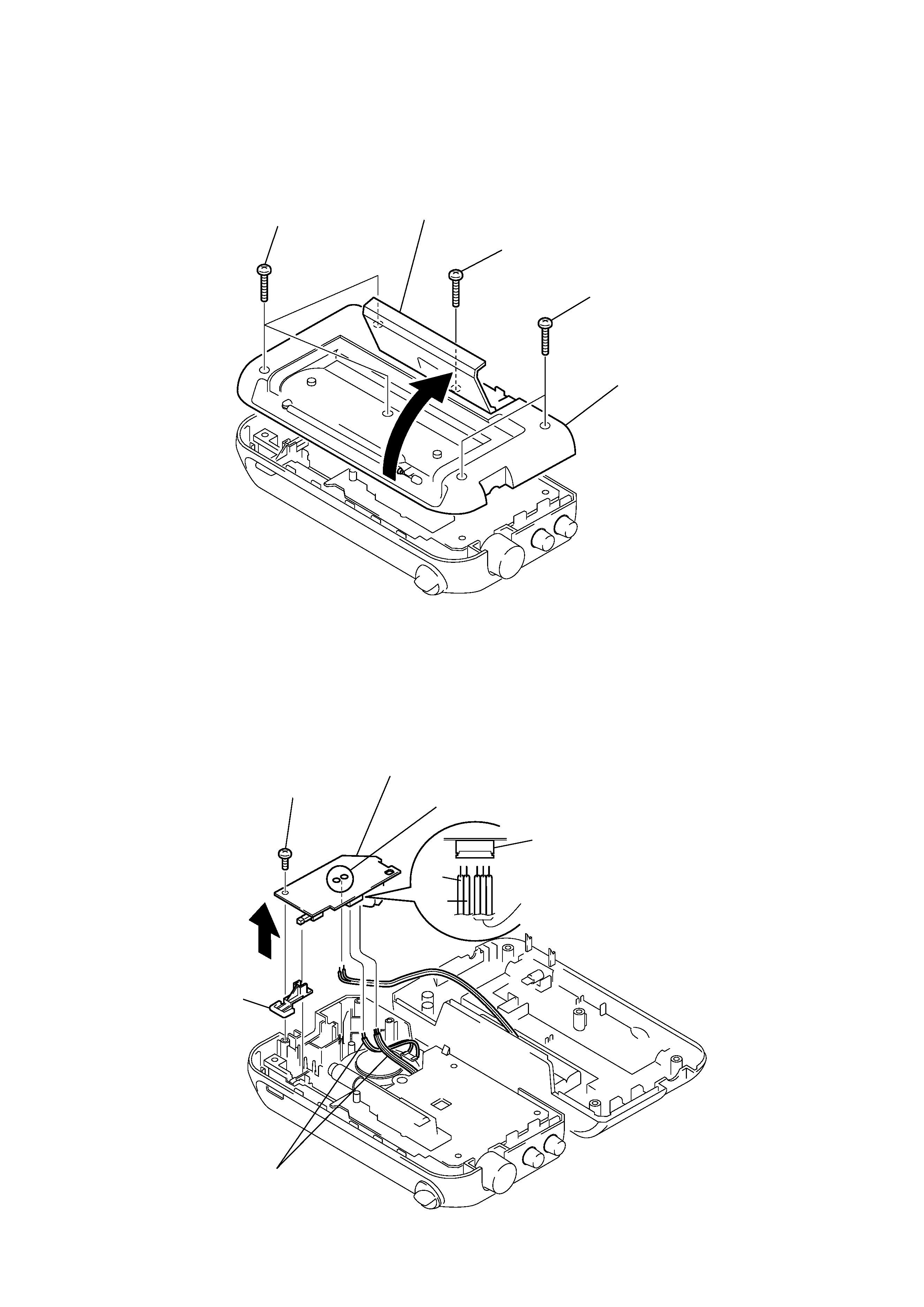
Note : Follow the disassembly procedure in the numerical order given.
2-1. CABINET (REAR)
2-2. POWER BOARD
SECTION 2
DISASSEMBLY
1
lid, battery case
2
BTP 3x16
3
BTP 3x16
4
BTP 3x16
5
cabinet (rear)
1
BTP 3x10
5
button (power)
4
Removal the solders.
CN401
BLU
BLK
PNK
6
POWER board
3
CN401
2
5
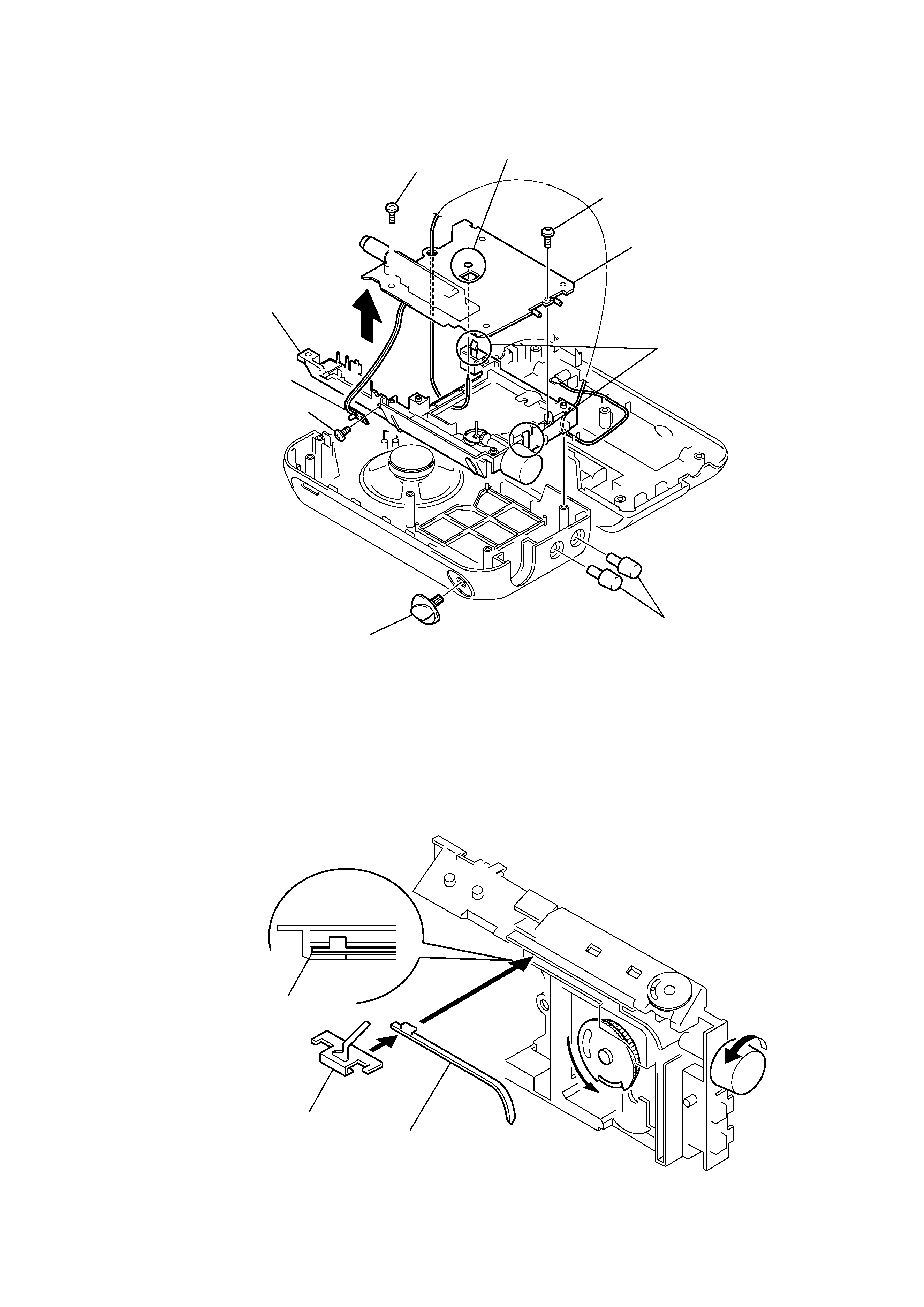
2-3. MAIN BOARD, LED BOARD
2-4. SETTING THE POINTER
1
knob (control)
8
BTP 3x10
9
BTP 3x10
7
claws
qa
MAIN board
5
BTP 2.6x5
6
LED board
2
knob (band)
3
chassis
0
4
Removal the solder.
1
rack (pointer)
rack (pointer)
2
pointer
· Setting the Pointer
A
1. Turn the Knob (Tuning) in the direction of A until it is stopped.
2.Place the rack as shown in the figure.
3.Mount the pointer.