Ver 1.0 1999.08
MICROFILM
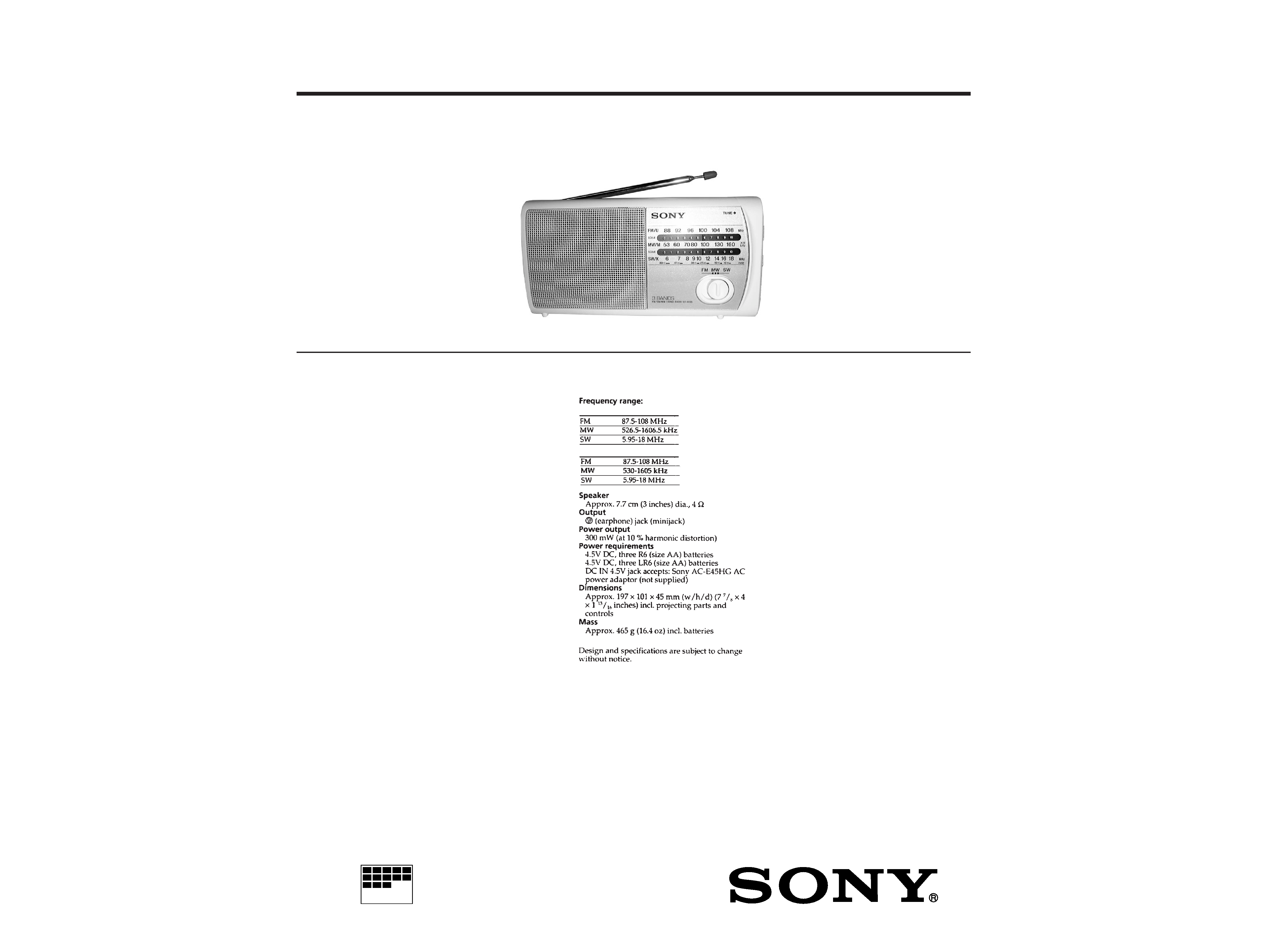
ICF-403S
SERVICE MANUAL
FM/MW/SW 3 BAND RADIO
SPECIFICATIONS
AEP Model
E Model
Australian Model
Saudi Arabia model
AEP, Australian model
2
Specifications ........................................................................... 1
1. GENERAL
Location and Function of Controls .................................... 2
2. DISASSEMBLY
2-1. Cabinet (Rear) ............................................................. 3
2-2. Cabinet (Front) ........................................................... 3
2-3. Main Board, Chassis ................................................... 4
3. DIAL POINTER INSTALLATION ........................... 5
4. ELECTRICAL ADJUSTMENTS ............................. 6
5. DIAGRAMS
5-1. Printed Wiring Boards ................................................ 7
5-2. Schematic Diagram ..................................................... 9
6. EXPLODED VIEWS ................................................... 11
7. ELECTRICAL PARTS LIST ................................... 13
Flexible Circuit Board Repairing
· Keep the temperature of the soldering iron around 270°C during
repairing.
· Do not touch the soldering iron on the same conductor of the
circuit board (within 3 times).
· Be careful not to apply force on the conductor when soldering or
unsoldering.
Notes on chip component replacement
· Never reuse a disconnected chip component.
· Notice that the minus side of a tantalum capacitor may be dam-
aged by heat.
TABLE OF CONTENTS
SECTION 1
GENERAL
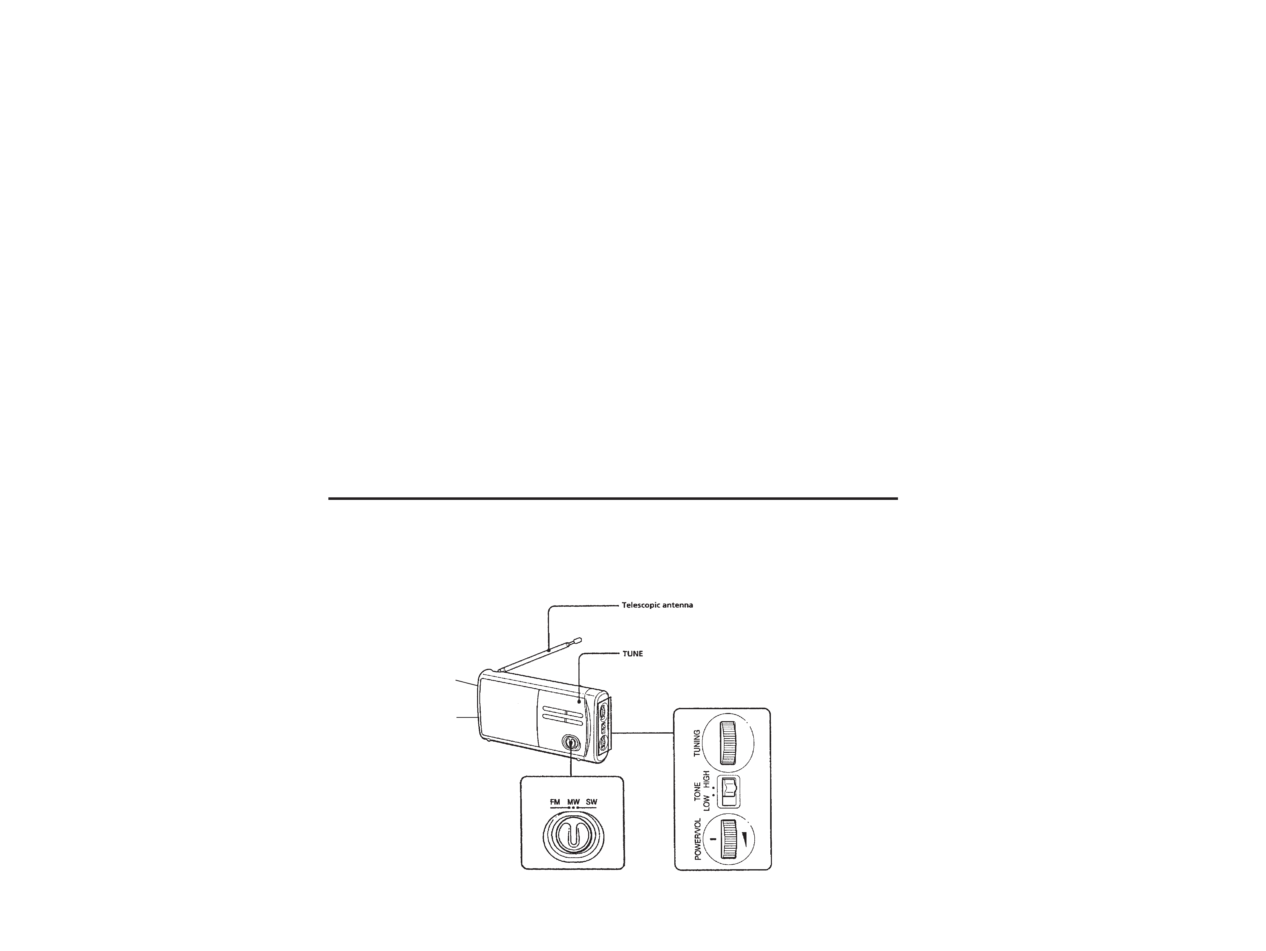
Earphone jack (
@)
DC IN 4.5V
LOCATION AND FUNCTION OF CONTROLS
3
SECTION 2
DISASSEMBLY
Note : Follow the disassembly procedure in the numerical order given.
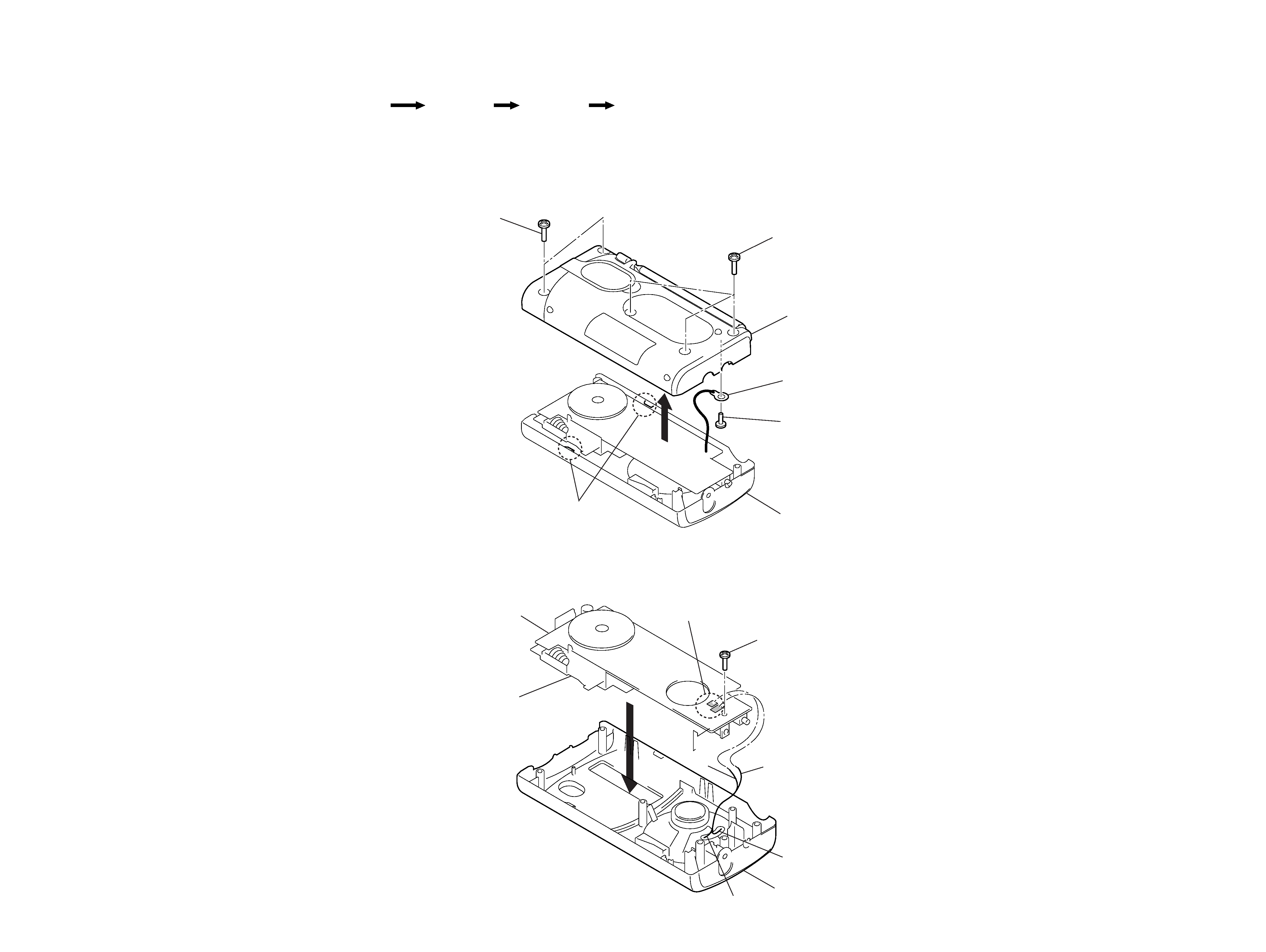
2-1. CABINET (REAR)
2-2. CABINET (FRONT)
r
The equipment can be removed using the following procedure.
Cabinet (Front)
Cabinet (Rear)
Set
Main board, Chassis
1 Screw
+P 2.6x8
Cabinet (front)
Black ()
Brown
(+)
Chassis
Main board
2 Remove solder
3
Black ()
Brown (+)
1 Screws
+BTP 3x12
4 Screw
+P 2.6x8
3
Lug, 3
Cabinet (rear)
Cabinet (front)
2 Claws
1 Screws
+BTP 3x12
4
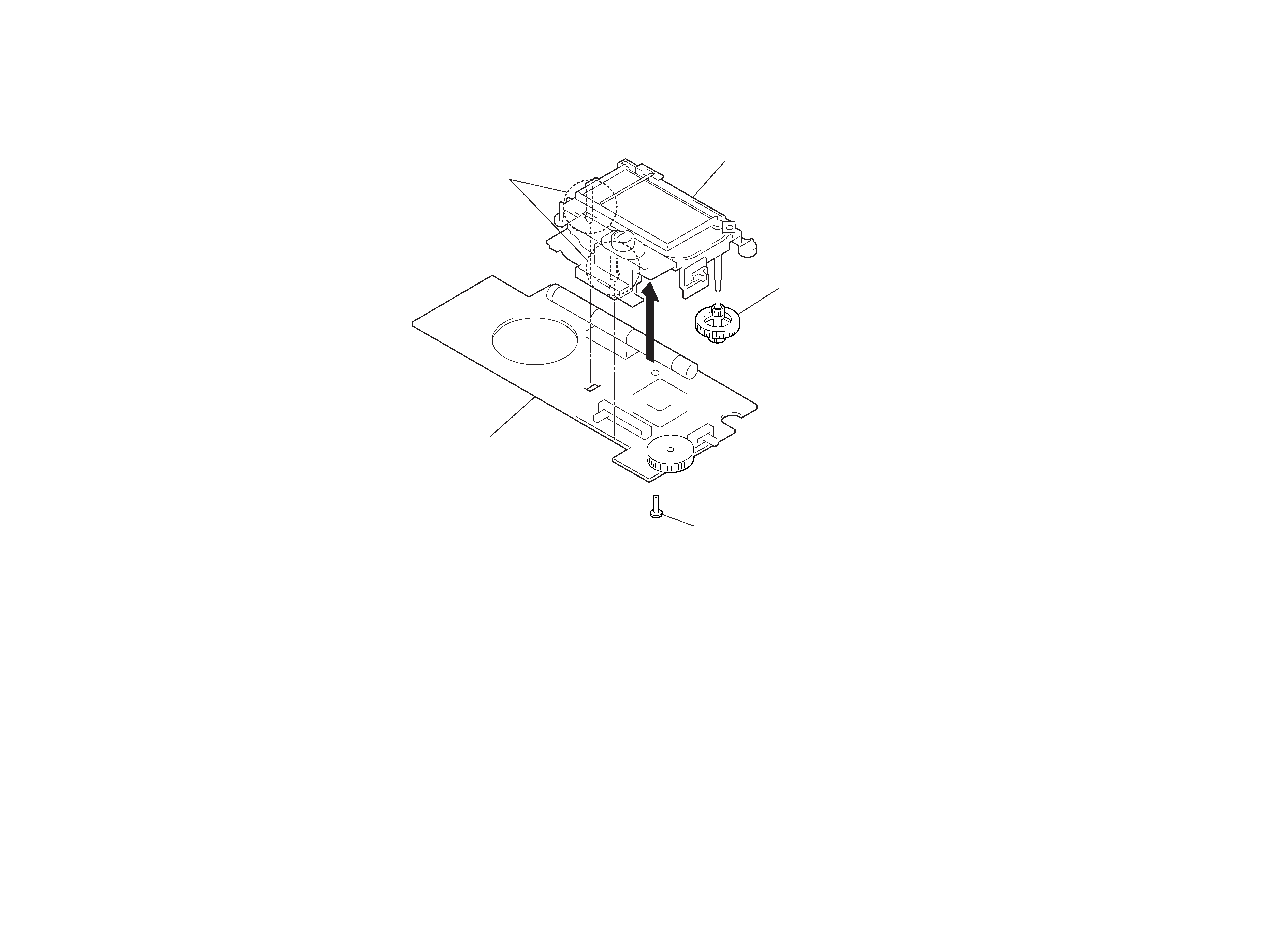
2-3. MAIN BOARD, CHASSIS
2 Claws
4 Knob(tune)
3
1 Screw
+P 2.6x8
Chassis
Main board
5
6
SECTION 3
DIAL POINTER INSTALLATION
Note : Follow the installation procedure in the numerical order given.
1 Rack
6
Rack
5 Knob (tone)
5
3 Knob (tune)
2 Pointer
Chassis
Chassis
4 Scribed line
Claws
Main board
S2
1 Insert the rack into the chassis groove.
2 Install the pointer.
3 Install the knob (tune).
4 Slide the rack and align it with the groove on the scribed
line.
5 Align the knob (tone) and the S2.
6 Install the chassis to the main board.
1 Turn the CV shaft all thye way counterclockwise.
2 Set the gear ASSY onto the CV shaft in a
direction as a figure.
3 Secure the gear ASSY with screw.
Gear (A),tuning capacitor
4
2
1
3
Stopper
Spring
(gear)
Hole
A Projection
Gear (B),tuning capacitor
B Hole
Spring (gear)
3 Screw (1.7x3)
2 Gear ASSY
1
CV shaft
Main board
Knob (tune)
1 Put a point of spring (gear) in a hole of "gear (A), tuning
capacitor" and install it.
2 Install "gear (B), tuning capacitor" in a direction as a figure.
3 Turn the "gear (B), tuning capacitor" till a position of B fits
A.
4 Hang the spring (gear) with a stopper.
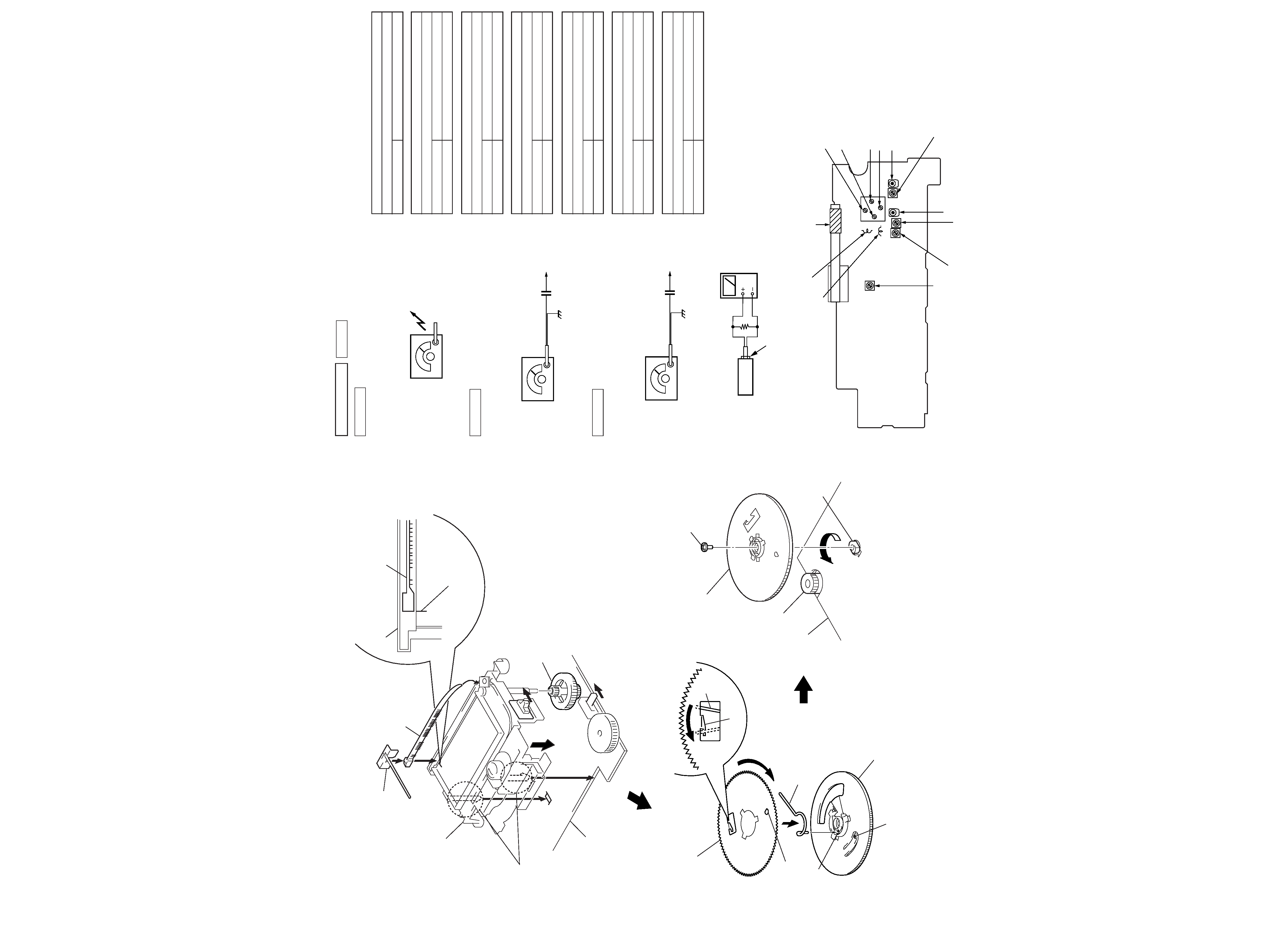
SECTION 4
ELECTRICAL ADJUSTMENTS
TUNER SECTION
MW Section
Procedure :
BAND : MW
SW Section
Procedure :
BAND : SW
FM Section
Procedure :
BAND : FM
AM RF signal
generator
30% amplitude modulation by 400Hz
signal.
Output level : as low as possible
Put the lead-wire
antenna close to
the set.
·
Repeat the procedures in each adjustment several times, and the
frequency coverage and tracking adjustments should be finally
done by the trimmer capacitors.
<
> : Saudi Arabia model
AM IF ADJUSTMENT
Adjust for a maximum reading on level meter.
T1
455kHz
MW FREQUENCY COVERAGE ADJUSTMENT
Adjust for a maximum reading on level meter.
L5
520kHz
CT4
1,650kHz
MW TRACKING ADJUSTMENT
Adjust for a maximum reading on level meter.
L1
620kHz
CT1
1,400kHz
SW FREQUENCY COVERAGE ADJUSTMENT
Adjust for a maximum reading on level meter.
L6
5.8MHz
CT6
18.5MHz
SW TRACKING ADJUSTMENT
Adjust for a maximum reading on level meter.
L2
5.8MHz
CT5
18.5MHz
FM FREQUENCY COVERAGE ADJUSTMENT
Adjust for a maximum reading on level meter.
L4
86.5MHz
<87.35MHz>
CT3
109.5MHz <108.25MHz>
FM TRACKING ADJUSTMENT
Adjust for a maximum reading on level meter.
L3
86.5MHz
<87.35MHz>
CT2
109.5MHz <108.25MHz>
L6 : SW Frequency Coverage Adjustment
CT3 : FM Frequency Coverage Adjustment
L4 : FM Frequency Coverage Adjustment
L5 : MW Frequency Coverage Adjustment
CT6 : SW Frequency Coverage Adjustment
CT4 : MW Frequency Coverage Adjustment
T1 : AM IF Adjustment
L1 : MW Tracking Adjustment
CT1 : MW Tracking Adjustment
CT2 : FM Tracking Adjustment
CT5 : SW Tracking Adjustment
L2 : SW Tracking Adjustment
L3 : FM Tracking Adjustment
Adjustment Location : Main board (Component side)
AM RF signal
generator
12PF
30% amplitude modulation by
400Hz signal.
Output level : as low as possible
telescopic
antenna
terminal
set
32
phone jack (J1)
level meter
FM RF signal
generator
22.5kHz frequency deviation by
400Hz signal.
Output level : as low as possible
telescopic
antenna
terminal
0.01
µF
0dB=1
µV