SERVICE MANUAL
Sony Corporation
Connect Company
Published by Sony Engineering Corporation
US Model
ICD-MX20/MX20VTP
Canadian Model
AEP Model
UK Model
E Model
Tourist Model
ICD-MX20
IC RECORDER
9-879-514-02
2005E16-1
© 2005.05
Ver. 1.1 2005.05
SPECIFICATIONS
ICD-MX20/MX20VTP
Recording media
Built-in flash memory 32MB/"Memory Stick
Duo", Stereo/Monaural recording
Recording time
· ST:
Approx. 1 hours 25 minutes
· STLP: Approx. 2 hours 45 minutes
· SP:
Approx. 4 hours 20 minutes
· LP:
Approx. 11 hours 45 minutes
Frequency range
· ST:
60 Hz - 13,500 Hz
· STLP: 60 Hz - 7,000 Hz
· SP:
60 Hz - 7,000 Hz
· LP:
60 Hz - 3,500 Hz
Speaker
approx. 2.8 cm (1 1/
8 in.) dia.
Power output
350 mW
Input/Output
· Microphone jack (minijack, stereo)
input for plug in power, minimum input
level 0.6 mV, 3 kilohms or lower
impedance microphone
· Headphones jack (minijack, stereo)
output for 8 - 300 ohms headphones
· USB connector
· "Memory Stick Duo" slot
· DC IN 3V jack
Playback speed control (DPC)
+100% to -50%
Power requirements
Two LR03 (size AAA) alkaline batteries: 3 V
DC
Dimensions (w/h/d) (not including projecting parts and
controls)
36.6
× 107.5 × 16.9 mm (1 1/
2 × 4
1/
4 ×
11/
16 in.)
Mass (including batteries)
96 g (3.4 oz)
Supplied accessories
Operating instructions (For the IC recorder
(1)/For the application software (1))
Stereo headphones (1)
USB connecting cable (1)
Application Software (CD-ROM) (1)
LR03 (size AAA) alkaline batteries (2)
Carrying pouch (1)
Dragon NaturallySpeaking® Preferred
(Version 8.0) CD-ROM(1) supplied only with
ICD-MX20VTP sold in the USA
Your dealer may not handle some of the above listed
optional accessories. Please ask the dealer for detailed
information.
Design and specifications are subject to change without
notice.
2
ICD-MX20/MX20VTP
TABLE OF CONTENTS
1.
GENERAL ................................................................... 3
2.
DISASSEMBLY
2-1.
Disassembly Flow ...........................................................
5
2-2.
Chassis (Microphone) Assembly .....................................
5
2-3.
Center Mic (MIC302), Side Mic (MIC301, MIC303) ....
6
2-4.
Case (Front) Assembly ....................................................
6
2-5.
Speaker (SP3001) Assembly ...........................................
7
2-6.
Case (Rear), Ornamental Belt (L), Ornamental Belt (R)
7
2-7.
SWITCH Board ...............................................................
8
2-8.
MAIN Board, Switch Unit ..............................................
8
2-9.
AUDIO Board, MEMORY Board ...................................
9
3.
TEST MODE ............................................................... 10
4.
DIAGRAMS
4-1.
Block Diagram MAIN Section-1 ............................. 13
4-2.
Block Diagram MAIN Section-2 ............................. 14
4-3.
Block Diagram PANEL Section ............................... 15
4-4.
Printed Wiring Board MAIN Board (Side A) ........... 16
4-5.
Printed Wiring Board MAIN Board (Side B) ........... 17
4-6.
Schematic Diagram MAIN Board (1/4) ................... 18
4-7.
Schematic Diagram MAIN Board (2/4) ................... 19
4-8.
Schematic Diagram MAIN Board (3/4) ................... 20
4-9.
Schematic Diagram MAIN Board (4/4) ................... 21
4-10. Printed Wiring Board AUDIO Board ....................... 22
4-11. Schematic Diagram AUDIO Board .......................... 23
4-12. Printed Wiring Board MEMORY Board .................. 24
4-13. Schematic Diagram MEMORY Board ..................... 25
4-14. Printed Wiring Board SWITCH Board .................... 26
4-15. Schematic Diagram SWITCH Board ....................... 27
5.
EXPLODED VIEWS
5-1.
Case (Front) Assembly,
Chassis (MIC) Assembly Section .................................... 29
5-2.
Case (Rear) Assembly Section ........................................ 30
6.
ELECTRICAL PARTS LIST .................................. 31
Flexible Circuit Board Repairing
· Keep the temperature of the soldering iron around 270 °C
during repairing.
· Do not touch the soldering iron on the same conductor of the
circuit board (within 3 times).
· Be careful not to apply force on the conductor when soldering
or unsoldering.
Notes on chip component replacement
· Never reuse a disconnected chip component.
· Notice that the minus side of a tantalum capacitor may be
damaged by heat.
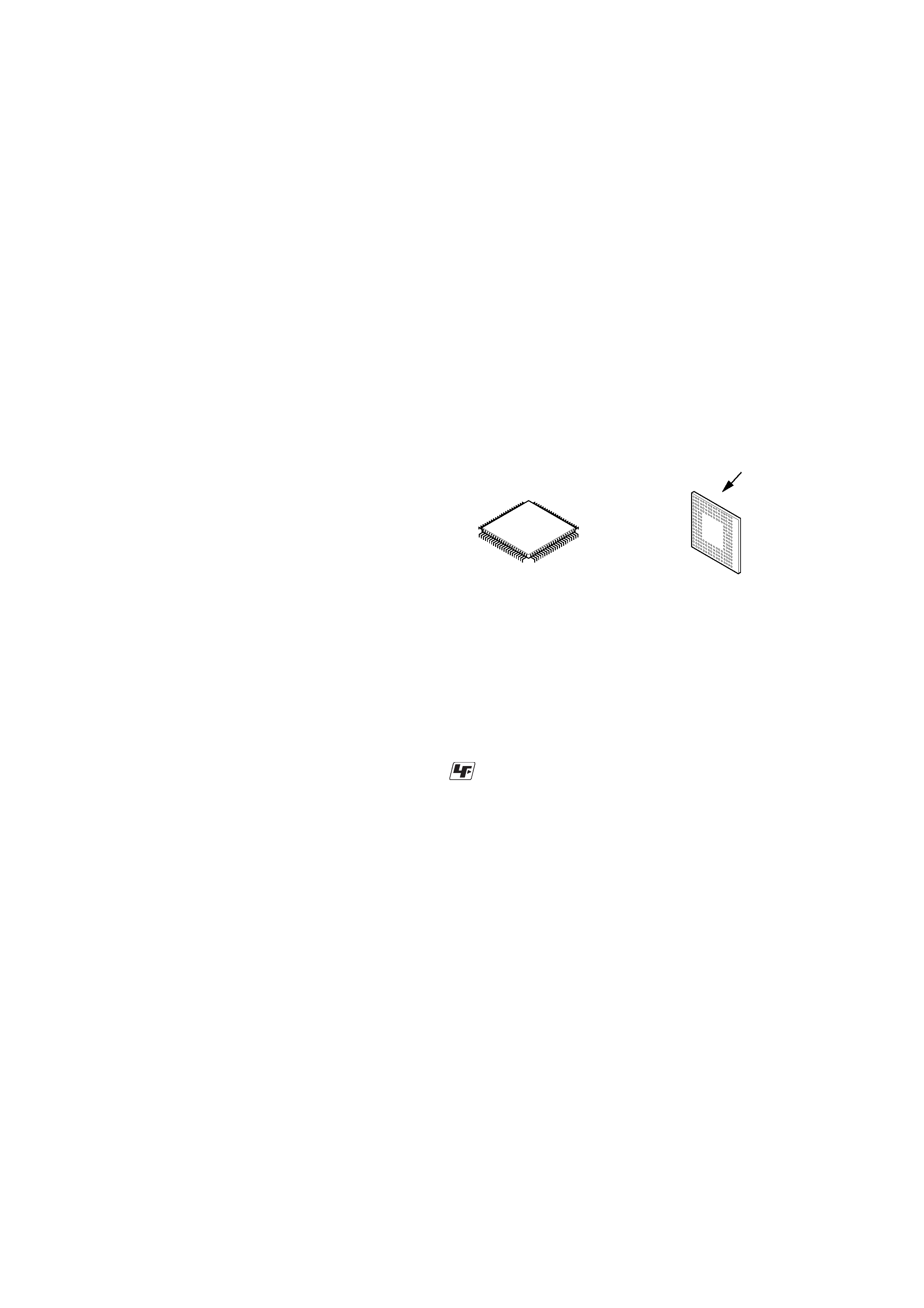
Replacement of IC6001, IC8101 and IC8201 used in this set
requires a special tool.
·The voltage and waveform of CSP (chip size package) cannot
be measured, because its lead layout is different from that of
conventional IC.
·
Lead layouts
surface
Lead layout of
conventional IC
CSP (chip size package)
UNLEADED SOLDER
Boards requiring use of unleaded solder are printed with the lead-
free mark (LF) indicating the solder contains no lead.
(Caution: Some printed circuit boards may not come printed with
the lead free mark due to their particular size)
: LEAD FREE MARK
Unleaded solder has the following characteristics.
· Unleaded solder melts at a temperature about 40 °C higher
than ordinary solder.
Ordinary soldering irons can be used but the iron tip has to be
applied to the solder joint for a slightly longer time.
Soldering irons using a temperature regulator should be set to
about 350
°C.
Caution: The printed pattern (copper foil) may peel away if
the heated tip is applied for too long, so be careful!
· Strong viscosity
Unleaded solder is more viscou-s (sticky, less prone to flow)
than ordinary solder so use caution not to let solder bridges
occur such as on IC pins, etc.
· Usable with ordinary solder
It is best to use only unleaded solder but unleaded solder may
also be added to ordinary solder. Operating instructiondd
3
ICD-MX20/MX20VTP
SECTION 1
GENERAL
This section is extracted
from instruction manual.
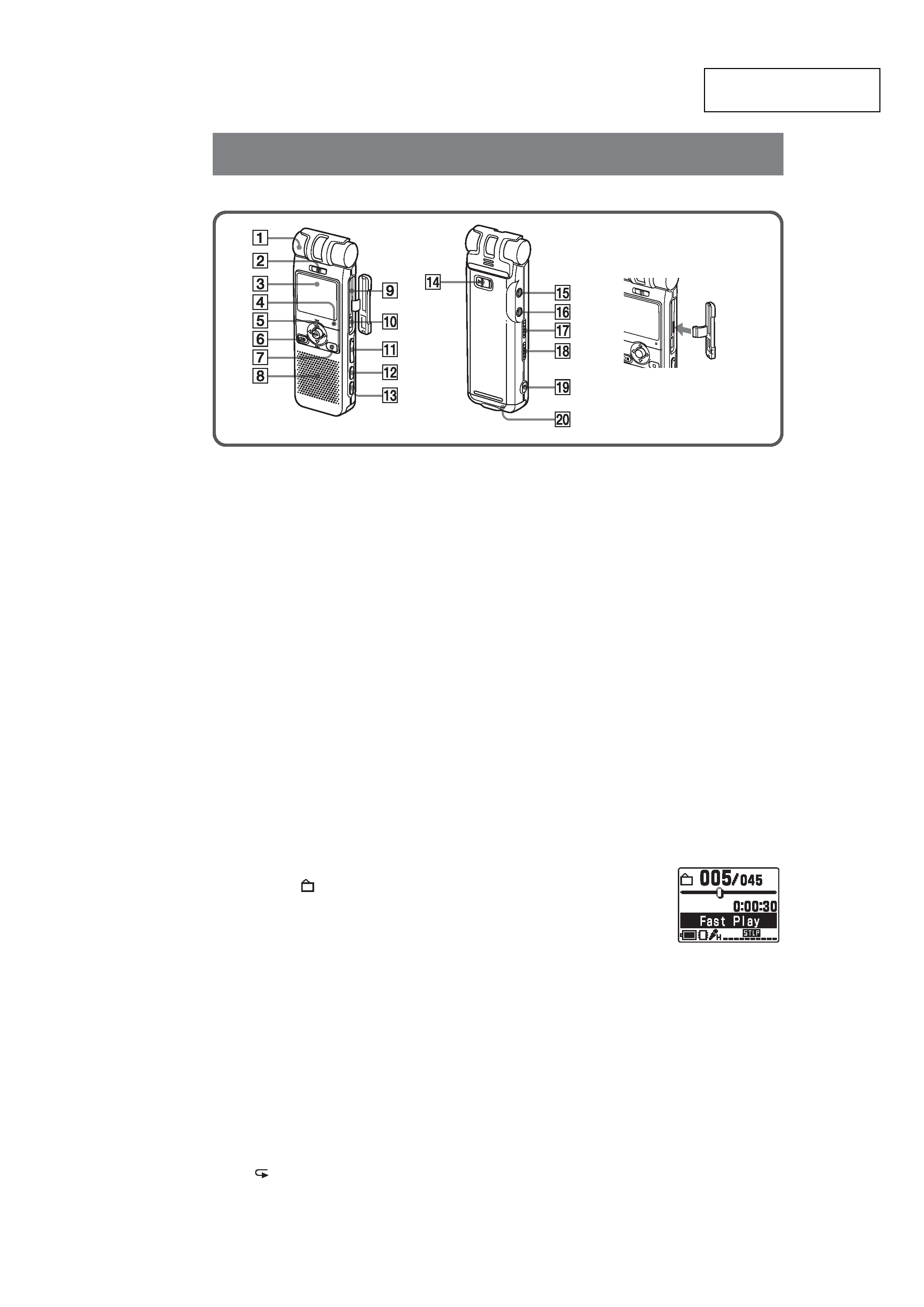
Index to Parts and Controls
Identifying the front and rear panels of the unit
1
Built-in monaural/stereo microphone
(directional/all-directional)
You can set the directivity with the DIRECTNL
switch 2, and sensitivity with the "Mic Sense" in
the menu.
2
DIRECTNL (directional) ON (MONO)/OFF switch
Slide the switch to set the directivity of the built-in
microphone 1 as follows:
ON (MONO): To record a sound centering on a
specific direction in monaural. Use this position
when you record a sound at a conference/
meeting or in a spacious place etc.
OFF: To record a sound not centering on a specific
direction (all-directional recording).
Notes
· The DIRECTNL switch is set to "ON", sound is
recorded in monaural even if you select ST or STLP
mode.
· In the ST and STLP mode, sound is recorded in higher
quality sound thanks to their higher bit rates even in
the monaural recording.
3
Display window
For the details, see "Using the display window"
below.
4
OPR (operation) indicator
The indicator lights in red during recording or in
green during playback. It flashes in red during
recording pause. During accessing the data, it lights
or flashes in red or orange. You can turn off the
indicator with the "LED" in the menu.
5
Control key
b (MENU)/B (
: folder)v(.: review)/V(>: fast
forward)/Nx (play/stop·enter)
6
zX
REC (record) /PAUSE button
Press here to start and pause recording.
7
x
STOP button
Press here to stop operation.
8
Speaker
Sound is heard when no headphones or active
speaker are connected.
9
MEMORY STICK slot
Insert the "Memory Stick Duo" or "Memory Stick
PRO Duo" here.
0
USB connector
Use the USB cable to connect a PC here.
qa
VOLUME (volume) +/ button
Adjust the playback sound with the button.
qs
DIVIDE button
Press to divide a message during playback.
qd
A-B
(repeat) button
Press to specify the beginning and ending points of
the portion to be played back repeatedly.
qf
HOLD switch
To prevent accidental operation, slide this switch to
"ON". "HOLD" will appear for 3 seconds, indicating
that all the functions of the buttons are locked.
When the HOLD function is activated during stop,
all the display will be turned off after "HOLD" is
displayed.
To cancel the HOLD function
Slide the HOLD switch to "OFF".
1
Tip
Even if the HOLD function is activated, you can stop the
alarm playback. To stop the alarm or playback, press
xSTOP. (You cannot stop usual playback.)
qg i
(headphones) jack
To monitor the recording from the built-in
microphone, connect headphones supplied or not
supplied here. You can adjust the volume with
VOLUME +/ qa, but the recording level is fixed.
Note
If you turn up the volume excessively or place the
headphones near the microphone while monitoring
recording, the microphone may pick up the sound from
the headphones, causing acoustic feedback (howling
sound).
qh m
(microphone) jack (PLUG IN POWER)
You can connect an external microphone here. When
an external microphone is connected, the built-in
microphone is automatically cut off.
qj
DPC ON/OFF switch
You can play back a message at a higher or lower
speed as follows:
ON: "Fast Play" or "Slow
Play" will be displayed
and a message is played
back at the speed specified
with the "DPC" in the
menu (between twice the
normal speed (+100%) and
half the normal speed (
50%)).
OFF: A message is played back at the normal speed.
qk
VOICE UP (Digital Voice Up) ON/OFF switch
You can make the playback sound well-balanced and
more audible by enabling the Digital Voice Up
function as follows:
ON: Digital Voice Up function is activated. Inaudible
low-level part of a recorded message is amplified
so that the overall recording is adjusted to its
optimum level.
OFF: A message is played back without Digital Voice
Up function.
Note
Depending on the area you purchased the unit, the
Digital Voice Up switch name shown on the unit may
differ.
ql
Slit for a handstrap
You can attach a handstrap (not supplied) here.
w;
Battery compartment /DC IN 3V jack
Open the compartment lid and insert two LR03 (size
AAA) alkaline batteries.
If the slot/connector lid is
accidentally detached,
attach it as illustrated.
4
ICD-MX20/MX20VTP
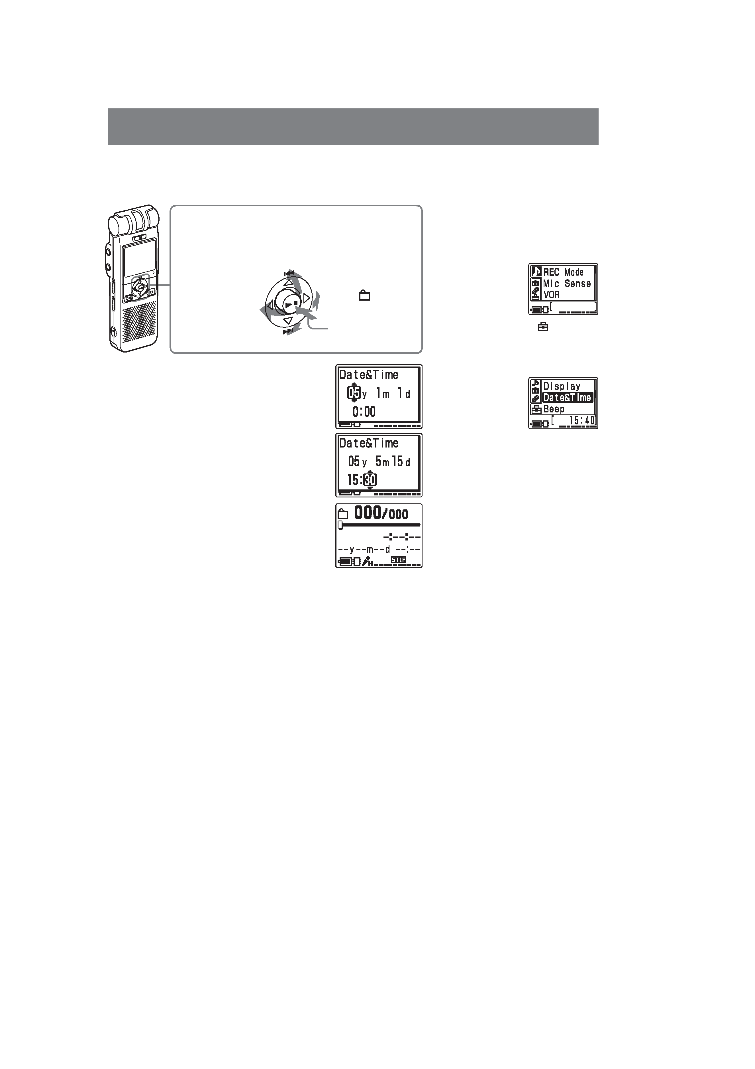
Step 2: Setting the Clock
You need to set the clock to use the alarm function or record the date and time.
When you insert batteries for the first time, or when you insert batteries after
the unit has been without batteries for a certain period of time, "Set
Date&Time" appears. Set the date and time as follows:
Press the control key upward, downward, leftward, or
rightward (v/V/b/B) to select an item, and then press
down the center (Nx) to decide on the item.
In this manual, these operations are described as follows:
Press v (.).
Press B (
;).
Press b (MENU).
Press Nx.
1 Press v/V to select the digits for the year.
v: to decrease the number
V: to increase the number
2 Press Nx.
The month digits will flash.
3 Repeat steps 1 and 2 to set the month, day,
hour, and then minutes in sequence.
To select a previous or next item
Press b for the previous item or B for the next
item.
Note
If you do not press Nx for more than one minute,
the clock setting mode is cancelled and the window
will return to normal display.
4 Press xSTOP to return to the normal
display.
Press V (>).
Note on setting the clock
Set the clock while the set is in the
stop mode.
To display the clock setting
window and current time
You can display the clock setting
window to set the date and time or
check the current time:
1Press b (MENU) to display the
menu.
2Press v/V to select
(Preferences)
and then press Nx.
3Press v/V to select "Date&Time".
The current time is displayed in the
right bottom of the display
window.
4To set the clock, press Nx to
display the "Date&Time" window
and follow the steps 1 through 4 of
the "Step 2: Setting the Clock".
Tip
This unit does not have a power on/
off switch. The display is shown at all
times.
5
ICD-MX20/MX20VTP
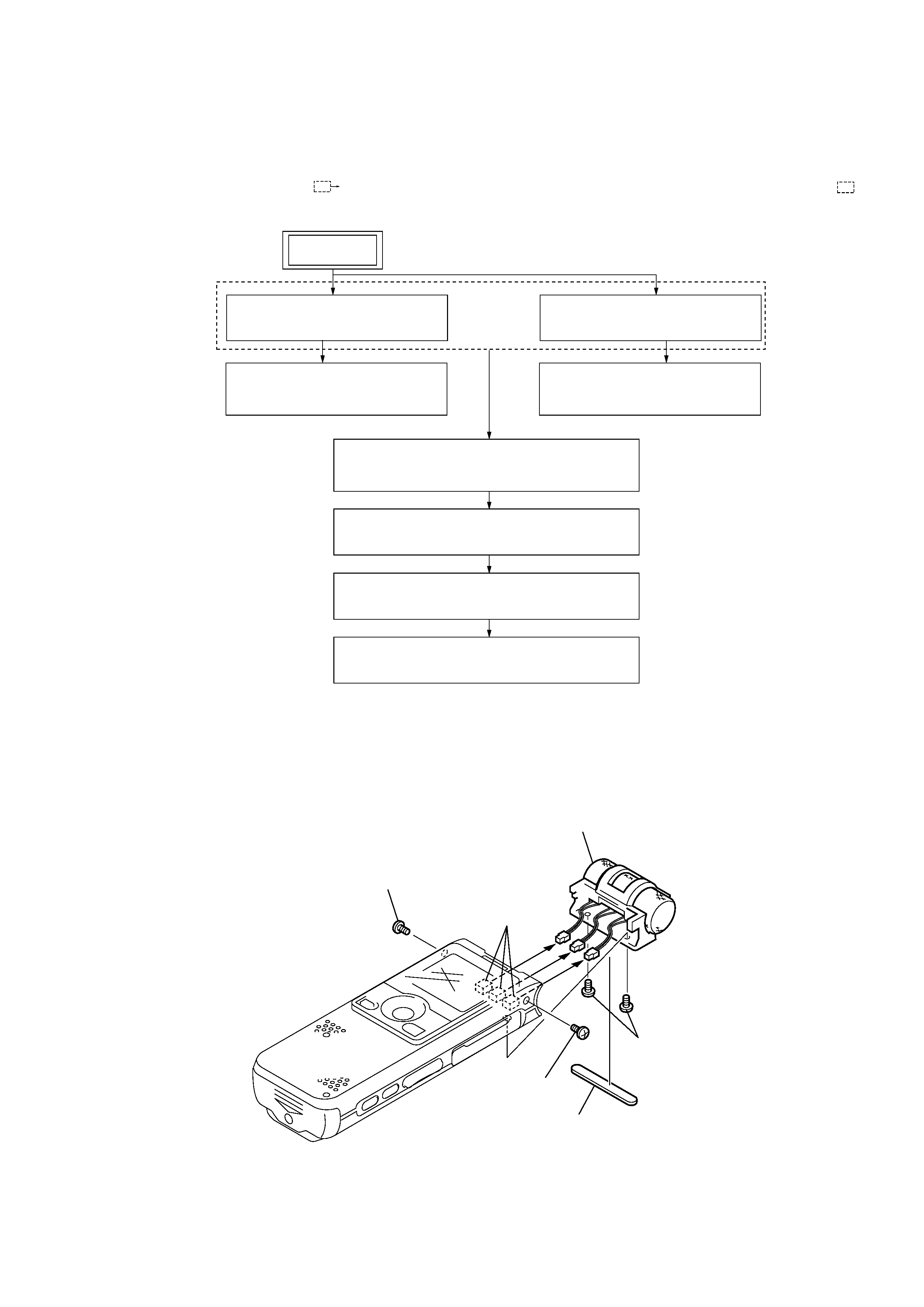
Note: Follow the disassembly procedure in the numerical order given.
2-2. CHASSIS (MICROPHONE) ASSEMBLY
SECTION 2
DISASSEMBLY
2-1. DISASSEMBLY FLOW
2-2. CHASSIS (MICROPHONE) ASSY
(Page 5)
2-4. CASE (FRONT) ASSY
(Page 6)
2-5. SPEAKER (SP3001)
(Page 7)
2-3. CENTER MIC (MIC302),
SIDE MIC (MIC301,MIC303)
(Page 6)
2-7. SWITCH BOARD
(Page 8)
2-6. CASE (REAR), ORNAMENTAL BELT (L) ,
ORNAMENTAL BELT (R)
(Page 7)
SET
2-8. MAIN BOARD, SWITCH UNIT
(Page 8)
2-9. AUDIO BOARD, MEMORY BOARD
(Page 9)
3
screw (M 1.4
× 3)
5
three connectors
6
chassis (microphone) assembly
4
screw (M 1.4)
2
two screws
(M 1.4
× 3)
1
base (microphone)
·This set can be disassembled in the order shown below.
·The dotted square with arrow (
) prompts you to move to the next job when all of the works within the dotted square (
) are
completed.