SERVICE MANUAL
Sony Corporation
Connect Company
Published by Sony Engineering Corporation
ICD-MS515
US Model
Canadian Model
AEP Model
UK Model
E Model
Tourist Model
IC RECORDER
SPECIFICATIONS
9-873-547-05
2005J16-1
© 2005.10
Recording media
"Memory Stick", Monaural recording
Recording time
Frequency response
SP: 250 Hz - 7,300 Hz
LP: 250 Hz - 3,500 Hz
Speaker
approx. 23 mm (29/
32 in.) dia.
Power output
200 mW
Input/Output
· Earphone jack (minijack) for 8 - 300 ohms
earphone/headphones
· Microphone jack (minijack, monaural)
Plug in power
Minimum input level: 0.7 mV 3 kilohms or
lower impedance microphone
· USB connector
Playback speed control
+100% to -50% (DPC)
Power requirements
Two size AAA (LR03) alkaline batteries: 3 V DC
Dimensions
34.4 x 106.3 x 18 mm (1 3/
8 x 4
1/
4 x
23/
32 in.)
(w/h/d) (not incl. projecting parts and controls)
Mass
75 g (2.7 oz) (incl. batteries and a "Memory Stick")
Supplied accessories
"Memory Stick" x 1
"Memory Stick Voice Editor" (CD-ROM) x 1
Carrying case x 1
Size AAA (LR03) alkaline battery x 2 (U.S.A. and
tourist models only)
Design and specifications are subject to change without notice.
Maximum recording time of a " Memory Stick "*
Mode** 4MB
8MB
16MB
32MB
64MB
128MB
SP
30 min.
64 min.
130 min.
264 min.
532 min.
1,067 min.
LP
82 min.
171 min.
347 min.
705 min.
1,418 min.
2,846 min.
(min.: minutes)
* When using each "Memory Stick" for use with ICD-MS515 only and by the
initial setting with three folders.
**The initial setting is SP mode.
Ver. 1.4 2005.10
2
ICD-MS515
TABLE OF CONTENTS
Flexible Circuit Board Repairing
· Keep the temperature of the soldering iron around 270°C during
repairing.
· Do not touch the soldering iron on the same conductor of the
circuit board (within 3 times).
· Be careful not to apply force on the conductor when soldering or
unsoldering.
Notes on chip component replacement
· Never reuse a disconnected chip component.
· Notice that the minus side of a tantalum capacitor may be dam-
aged by heat.
* Replacement of IC6201, IC7102 used in this set requires a special
tool.
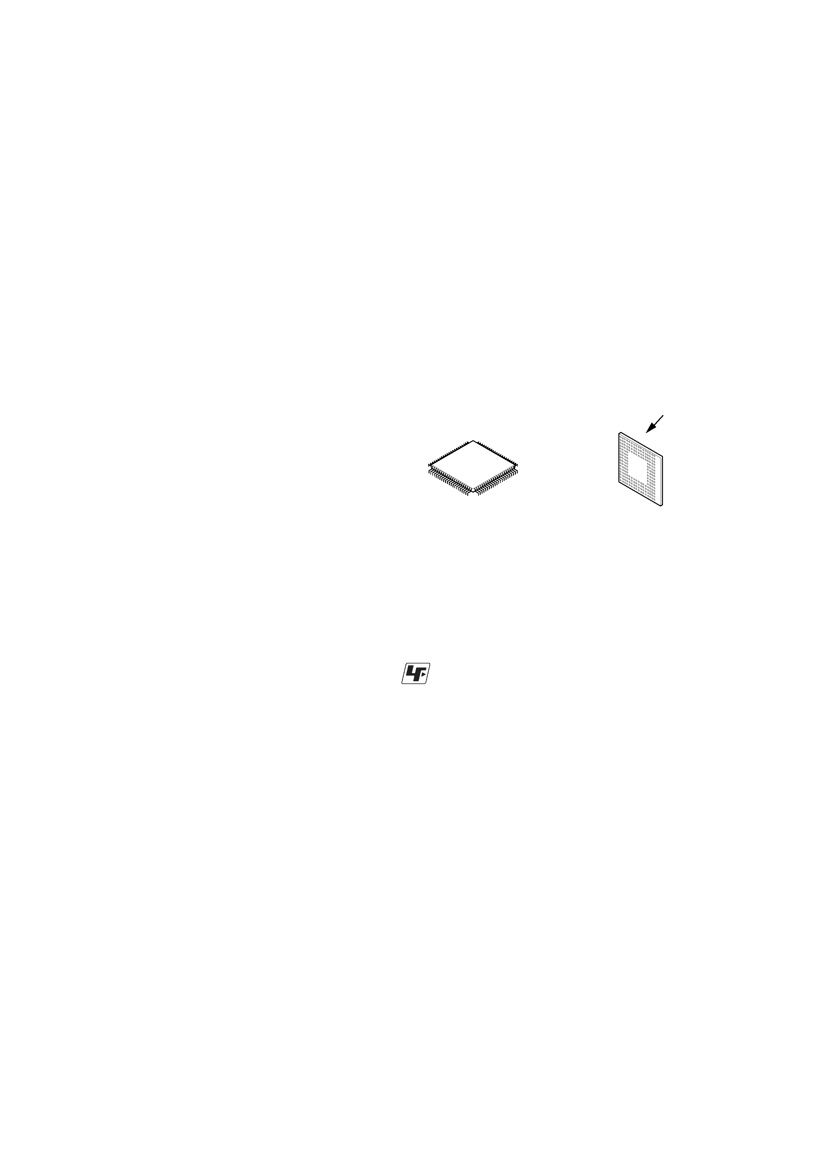
· The voltage and waveform of CSP (chip size package) cannot be
measured, because its lead layout is different from that of conven-
tional IC.
· Lead layouts
Unleaded solder
Boards requiring use of unleaded solder are printed with the lead-
free mark (LF) indicating the solder contains no lead.
(Caution: Some printed circuit boards may not come printed with
the lead free mark due to their particular size.)
: LEAD FREE MARK
Unleaded solder has the following characteristics.
· Unleaded solder melts at a temperature about 40°C higher than
ordinary solder.
Ordinary soldering irons can be used but the iron tip has to be
applied to the solder joint for a slightly longer time.
Soldering irons using a temperature regulator should be set to
about 350°C.
Caution: The printed pattern (copper foil) may peel away if the
heated tip is applied for too long, so be careful!
· Strong viscosity
Unleaded solder is more viscous (sticky, less prone to flow) than
ordinary solder so use caution not to let solder bridges occur such
as on IC pins, etc.
· Usable with ordinary solder
It is best to use only unleaded solder but unleaded solder may
also be added to ordinary solder.
surface
Lead layout of
conventional IC
CSP (chip size package)
1. GENERAL ·········································································· 3
2. DISASSEMBLY ································································ 4
2-1. Front Cabinet Section, Lid (M) Section ······················· 4
2-2. LCD Block Assy ··························································· 5
2-3. Eject Mecha Block Assy, MAIN Board ························ 6
2-4. Speaker Assy (SP3201), Microphone Unit (MIC3201),
AUDIO Board-1 ···························································· 7
2-5. Speaker Assy (SP3201), Microphone Unit (MIC3201),
AUDIO Board-2 ···························································· 8
2-6. SWITCH Board ···························································· 8
2-7. Liquid Crystal Indicator Unit ········································ 9
3. TEST MODE ···································································· 10
4. DIAGRAMS ······································································ 12
4-1. Block Diagrams ·························································· 13
4-2. Printed Wiring Board AUDIO Board ···················· 15
4-3. Schematic Diagram AOUDIO Board (1/2) ··········· 16
4-4. Schematic Diagram AOUDIO Board (2/2) ··········· 17
4-5. Printed Wiring Board MAIN Board ····················· 18
4-6. Schematic Diagram MAIN Board (1/2) ··············· 19
4-7. Schematic Diagram MAIN Board (2/2) ··············· 20
4-8. Printed Wiring Board SWITCH Board ················· 21
4-9. Schematic Diagram SWITCH Board ···················· 22
4-10. IC Block Diagrams ····················································· 23
4-11. IC Pin Function Descriptions ······································ 25
5. EXPLODED VIEWS ······················································ 30
5-1. Front Cabinet Section ················································· 30
5-2. Rear Cabinet Section ·················································· 31
5-3. Case Section ································································ 32
6. ELECTRICAL PARTS LIST ······································· 33
3
ICD-MS515
SECTION 1
GENERAL
This section is extracted from
instruction manual.
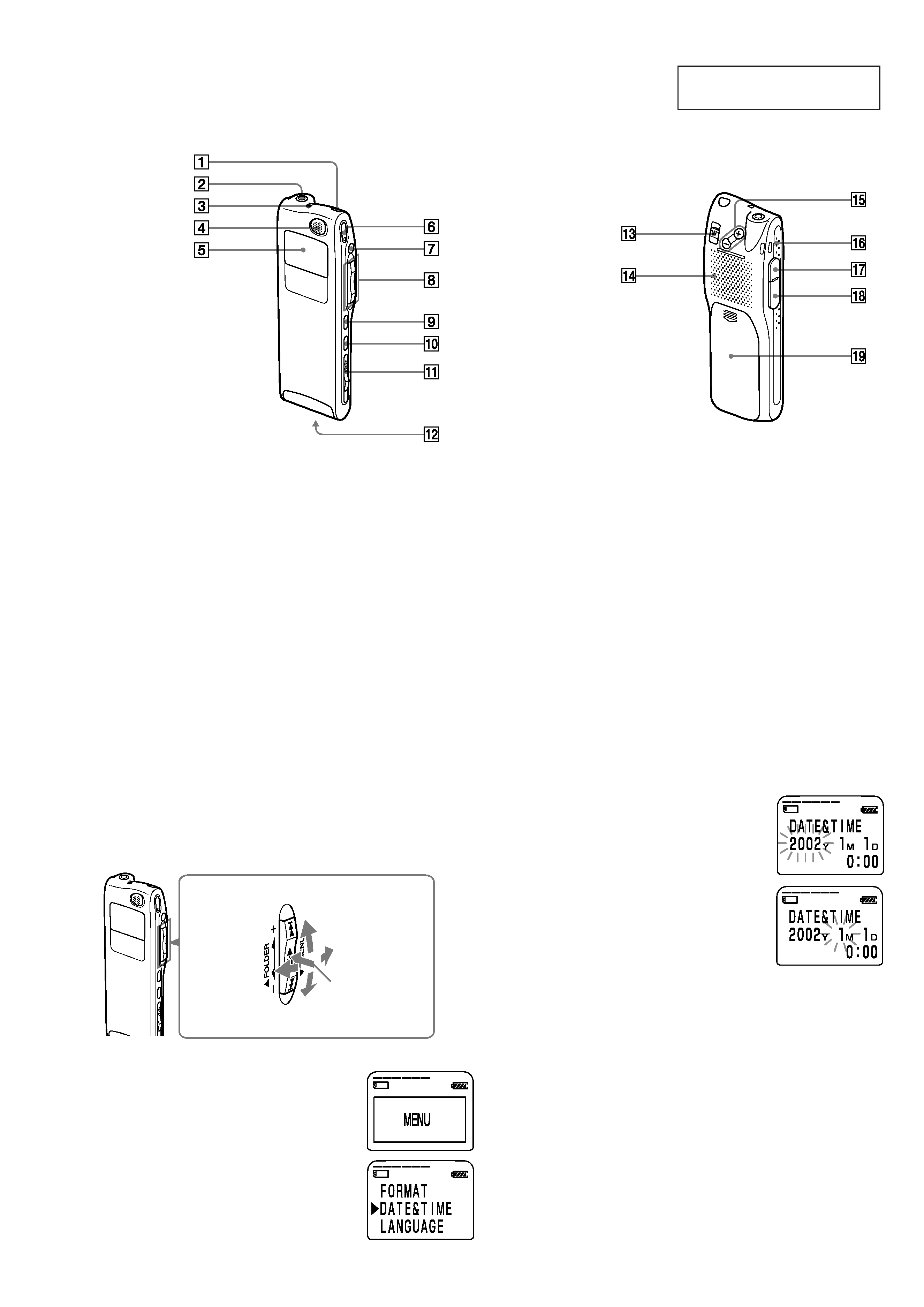
1
ERASE button (25)
2
EAR (earphone) jack (19, 22)
3
OPR (operation) indicator
(17, 22)
4
Built-in microphone (17, 31)
5
Display window (93)
6
zREC (record) /REC
PAUSE button (17, 31)
7
xSTOP button (17, 22, 27)
8
Jog lever
FOLDER/MENU/
.(review/fast backward)/
> (cue/fast forward)/
x· B (play/stop·enter) (12,
16, 21, 28, 58)
9
INDEX/BOOKMARK
button (29, 33)
0
A-B REPEAT/PRIORITY
button (30, 40)
qa
EJECT lever (15)
qs
Memory Stick slot (14)
Front
Rear
qd
HOLD switch (52)
qf
Speaker
qg
VOL (volume) +/ buttons
(22)
qh
Slit for the supplied
handstrap
qj
MIC (PLUG IN POWER)
jack (20)
qk
USB connector (70)
ql
Battery compartment (10)
Jog lever
Press the
center
Press up
Press down
Step 2: Setting the Clock
You need to set the clock to use the alarm function or record the date and
time.
Clock setting display appears when you insert battery for the first time, or
when you insert battery after the unit has been without battery for a
certain period of time. In this case, proceed from step 4.
1 Turn the jog lever toward MENU.
The menu mode will be displayed in the
display window.
2 Press the jog lever up (>) four times
to select "DATE&TIME".
3 Press the jog lever (x·B).
The date and time setting window is
displayed. The year digits will flash.
Turn
toward
MENU
Turn
toward
FOLDER
4 Set the date and time.
1
Press the jog lever up or down (>/
.)to select the digits of the year.
2
Press the jog lever (x·B).
The month digits will flash.
3
Set the month, day, and the time in
sequence, then press the jog lever
(x·B).
The menu mode will be displayed again.
5 Turn the jog lever toward MENU.
The window will return to normal display.
To display the current time
Press x STOP button during the sleep display mode (page 53).
The current time will be displayed for three seconds.
4
ICD-MS515
SECTION 2
DISASSEMBLY
Note : Follow the disassembly procedure in the numerical order given.
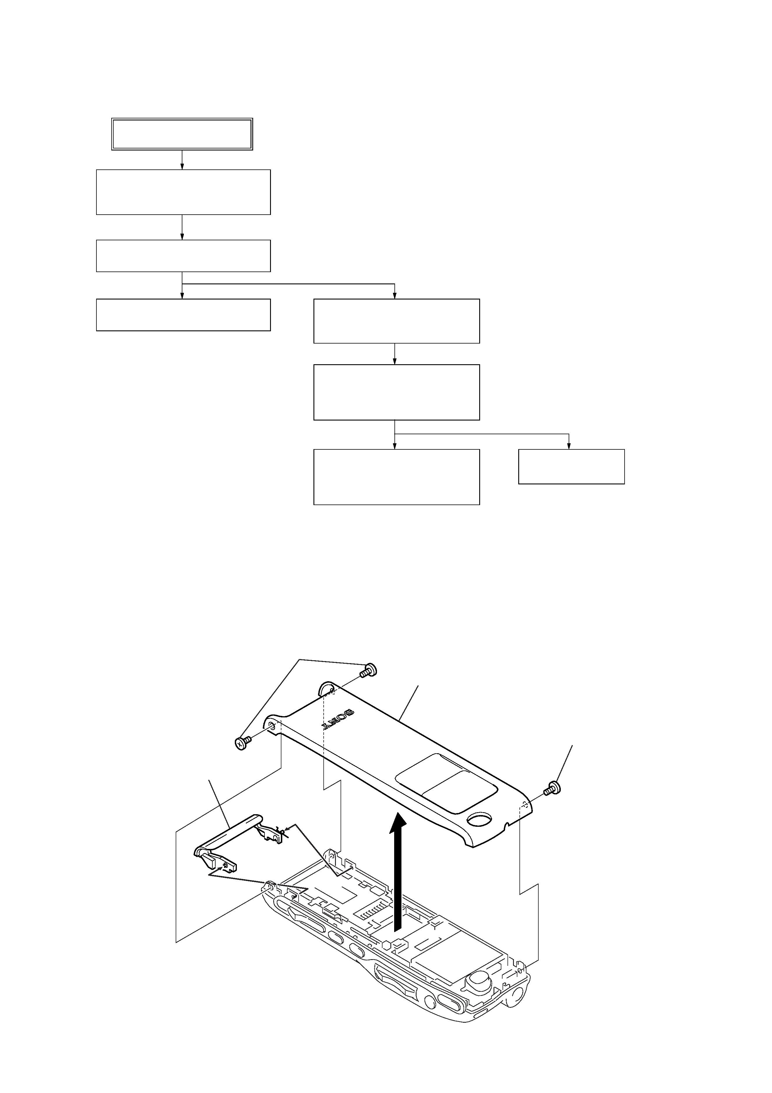
2-1.
Front Cabinet Section, Lid (M) Section
Note : Disassemble the unit in the order as shown below.
3
front cabinet section
4
lid (M), spring (Lid)
2
two screws (M 1.4)
1
screw (M 1.4)
FRONT CABINET SECTION,
LID (M) SECTION
(Page 4)
SET
LCD BLOCK ASSY
(Page 5)
LIQUID CRYSTAL INDICATOR UNIT
(Page 9)
EJECT MECHA BLOCK ASSY,
MAIN BOARD
(Page 6)
SPEAKER ASSY (SP3201),
MICROPHONE UNIT (MIC3201),
AUDIO BOARD-1
(Page 7)
SWITCH BOARD
(Page 8)
SPEAKER ASSY (SP3201),
MICROPHONE UNIT (MIC3201),
AUDIO BOARD-2
(Page 8)
5
ICD-MS515
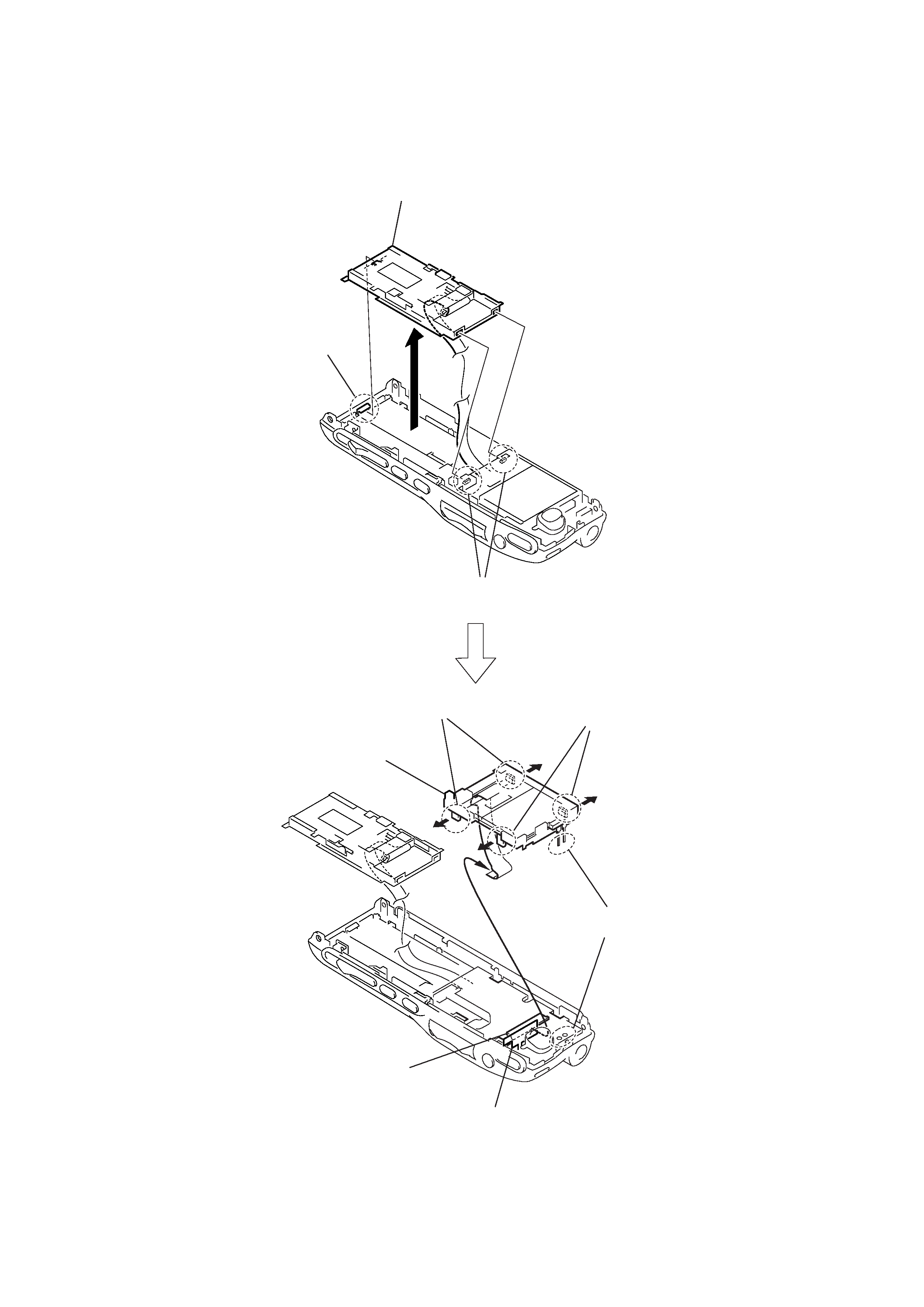
2-2.
LCD Block Assy
4
shield paper (E)
8
connector
(CN7102) (22 core)
6
two claws
7
two claws
3
eject mecha block assy
1
two claws
2
claw
9
LCD block assy
5
Remove soldering
from the two points of el element.