1
SERVICE MANUAL
US Model
Canadian Model
AEP Model
UK Model
E Model
Tourist Model
ICD-B25
IC RECORDER
Recording media
Built-in flash memory, Monaural recording
Recording time
127 minutes (SP)/339 minutes (LP)
Frequency response
SP: 250 Hz - 7,300 Hz
LP: 300 Hz - 3,500 Hz
Speaker
approx. 3.2 cm (1 5/16 in.) dia.
Power output
300 mW
Input/Output
· Earphone jack (minijack) for 16 - 300 ohms
earphone/headphones
· Microphone jack (minijack, monaural)
Plug in power
Minimum input level 0.6 mV
3 kilohms or lower impedance microphone
Playback speed control
FAST +30%, SLOW 15%
Power requirements
Two LR03 (size AAA) alkaline batteries: 3 V DC
Dimensions (w/h/d) (not incl. projecting parts and controls)
44.5
× 105.3 × 14.0 mm (1 13/16 × 4 1/4 × 9/16 in.)
Mass (incl. batteries)
68 g (2.4 oz)
Optional accessories
Electret Condenser Microphone ECM-Z60,
ECM-T115, ECM-DM5P
Connecting cord RK-G64
Your dealer may not handle some of the above listed optional accessories.
Please ask the dealer for detailed information.
Design and specifications are subject to change without notice.
SPECIFICATIONS
Ver 1.0 2002. 03
Sony Corporation
Personal Audio Company
Published by Sony Engineering Corporation
9-873-644-01
2002C0400-1
© 2002. 03

2
TABLE OF CONTENTS
1. GENERAL
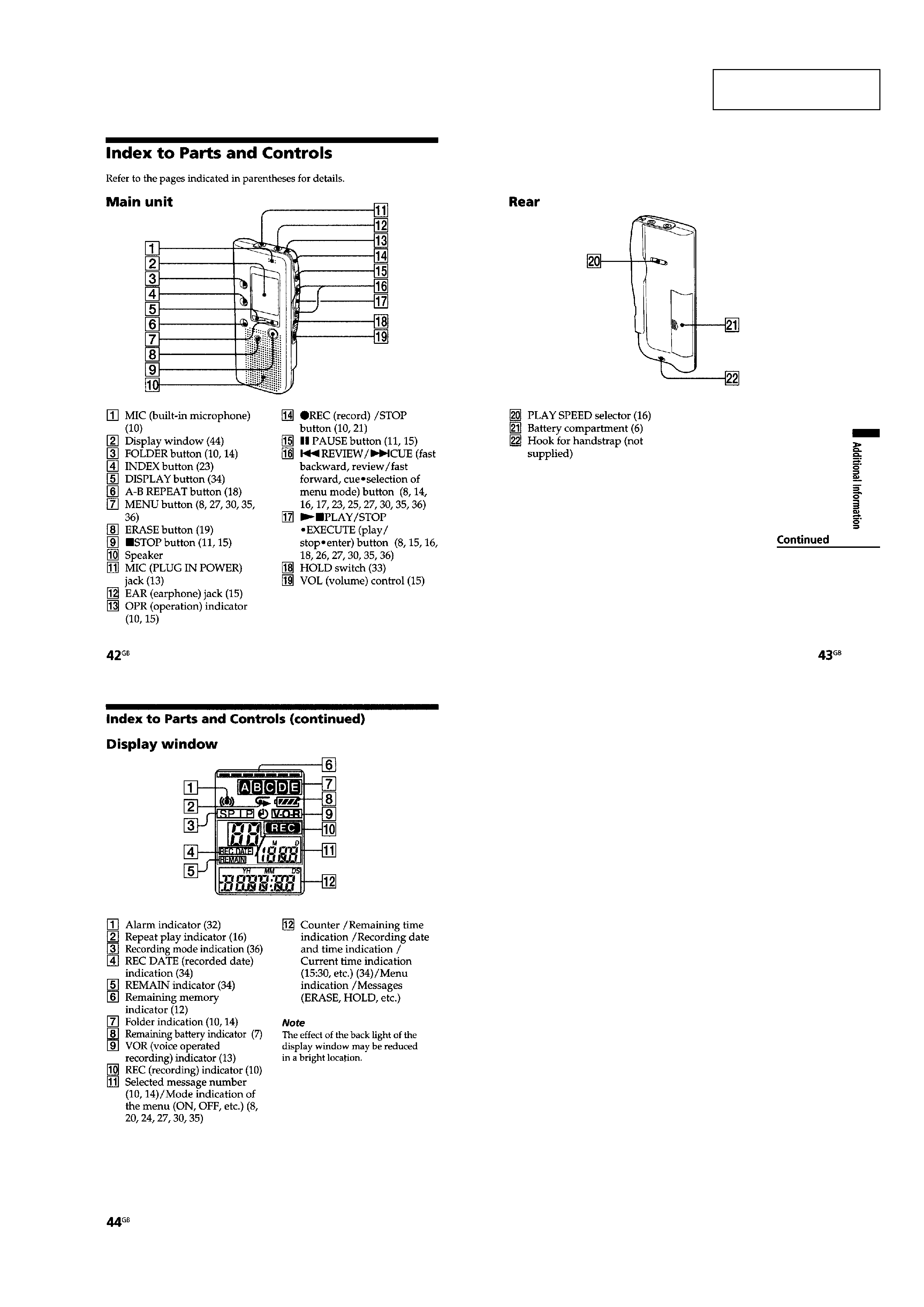
Index to Parts and Controls ..................................................... 3
2. DISASSEMBLY
2-1. Upper Lid Sub Block Assy .................................................. 4
2-2. F-sw Board .......................................................................... 4
2-3. Main Board ......................................................................... 5
3. DIAGRAMS
3-1. IC Pin Description ............................................................... 6
3-2. Block Diagram .................................................................... 8
3-3. Printed Wiring Board Main Section ............................ 10
3-4. Schematic Diagram Main Section (1/3) ...................... 12
3-5. Schematic Diagram Main Section (2/3) ...................... 13
3-6. Schematic Diagram Main Section (3/3) ...................... 14
3-7. Schematic Diagram F-sw Section ............................... 15
3-8. Printed Wiring Board F-sw Section ............................ 16
3-9. Printed Wiring Board P-sw Section ............................ 18
3-10. Schematic Diagram P-sw Section ............................... 19
4. EXPLODED VIEWS
4-1. Case Section ...................................................................... 21
4-2. Main Board Section .......................................................... 22
5. ELECTRICAL PARTS LIST ........................................ 23
SAFETY-RELATED COMPONENT WARNING!!
COMPONENTS IDENTIFIED BY MARK 0 OR DOTTED LINE
WITH MARK 0 ON THE SCHEMATIC DIAGRAMS AND IN
THE PARTS LIST ARE CRITICAL TO SAFE OPERATION.
REPLACE THESE COMPONENTS WITH SONY PARTS WHOSE
PART NUMBERS APPEAR AS SHOWN IN THIS MANUAL OR
IN SUPPLEMENTS PUBLISHED BY SONY.
Notes on Chip Component Replacement
· Never reuse a disconnected chip component.
· Notice that the minus side of a tantalum capacitor may be dam-
aged by heat.
ICD-B25
ATTENTION AU COMPOSANT AYANT RAPPORT
À LA SÉCURITÉ!!
LES COMPOSANTS IDENTIFIÉS PAR UNE MARQUE 0 SUR LES
DIAGRAMMES SCHÉMATIQUES ET LA LISTE DES PIÈCES SONT
CRITIQUES POUR LA SÉCURITÉ DE FONCTIONNEMENT. NE
REMPLACER CES COMPOSANTS QUE PAR DES PIÈCES SONY
DONT LES NUMÉROS SONT DONNÉS DANS CE MANUEL OU
DANS LES SUPPLÉMENTS PUBLIÉS PAR SONY.
· UNLEADED SOLDER
Boards requiring use of unleaded solder are printed with the lead-
free mark (LF) indicating the solder contains no lead.
(Caution: Some printed circuit boards may not come printed with
the lead free mark due to their particular size.)
: LEAD FREE MARK
Unleaded solder has the following characteristics.
·Unleaded solder melts at a temperature about 40°C higher than
ordinary solder.
Ordinary soldering irons can be used but the iron tip has to be
applied to the solder joint for a slightly longer time.
Soldering irons using a temperature regulator should be set to
about 350°C.
Caution: The printed pattern (copper foil) may peel away if
the heated tip is applied for too long, so be careful!
· Strong viscosity
Unleaded solder is more viscous (sticky, less prone to flow)
than ordinary solder so use caution not to let solder bridges
occur such as on IC pins, etc.
· Usable with ordinary solder
It is best to use only unleaded solder but unleaded solder may
also be added to ordinary solder.
3
ICD-B25
SECTION 1
GENERAL
This section is extracted
from instruction manual.
4
ICD-B25
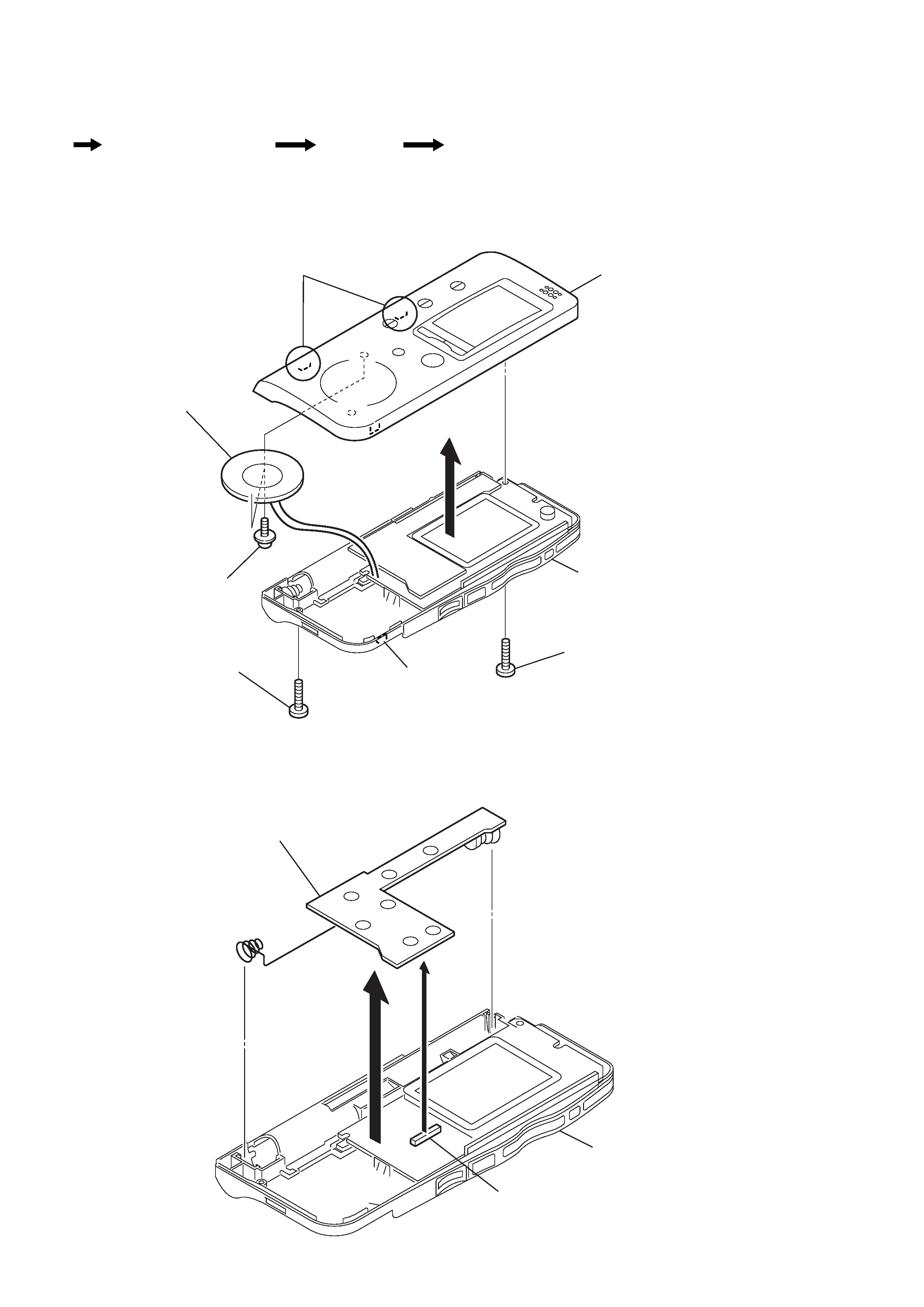
2-2. F-SW BOARD
Note : This set can be disassemble according to the following sequence.
SECTION 2
DISASSEMBLY
Note : Follow the disassembly procedure in the numerical order given.
2-1. UPPER LID SUB BLOCK ASSY
1
screw (B1.7x10)
6
upper lid sub block assy
case assy
4
claw
3
claws
5
2
screw (B1.7x7)
7
screws (B1.7x2.5)
8
speaker
1
CN703
case assy
3
F-SW board
2
Set
Upper Lid Sub Block Assy
F-SW Board
Main Board
5
ICD-B25
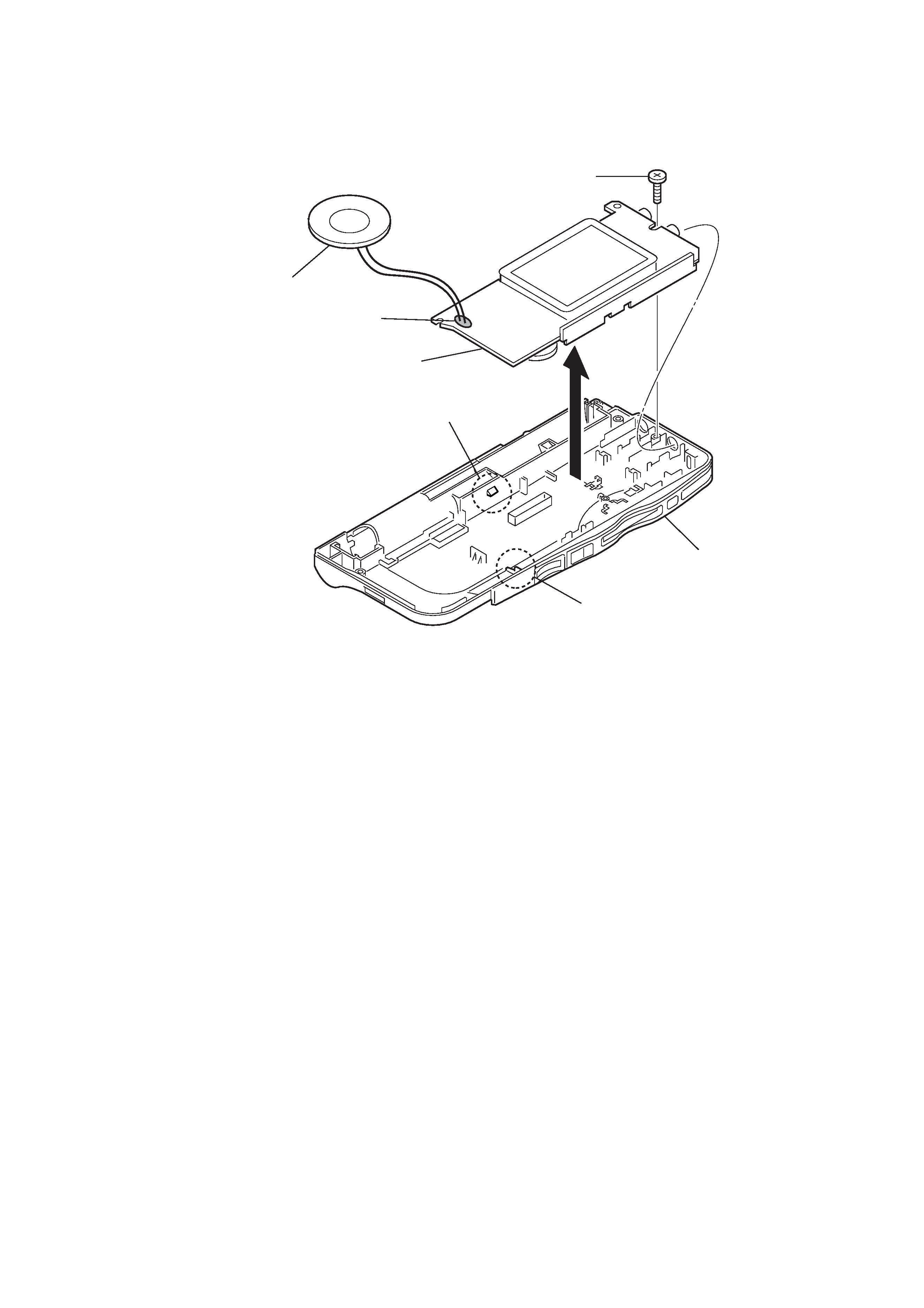
2-3. MAIN BOARD
3
screw (B1.7x10)
2
speaker
1
Removal the solders.
6
MAIN board
4
claw
5
claw
case assy