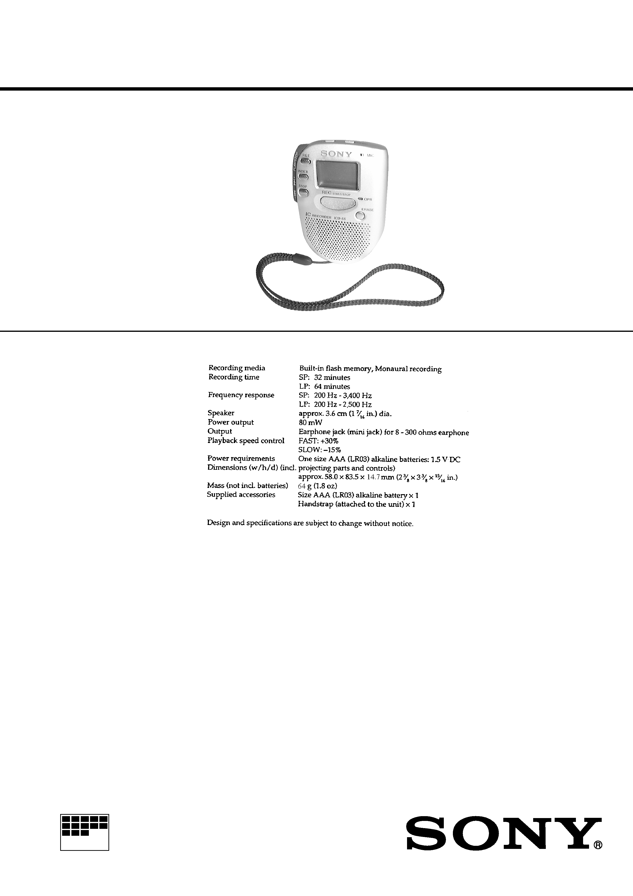
MICROFILM
SERVICE MANUAL
IC RECORDER
US Model
Canadian Model
AEP Model
E Model
Tourist Model
ICD-55
SPECIFICATIONS
Ver 1.2 2000. 05
With SUPPLEMENT-1
(9-926-902-83)

2
TABLE OF CONTENTS
1.
SERVICING NOTES ............................................... 2
2.
GENERAL ................................................................... 3
3.
DISASSEMBLY ......................................................... 4
4.
DIAGRAMS
4-1. Block Diagram ................................................................
7
4-2. Printed Wiring Board ......................................................
9
4-3. Schematic Diagram ......................................................... 11
4-4. IC Pin Function Description ........................................... 17
5.
EXPLODED VIEW ................................................... 19
6.
ELECTRICAL PARTS LIST ............................... 20
CAUTION ON REPLACING FLASH MEMORY
The BAD-BLOCK check* must be executed, when the flash
memory in this set was replaced.
The set will not operation normally, unless this check is finished.
* The BAD-BLOCK check detects an area (bad-block) in the flash
memory where data validity cannot be guaranteed, and saves this
information in the TOC-AREA so that a bad-block is not used.
BAD-BLOCK check Procedure:
1. Apply 1.5V from regulated power supply to the battery termi-
nals.
2. Once the power is supplied, the check starts and then proceeds
for approx. 20 seconds. (Be sure to keep applying the power
during the check)
3. When the check completes, the result is shown as bellows.
OK: Only the LCD back light LED (D503) turns on.
NG: Red LED blinks or turns on or green LED turns on in the
OPR LED (D504).
4. In case of OK, press the [STOP] button.
Note:
· In case of NG, check system control IC (IC701), flash memory IC and
the peripheral circuit. (Particularly, check carefully the soldering of the
flash memory)
· After finishing the BAD-BLOCK check, assemble the set, load the dry
battery, and confirm if the set operates normally.
Notes on chip component replacement
· Never reuse a disconnected chip component.
· Notice that the minus side of a tantalum capacitor may be dam-
aged by heat.
Flexible Circuit Board Repairing
· Keep the temperature of the soldering iron around 270 °C dur-
ing repairing.
· Do not touch the soldering iron on the same conductor of the
circuit board. (within 3 times)
· Be careful not to apply force on the conductor when soldering
or unsoldering.
SECTION 1
SERVICING NOTES
3
SECTION 2
GENERAL
This section is extracted from
instruction manual.
4
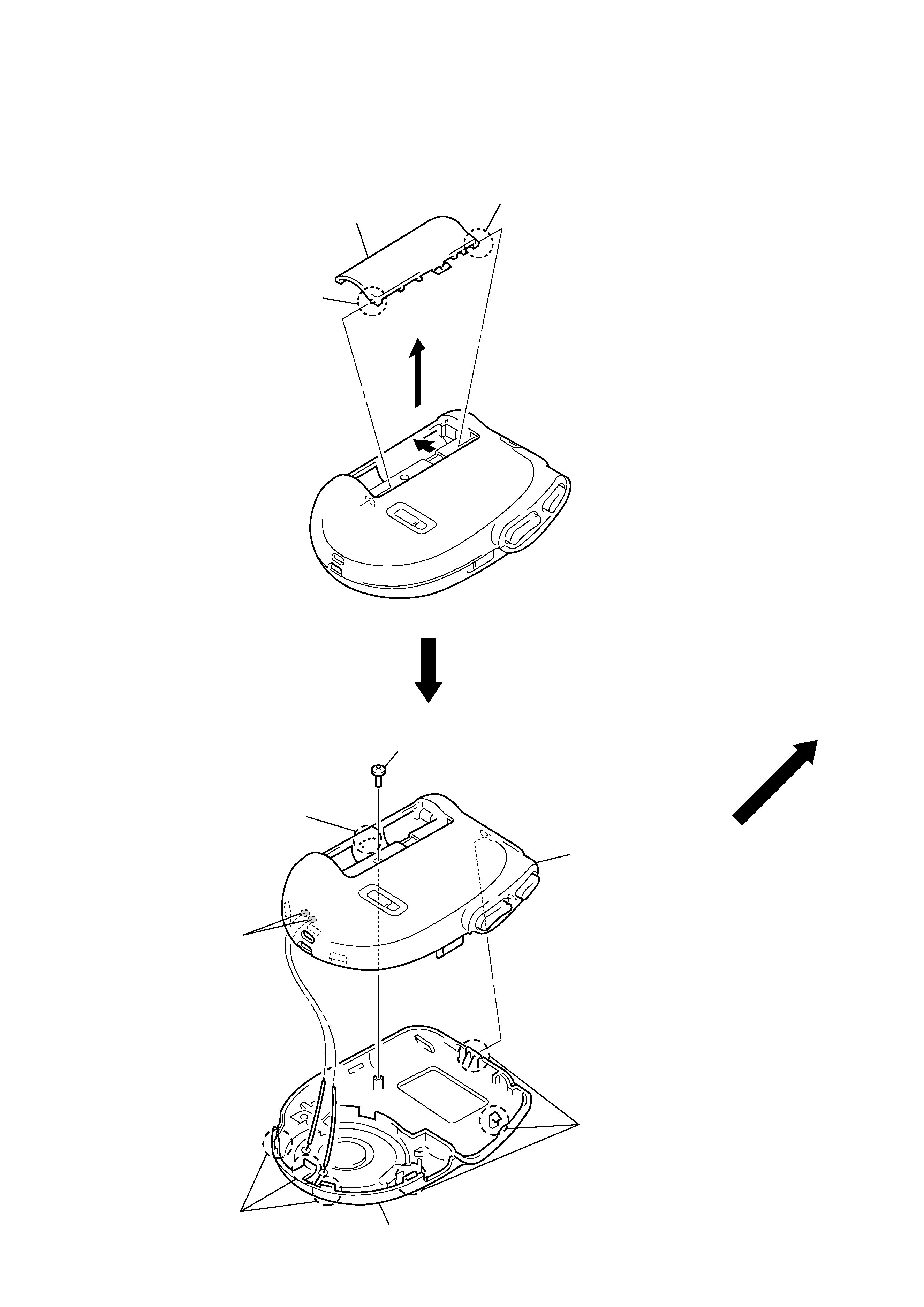
LID, BATTERY CASE
CASE (FRONT)/(REAR) SECTION
Note: Follow the disassembly procedure in the numerical order given.
SECTION 3
DISASSEMBLY
3 lid, battery case
2 boss
2 boss
1
2 claw
2 three claws
2 three claws
4 case (front) section
3 Remove the two solders
speaker lead (SP101).
1 screw (1.7
× 4.5)
5 case (rear) section
5
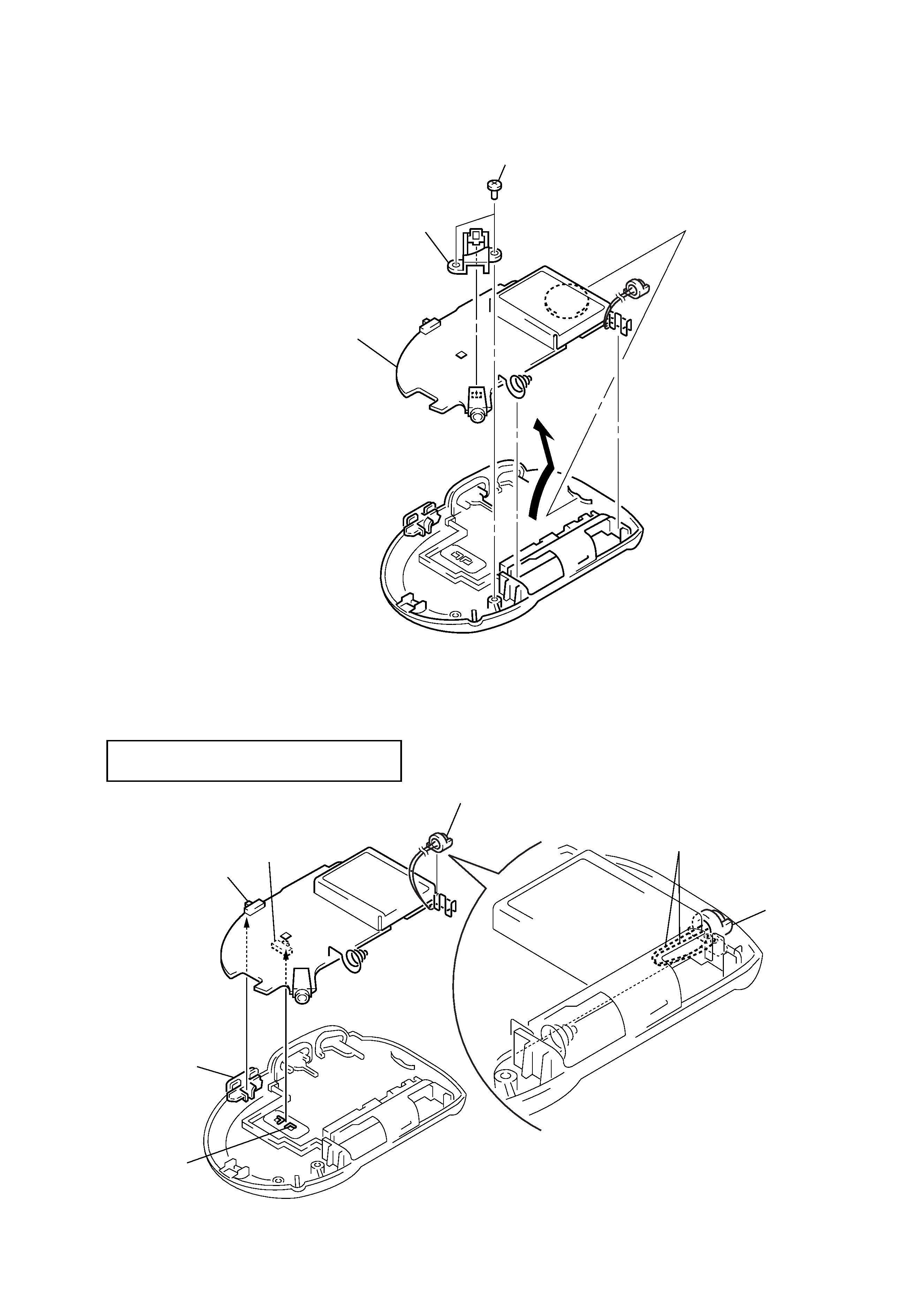
MAIN BOARD
INSTALLATION "MAIN BOARD", "MICROPHONE, ELECTRIC CONDENSER" (MIC101)
1 two screws
(M1.7
× 4)
2 bracket
(jack)
3 Remove the MAIN board to
direction of the arrow.
knob (MODE)
knob (HOLD)
S711
S712
microphone, electric condenser
(MIC101)
On installation MAIN board adjust the S711, S712
and knob (HOLD, MODE).
two leads
microphone,
electric condenser
(MIC101)
Install two leads the electric condenser microphone
(MIC101) in the figure.