1
HT-DDW830
SERVICE MANUAL
HOME THEATER SYSTEM
US Model
Canadian Model
E Model
Australian Model
Ver.1.0 2001.03
Sony Corporation
Audio Entertainment Group
General Engineering Dept.
9-873-864-11
2001C0900-1
© 2001. 3
· HT-DDW830 is composed of following models.
As for the service manual, it is issued for each component
model, then, please refer to it.
Ref. No.
Part No.
Description
Remark
ACCESSORIES & PACKING MATERIALS
********************************
1-476-552-11 COMMANDER,STANDARD (RM-U305)
1-501-374-11 ANTENNA, LOOP
1-590-480-11 CORD, CONNECTION (2M)
1-751-347-11 CORD, CONNECTION (10M)
1-769-433-61 CORD, SPEAKER (3.5M)
1-793-184-21 CONNECTOR (F TYPE ADAPTOR)
4-228-696-01 COVER, BATTERY (FOR RM-U305)
4-233-232-11 MANUAL, INSTRUCTION (ENGLISH)(US,CND,SP,AUS)
4-233-232-21 MANUAL, INSTRUCTION (FRENCH)(CND,SP)
4-233-232-31 MANUAL, INSTRUCTION (SPANISH,CNINESE)(SP)
4-233-232-41 MANUAL, INSTRUCTION (SPANISH)(MX)
4-235-731-01 INSTRUCTION (SPK)(ENGLISH,FRENCH,SPANISH,CHINESE)
4-972-322-01 FOOT (Y)(FOR SS-MSP1)
4-981-864-01 FOOT (FOR SA-WMSP1)
PARTS LIST
AMPLIFIER SECTION
STR-K502P
FRONT, CENTER AND REAR SPEAKERS
SS-MSP1
SUBWOOFER
SA-WMSP1
SPEAKER
SECTION
COMPONENT MODEL NAME
· Abbreviation
SP
: Singapore model
MX : Mexican model
AUS: Australian model

2
HT-DDW830
REVISION HISTORY
Clicking the version allows you to jump to the revised page.
Also, clicking the version at the upper right on the revised page allows you to jump to the next revised page.
Ver.
Date
Description of Revision
1.0
2001.03
New
STR-DE575/K502/K502P
US Model
STR-DE575/K502/K502P
Canadian Model
STR-DE575/K502P
E Model
Australian Model
STR-K502P
SERVICE MANUAL
FM STEREO FM-AM RECEIVER
Sony Corporation
Home Audio Company
Published by Sony Engineering Corporation
9-873-862-12
2002G1600-1
© 2002.07
-- Continued on next page --
SPECIFICATIONS
Ver 1.1 2002. 07
Dolby Laboratories Licensing Corporation.
"DOLBY" the double-D symbol ; "AC-3" and "PRO LOGIC"
are trademarks of Dolby Laboratories Licensing Corporation.
AUDIO POWER
SPECIFICATIONS
POWER OUTPUT AND
TOTAL HARMONIC
DISTORTION:
With 8 ohm loads, both
channels driven, from 20 -
20,000 Hz; rated 100 watts
per channel minimum RMS
power, with no more than
0.09% total harmonic
distortion from 250
milliwatts to rated output
(USA model only).
Amplifier section
(8 ohms 20 Hz - 20 kHz,
THD 0.09%)
100 W + 100 W
(8 ohms at 1 kHz, THD
0.7%)
Front1): 100 W/ch
Center1): 100 W
Surround1): 100 W/ch
1) Depending on the sound field settings and
sources, there may be no sound output.
MULTI CH IN, CD,
MD/TAPE, DVD/
LD, TV/SAT,
VIDEO*, AUX:
10 Hz - 50 kHz +0.5/
2 dB (with sound
field and equalizer
bypassed)
MULTI CH IN, CD,
DVD/LD, MD/
TAPE, TV/SAT,
VIDEO*, AUX:
Sensitivity: 250 mV
Impedance: 50
kilohms
S/Na): 96 dB (A, 250
mVb))
a) Input short.
b) Weighted network, input level.
DVD/LD (coaxial):
Sensitivity:
Impedance: 75 ohms
S/N: 100 dB (A, 20
kHz LPF)
(Optical):
Sensitivity:
Impedance:
S/N: 100 dB (A, 20
kHz LPF)
MD/TAPE, (OUT);
VIDEO*,
(AUDIO OUT):
Voltage: 250 mV,
Impedance: 10
kilohms
SUB WOOFER:
Voltage: 2 V
Impedance: 1
kilohms
PHONES:
Accepts low- and
high-impedance
headphones
±6 dB
DVD/LD, TV/SAT
48 kHz (TV/SAT, MD/
TAPE OPTICAL IN)
96 kHz (DVD/LD
OPTICAL IN,
COAXIAL IN)
Sampling Frequency
EQ
Outputs
Frequency response
Inputs (Analog)
Inputs (Digital)
Reference Power Output
Rated Power Output at Stereo mode
Photo : STR-DE575

2
STR-DE575/K502/K502P
0.5 % (50 mV/m, 400
kHz)
At 9 kHz: 35 dB
At 10 kHz: 40 dB
c) You can change the AM tuning interval to 9
kHz. After tuning in any AM station, turn
off the receiver. Hold down the TUNING +
button and press the ?/1 button. All preset
stations will be erased when you change the
tuning interval. To reset the scale to 10 kHz,
repeat the procedure.
Video section
Video: 1 Vp-p 75 ohms
S-video***:
Y: 1 Vp-p 75 ohms
C: 0.286 Vp-p 75 ohms
Video: 1 Vp-p 75 ohms
S-video***:
Y: 1 Vp-p 75 ohms
C: 0.286 Vp-p 75 ohms
General
Tuner section:
PLL quartz-locked
digital synthesizer
system
Preamplifier section:
Low-noise NF type
equalizer
Power amplifier
section:
Pure-complementary
SEPP
FM tuner section
87.5 - 108.0 MHz
75 ohms, unbalanced
10.7 MHz
Mono: 18.3 dBf,
2.2
µV/75 ohms
Stereo: 38.3 dBf
22.5
µV/75 ohms
11.2 dBf, 1
µV/75 ohms
Mono: 76 dB
Stereo: 70 dB
Mono: 0.3%
Stereo: 0.5%
45 dB at 1 kHz
30 Hz - 15 kHz +0.5/2
dB
60 dB at 400 kHz
AM tuner section
With 10-kHz tuning
scale:
530 - 1710 kHzc)
With 9-kHz tuning
scale:
531 - 1710 kHzc)
Loop antenna
450 kHz
50 dB/m (at 1,000 kHz
or 999 kHz)
54 dB (at 50 mV/m)
120 V AC, 60 Hz
Models of area code U:
220W
In standby condition:
1 W
Models of area code CA:
315 VA
In standby condition:
1 W
1 switched, total
120 W/1A Max
430
× 308.5 × 157.5 mm
(14.5
× 10.4 × 5.3 in.)
including projecting
parts and controls
7.5 kg (16 lbs. 9 oz.)
7.4 kg (16 lbs. 6 oz.)
Design and specifications are subject
to change without notice.
· FM wire antenna (1)
· AM loop antenna (1)
·
· STR-DE575 only
· STR-K502 only
· Model of area code U only
- Remote commander RM-U305 (remote) (1)
· Model of area code CA only
- Remote commander RM-PP505 (remote) (1)
· Remote commander RM-U305 (remote) (1)
R6 (size-AA) batteries (2)
*** STR-DE575 only
Tuning range
Antenna terminals
Intermediate frequency
Sensitivity
Usable sensitivity
S/N
Harmonic distortion at 1 kHz
Separation
Frequency response
Selectivity
Tuning range
Antenna
Intermediate frequency
Usable sensitivity
S/N
Harmonic distortion
Selectivity
Inputs
Outputs
System
Supplied accessories
Mass (Approx.)
Dimensions
AC outlets
Power consumption
Power requirements
3
STR-DE575/K502/K502P
SAFETY-RELATED COMPONENT WARNING!!
COMPONENTS IDENTIFIED BY MARK 0 OR DOTTED LINE WITH
MARK 0 ON THE SCHEMATIC DIAGRAMS AND IN THE PARTS
LIST ARE CRITICAL TO SAFE OPERATION. REPLACE THESE
COMPONENTS WITH SONY PARTS WHOSE PART NUMBERS
APPEAR AS SHOWN IN THIS MANUAL OR IN SUPPLEMENTS
PUBLISHED BY SONY.
After correcting the original service problem, perform the
following safety checks before releasing the set to the customer:
Check the antenna terminals, metal trim, "metallized" knobs, screws,
and all other exposed metal parts for AC leakage. Check leakage as
described below.
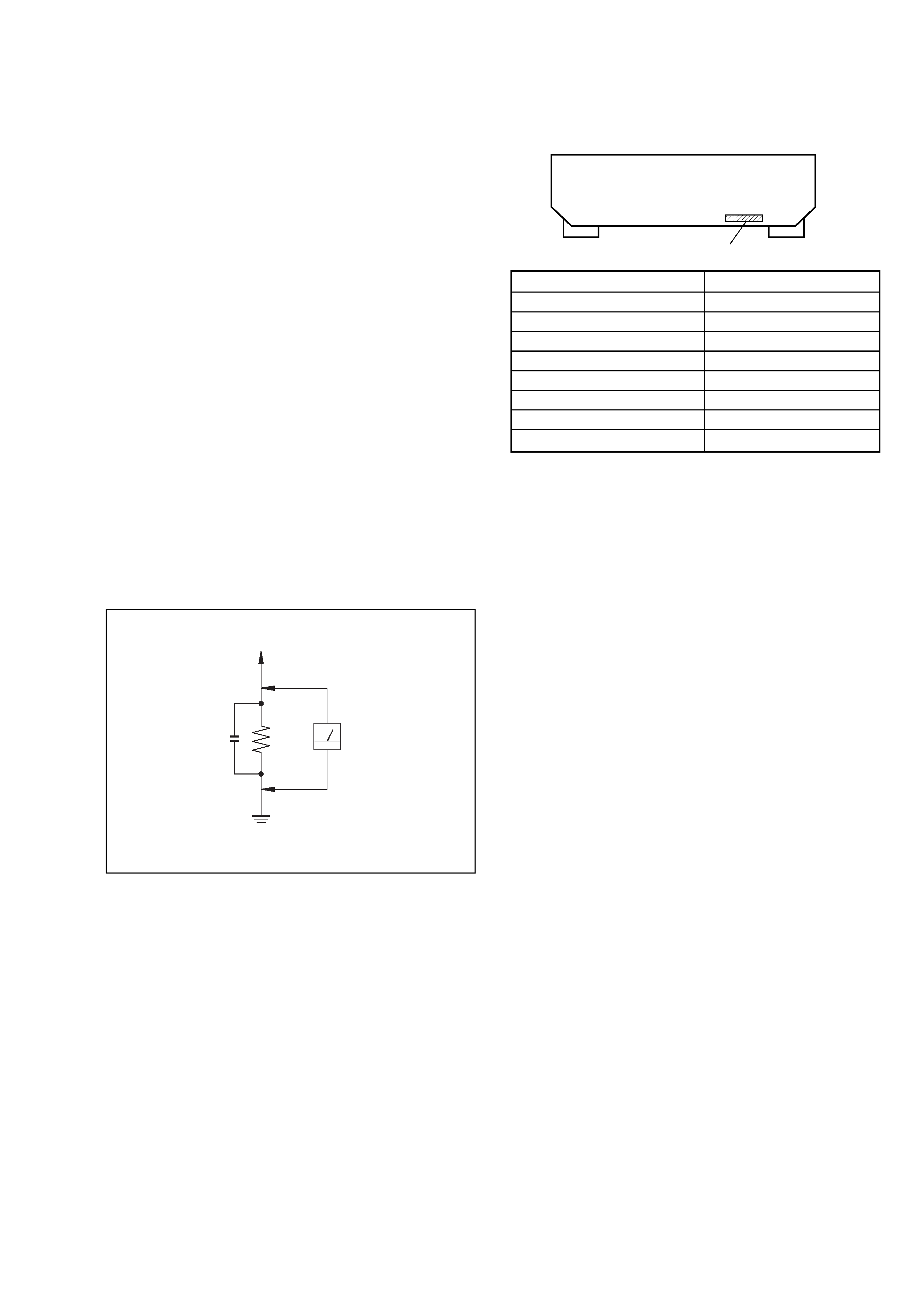
LEAKAGE
The AC leakage from any exposed metal part to earth ground
and from all exposed metal parts to any exposed metal part having
a return to chassis, must not exceed 0.5 mA (500 microamperes).
Leakage current can be measured by any one of three methods.
1.
A commercial leakage tester, such as the Simpson 229 or RCA
WT-540A. Follow the manufacturers' instructions to use these
instruments.
2.
A battery-operated AC milliammeter. The Data Precision 245
digital multimeter is suitable for this job.
3.
Measuring the voltage drop across a resistor by means of a
VOM or battery-operated AC voltmeter. The "limit" indication
is 0.75 V, so analog meters must have an accurate low-voltage
scale. The Simpson 250 and Sanwa SH-63Trd are examples of
a passive VOM that is suitable. Nearly all battery operated
digital multimeters that have a 2V AC range are suitable. (See
Fig. A)
SAFETY CHECK-OUT
Parts No.
MODEL IDENTIFICATION
-- BACK PANEL --
ATTENTION AU COMPOSANT AYANT RAPPORT
À LA SÉCURITÉ!
LES COMPOSANTS IDENTIFÉS PAR UNE MARQUE 0 SUR LES
DIAGRAMMES SCHÉMATIQUES ET LA LISTE DES PIÈCES SONT
CRITIQUES POUR LA SÉCURITÉ DE FONCTIONNEMENT. NE
REMPLACER CES COMPOSANTS QUE PAR DES PIÈSES SONY
DONT LES NUMÉROS SONT DONNÉS DANS CE MANUEL OU
DANS LES SUPPÉMENTS PUBLIÉS PAR SONY.
PARTS No.
4-232-240-0s
4-232-240-1s
4-232-240-3s
4-232-240-4s
4-232-240-5s
4-232-240-6s
4-232-240-7s
4-232-240-8s
MODEL
DE575 : US
DE575 : Canadian
K502P : US
K502P : Canadian
K502P : Australian
K502P : Singapore
K502P : Mexican
K502
: US
To Exposed Metal
Parts on Set
0.15
µF
1.5 k
AC
Voltmeter
(0.75 V)
Earth Ground
Fig. A. Using an AC voltmeter to check AC leakage.