CHASSIS
SERVICE MANUAL
SPECIFICATIONS
MICROFILM
HIT
US Model
Canadian Model
Chassis No. SCC-L28B-A
TRINITRON® COLOR GRAPHIC DISPLAY
HMD-V200
CRT
0.24 mm aperture grille pitch
17 inches measured diagonally
90-degree deflection
FD Trinitron
Viewable image size
Approx. 327
× 243 mm (w/h)
(12 7/8
× 9 5/8 inches)
16.0" viewing image
Resolution
Horizontal: Max. 1280 dots
Vertical: Max. 1024 lines
Standard image area
Approx. 312
× 234 mm (w/h)
(12 3/8
× 9 1/4 inches)
Deflection frequency*
Horizontal: 30 to 70 kHz
Vertical: 48 to 120 Hz
Speaker
1W + 1W (max.)
Headphones output
Stereo minijack, impedance 8
Audio input
3.5 mm stereo miniplug, input
level 0.7 Vrms typical
AC input voltage/current
100 to 120 V, 50 60 Hz, 1.8
1.5 A
Power consumption
Max. 150 W
Dimensions
Approx. 411.5
× 390 × 474 mm
(w/h/d) (16 1/4
× 15 3/8 × 18 3/4
inches) when tilted at a 25
°
angle
Mass
Approx. 22 kg (48 lb 8 oz)
Plug and Play
DDC1/DDC2B
Supplied accessories
Power cord (1)
Windows Monitor Information
Disk (1)
Warranty card (1)
Notes on cleaning the screen's
surface (1)
This instruction manual (1)
* Recommended horizontal and vertical timing condition
· Horizontal sync width duty should be more than 4.8%
of total horizontal time or 0.8 µsec, whichever is larger.
· Horizontal blanking width should be more than 2.5
µsec.
· Vertical blanking width should be more than 450 µsec.
Design and specifications are subject to change without
notice.
Preset mode timing table
No. Resolution
(dots
× lines)
Horizontal
Frequency
Vertical
Frequency
Graphics
Mode
1
640
× 400
31.5 kHz
70 Hz
MCGA
2
640
× 480
31.5 kHz
60 Hz
VGA
3
640
× 480
43.3 kHz
85 Hz
VESA
4
800
× 600
37.9 kHz
60 Hz
VESA
5
800
× 600
46.9 kHz
75 Hz
VESA
6
1024
× 768
60.0 kHz
75 Hz
VESA
7
1024
× 768
68.7 kHz
85 Hz
VESA
8
1152
× 864
54.9 kHz
60 Hz
ATI
9
1280
× 1024
64.0 kHz
59 Hz
VESA
HMD-V200
2
DIAGNOSIS
Failure
Power LED
HV Failure
Blink Amber (On 0.5 sec, Off 0.5 sec)
H Stop or V Stop (Included S-Cap),
Thermal Failure
Blink Amber (On 1.5 sec, Off 0.5 sec)
ABL Failure
Blink Amber (On 0.5 sec, Off 1.5 sec)
Aging/Over Ride
Blink Green (On 0.5 sec, Off 0.5 sec) .... Blink Red (On 0.5 sec, Off 0.5 sec)
TIMING SPECIFICATION
PRIMARY MODE
PRIMARY
MODE AT PRODUCTION
MODE 1
MODE 2
MODE 3
MODE 4
MODE 5
MODE 6
MODE 7
MODE 8
MODE 9
RESOLUTION
640 X 480
800 X 600
800 X 600
1024 X 768
1024 X 768
1280 X 1024
640 X 400
640 X 480
1152 X 864
CLOCK
36.000 MHZ
40.000 MHZ
49.500 MHZ
78.750 MHZ
94.500 MHZ
108.000 MHZ
25.175 MHZ
25.175 MHZ
80.000 MHZ
-- HORIZONTAL --
H-FREQ
43.269 kHz
37.879 kHz
46.875 kHz
60.023 kHz
68.677 kHz
63.981 kHz
31.469 kHz
31.469 kHz
54.945 kHz
usec
usec
usec
usec
usec
usec
usec
usec
usec
H. TOTAL
23.111
26.400
21.333
16.660
14.561
15.630
31.778
31.778
18.200
H. BLK
5.333
6.400
5.172
3.657
3.725
3.778
6.356
6.356
3.800
H. FP
1.556
1.000
0.323
0.203
0.508
0.444
0.636
0.636
0.800
H. SYNC
1.556
3.200
1.616
1.219
1.016
1.037
3.813
3.813
1.400
H. BP
2.222
2.200
3.232
2.235
2.201
2.296
1.907
1.907
1.600
H. ACTIV
17.778
20.00
16.162
13.003
10.836
11.852
25.422
25.422
14.400
-- VERTICAL --
V. FREQ(HZ)
85.008 Hz
60.317 Hz
75.000 Hz
75.029 Hz
84.997 Hz
60.020 Hz
70.086 Hz
59.940 Hz
59.984 Hz
lines
lines
lines
lines
lines
lines
lines
lines
lines
V. TOTAL
509
628
625
800
808
1066
449
525
916
V. BLK
29
28
25
32
40
42
49
45
52
V. FP
111
111
12
10
6
V. SYNC
3
4
3
33322
5
V. BP
25
23
21
28
36
38
35
33
41
V. ACTIV
480
600
600
768
768
1024
400
480
864
-- SYNC --
INT(G)
NO
NO
NO
NO
NO
NO
NO
NO
NO
EXT(H/V)/POLARITY
YES N/N
YES P/P
YES P/P
YES P/P
YES P/P
YES P/P
YES N/P
YES N/N
YES P/P
EXT(CS)/POLARITY
NO
NO
NO
NO
NO
NO
NO
NO
NO
INT/NON INT
NON INT
NON INT
NON INT
NON INT
NON INT
NON INT
NON INT
NON INT
NON INT
99.4.20 VER.
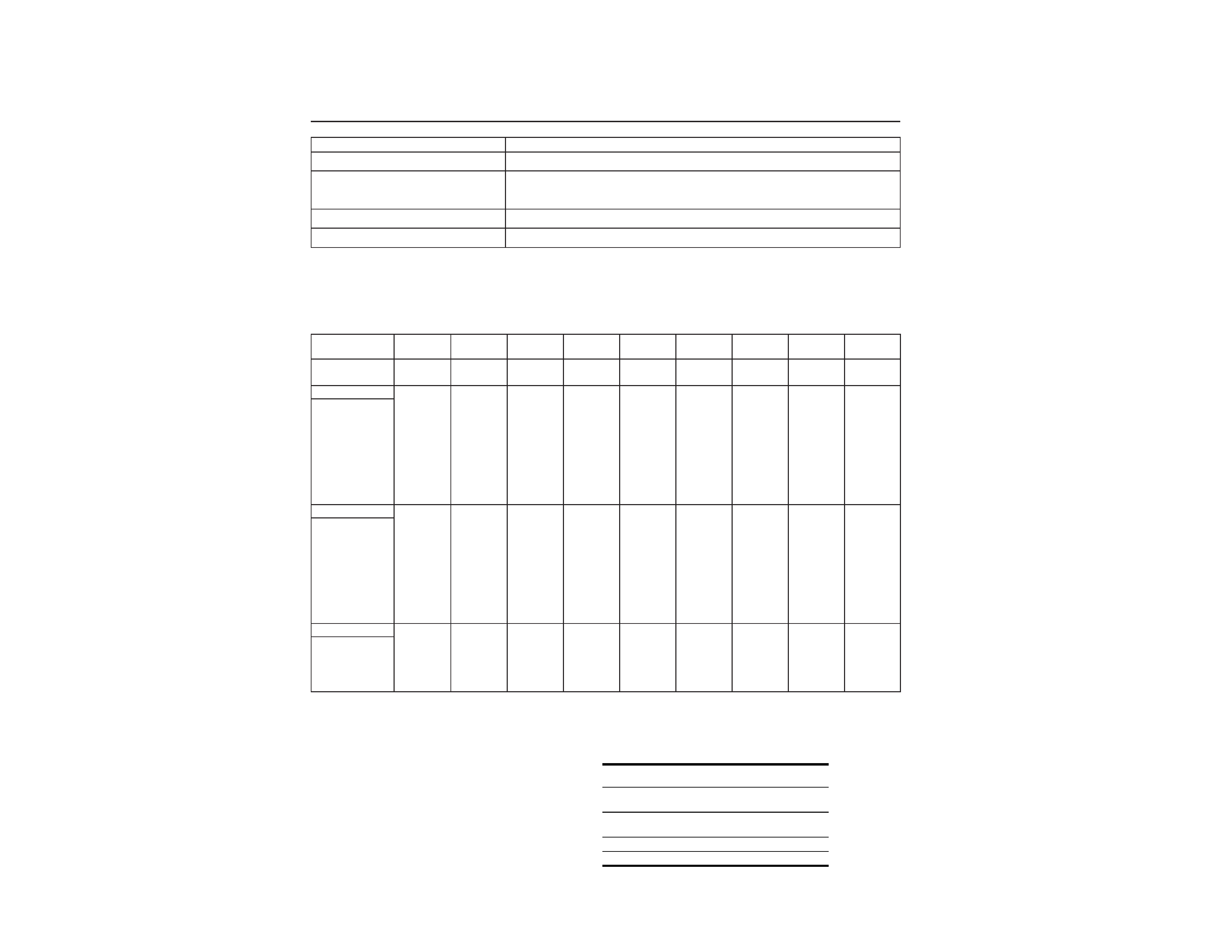
Power saving function
This monitor meets the power-saving guidelines set by
VESA,
ENERGY STAR, and NUTEK. If the monitor is
connected to a computer or graphics board that is DPMS
(Display Power Management Signaling) compliant, the
monitor will automatically reduce power consumption in
three stages as shown right.
When your computer enters a power saving mode, the input signal
is cut and NO INPUT SIGNAL appears on the screen. After a few
seconds, the monitor also enters the power saving mode.
* Even if you turn the power off, the
1 (power) indicator remains
lit for a few seconds.
Power mode
Power
consumption*
1 (power)
indicator
normal
operation
150 W
green
1 suspend
15 W
green and orange
alternate
2 active off
2 W
orange
power off*
0 W
off
HMD-V200
3
LEAKAGE TEST
The AC leakage from any exposed metal part to earth ground
and from all exposed metal parts to any exposed metal part hav-
ing a return to chassis, must not exceed 0.5 mA (500
microampers).
Leakage current can be measured by any one of three methods.
1. A commercial leakage tester, such as the Simpson 229 or
RCA WT-540A. Follow the manufacturers' instructions to
use these instruments.
2. A battery-operated AC milliammeter. The Data Precision
245 digital multimeter is suitable for this job.
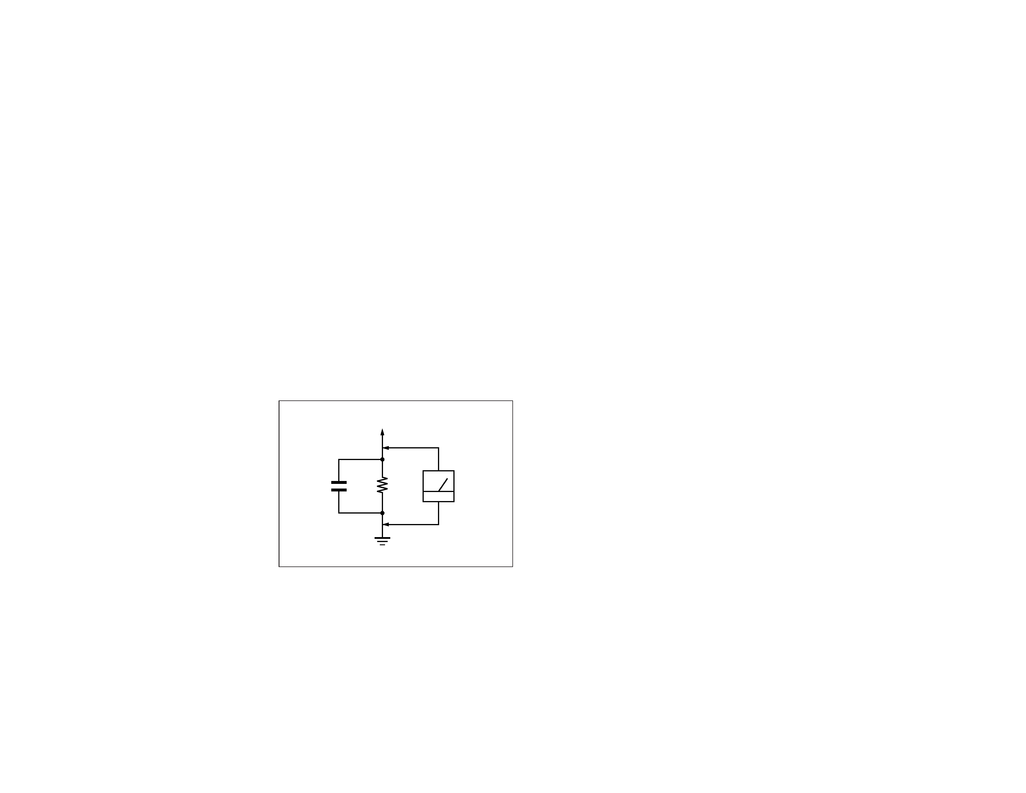
3. Measuring the voltage drop across a resistor by means of a
VOM or battery-operated AC voltmeter. The "limit" indica-
tion is 0.75 V, so analog meters must have an accurate low-
voltage scale. The Simpson 250 and Sanwa SH-63Trd are
examples of a passive VOMs that are suitable. Nearly all
battery operated digital multimeters that have a 2 V AC
range are suitable. (See Fig. A)
WARNING!!
NEVER TURN ON THE POWER IN A CONDITION IN
WHICH THE DEGAUSS COIL HAS BEEN REMOVED.
SAFETY-RELATED COMPONENT WARNING!!
COMPONENTS IDENTIFIED BY SHADING AND MARK
¡ ON THE SCHEMATIC DIAGRAMS, EXPLODED
VIEWS AND IN THE PARTS LIST ARE CRITICAL FOR
SAFE OPERATION. REPLACE THESE COMPONENTS
WITH SONY PARTS WHOSE PART NUMBERS AP-
PEAR AS SHOWN IN THIS MANUAL OR IN SUPPLE-
MENTS PUBLISHED BY SONY. CIRCUIT ADJUST-
MENTS THAT ARE CRITICAL FOR SAFE OPERATION
ARE IDENTIFIED IN THIS MANUAL. FOLLOW THESE
PROCEDURES WHENEVER CRITICAL COMPONENTS
ARE REPLACED OR IMPROPER OPERATION IS SUS-
PECTED.
AVERTISSEMENT!!
NE JAMAIS METTRE SOUS TENSION QUAND LA
BOBINE DE DEMAGNETISATION EST ENLEVÉE.
ATTENTION AUX COMPOSANTS RELATIFS À LA
SÉCURITÉ!!
LES COMPOSANTS IDENTIFIÉS PAR UNE TRAME ET
UNE MARQUE
¡ SONT CRITIQUES POUR LA SÉCURITÉ.
NE LES REMPLACER QUE PAR UNE PIÈCE PORTANT LE
NUMÉRO SPECIFIÉ. LES RÉGLAGES DE CIRCUIT DONT
L'IMPORTANCE EST CRITIQUE POUR LA SÉCURITÉ DU
FONCTIONNEMENT SONT IDENTIFIÉS DANS LE
PRÉSENT MANUEL. SUIVRE CES PROCÉDURES LORS
DE CHAQUE REMPLACEMENT DE COMPOSANTS CRI-
TIQUES, OU LORSQU'UN MAUVAIS FONCTIONNEMENT
EST SUSPECTÉ.
After correcting the original service problem, perform the fol-
lowing safety checks before releasing the set to the customer:
1. Check the area of your repair for unsoldered or poorly-sol-
dered connections. Check the entire board surface for solder
splashes and bridges.
2. Check the interboard wiring to ensure that no wires are
"pinched" or contact high-wattage resistors.
3. Check that all control knobs, shields, covers, ground straps,
and mounting hardware have been replaced. Be absolutely
certain that you have replaced all the insulators.
4. Look for unauthorized replacement parts, particularly tran-
sistors, that were installed during a previous repair. Point
them out to the customer and recommend their replacement.
5. Look for parts which, though functioning, show obvious
signs of deterioration. Point them out to the customer and
recommend their replacement.
6. Check the line cords for cracks and abrasion. Recommend
the replacement of any such line cord to the customer.
7. Check the B+ and HV to see if they are specified values.
Make sure your instruments are accurate; be suspicious of
your HV meter if sets always have low HV.
8. Check the antenna terminals, metal trim, "metallized"
knobs, screws, and all other exposed metal parts for AC
Leakage. Check leakage as described below.
Fig. A. Using an AC voltmeter to check AC leakage.
SAFETY CHECK-OUT
1.5 k
0.15
µF
AC
Voltmeter
(0.75 V)
To Exposed Metal
Parts on Set
Earth Ground

HMD-V200
4
TABLE OF CONTENTS
Section
Title
Page
1. GENERAL .................................................................. 1-1
2. DISASSEMBLY
2-1.
Cabinet Removal ................................................. 2-1
2-2.
A Board Removal ................................................ 2-1
2-3.
D Board Removal ................................................. 2-2
2-4.
G Board Removal ................................................. 2-2
2-5.
Service Position .................................................... 2-2
2-6.
Bezel Assembly, J, H and M Boards Removal ... 2-3
2-7.
Picture Tube Removal .......................................... 2-4
2-8.
Harnes Location ................................................... 2-5
3. SAFETY RELATED ADJUSTMENT ............. 3-1
4. ADJUSTMENTS ...................................................... 4-1
5. DIAGRAMS
5-1.
Block Diagrams ................................................... 5-1
5-2.
Frame Schematic Diagram .................................. 5-7
5-3.
Circuit Boards Location ...................................... 5-9
5-4.
Schematic Diagrams and Printed Wiring Boards ...... 5-10
(1) Schematic Diagram of A Board .......................... 5-11
(2) Schematic Diagram of D Board .......................... 5-19
(3) Schematic Diagrams of C, H, J and
M Boards ............................................................... 5-23
(4) Schematic Diagram of G Board .......................... 5-27
5-5. Semiconductors ................................................... 5-33
6. EXPLODED VIEWS
6-1.
Chassis ................................................................. 6-1
6-2.
Picture Tube .......................................................... 6-2
6-3.
Packing Materials ................................................ 6-3
7. ELECTRICAL PARTS LIST ............................ 7-1
1-1
SECTION 1
GENERAL
The operating instructions mentioned here are partial abstracts
from the Operating Instruction Manual. The page numbers of
the Operating Instruction Manual remein as in the manual.
4
Precautions
Warning on power connections
· Use the supplied power cord. If you use a different power cord,
be sure that it is compatible with your local power supply.
For the customers in the U.S.A.
If you do not use the appropriate cord, this monitor will not
conform to mandatory FCC standards.
· Before disconnecting the power cord, wait at least 30 seconds
after turning off the power to allow the static electricity on the
screen's surface to discharge.
· After the power is turned on, the screen is demagnetized
(degaussed) for about 3 seconds. This generates a strong
magnetic field around the screen which may affect data stored
on magnetic tapes and disks placed near the monitor. Be sure to
keep magnetic recording equipment, tapes, and disks away
from the monitor.
Installation
Do not install the monitor in the following places:
· on surfaces (rugs, blankets, etc.) or near materials (curtains,
draperies, etc.) that may block the ventilation holes
· near heat sources such as radiators or air ducts, or in a place
subject to direct sunlight
· in a place subject to severe temperature changes
· in a place subject to mechanical vibration or shock
· on an unstable surface
· near equipment which generates magnetism, such as a
transformer or high voltage power lines
· near or on an electrically charged metal surface
Maintenance
· Clean the screen with a soft cloth. If you use a glass cleaning
liquid, do not use any type of cleaner containing an anti-static
solution or similar additive as this may scratch the screen's
coating.
· Do not rub, touch, or tap the surface of the screen with sharp or
abrasive items such as a ballpoint pen or screwdriver. This type
of contact may result in a scratched picture tube.
· Clean the cabinet, panel and controls with a soft cloth lightly
moistened with a mild detergent solution. Do not use any type
of abrasive pad, scouring powder or solvent, such as alcohol or
benzene.
Transportation
When you transport this monitor for repair or shipment, use the
original carton and packing materials.
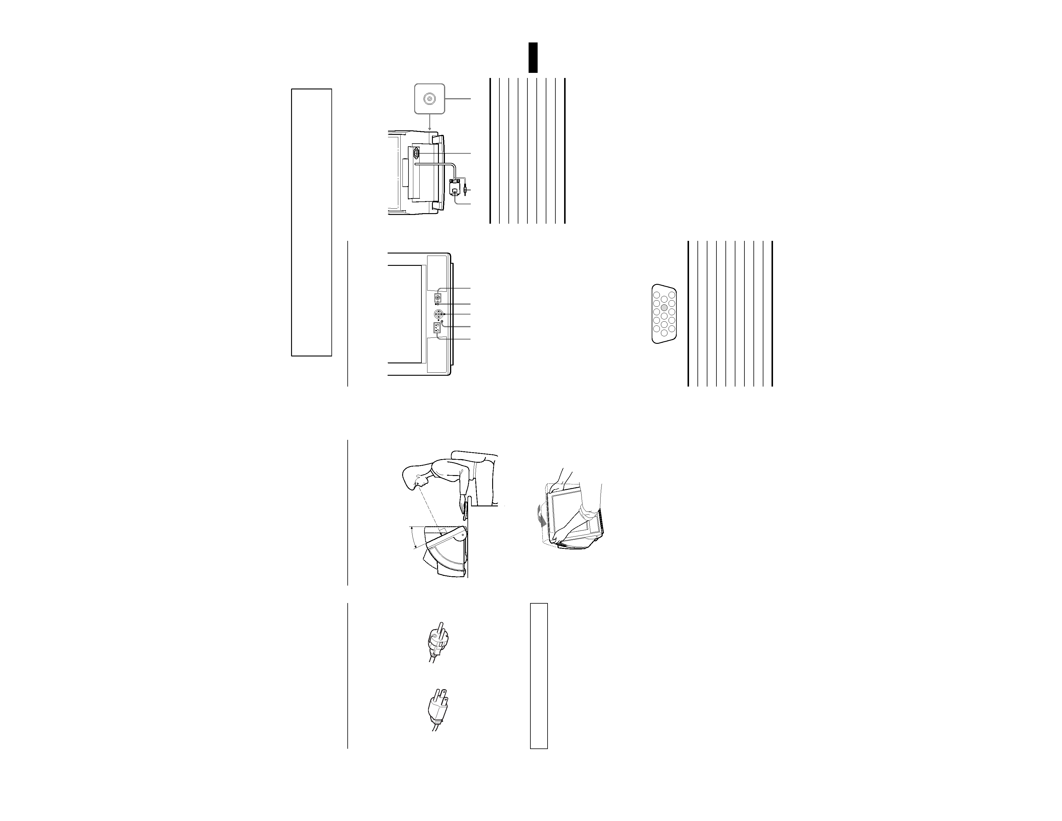
Positioning your monitor
This monitor is ergonomically designed to reduce eye and muscle
fatigue by allowing you to view the screen in a relaxed position.
To adjust the monitor correctly, place it in front of you and tilt the
screen backwards (max. 25
°) until your line of sight is at a right
angle to the screen.
When adjusting the monitor, hold it at the top with both hands as
shown below.
The equipment should be installed near an easily accessible
outlet.
Example of plug types
for 100 to 120 V AC
for 200 to 240 V AC
25
°
90
°
5
US
Identifying parts and controls
See the pages in parentheses for further details..
1 Volume buttons
These buttons adjust speaker volume.
2 MENU button (page 9)
This button is used to display the menu.
3 Control button (page 9)
The control button is used to make adjustments to the
monitor, including brightness and contrast adjustments.
4 % (mute) button
This button mutes sound. To restore sound, press the
%
(mute) button again or press the Volume Up button.
5 1 (power) switch and indicator (pages 7, 13, 16)
This button turns the monitor on and off. The power indicator
lights up in green when the monitor is turned on, and either
flashes in green and orange, or lights up in orange when the
monitor is in power saving mode.
6 Video signal cable (HD15) (page 6)
The connector of the cable inputs RGB video signals (0.700
Vp-p, positive) and sync signals.
* DDC (Display Data Channel) is a standard of VESA.
7 Audio plug (page 6)
This stereo audio plug inputs audio signals.
8 AC IN connector (page 7)
This connector provides AC power to the monitor.
9 Headphones jack
Standard mini-plug headphones can be connected. The
speakers are turned off when headphones are connected.
2
67
8
9
12 3 4
MENU
5
Rear
Front
Pin No.
Signal
1
Red
2
Green
3
Blue
4
ID (Ground)
5
DDC Ground*
6
Red Ground
7
Green Ground
8
Blue Ground
12345
6789 10
11 12 13 14 15
9
10
Ground
11
ID (Ground)
12
Bi-Directional Data (SDA)*
13
H. Sync
14
V. Sync
15
Data Clock (SCL)*
Pin No.
Signal