1
SERVICE MANUAL
MINI Hi-Fi COMPONENT SYSTEM
AEP Model
UK Model
E Model
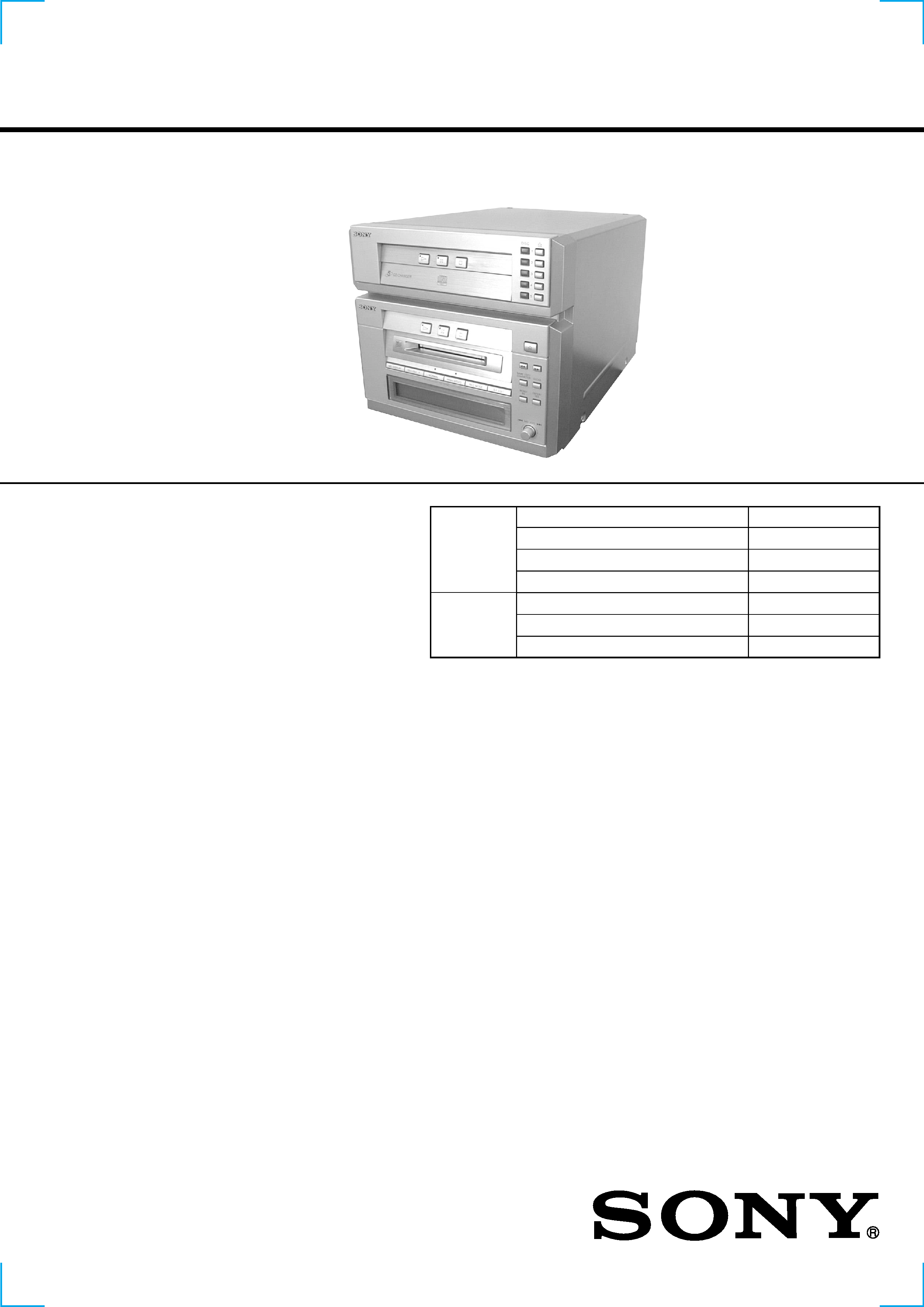
HMC-NX5MD
HMC-NX5MD is the CD player and MD
Deck section in DHC-NX5MD
CD
Section
Model Name Using Similar Mechanism
NEW
CD Mechanism Type
CDM53E-K4BD40
Base Unit Name Type
BU-K4BD40
Optical Pick-up Name
KSM-213DHAP/Z-NP
Model Name Using Similar Mechanism
NEW
MD Mechanism Type
MDM-7B
Optical Pick-up Name
KMS-260B/J1N
SPECIFICATIONS
MD
Section
CD player section
System
Compact disc and digital audio
system
Laser
Semiconductor laser
(
=780 nm)
Emission duration: continuous
Laser output
Max. 44.6
µW*
*This output is the value measured
at a distance of 200 mm from the
objective lens surface on the
Optical Pick-up Block with 7 mm
aperture.
Wavelength
780 790 nm
Frequency response
20 Hz 20 kHz (
±0.5 dB)
Signal-to-noise ratio
More than 90 dB
Dynamic range
More than 90 dB
MD deck section
System
MiniDisc digital audio system
Laser
Semiconductor laser
(
=780 nm)
Emission duration: continuous
Laser output
Max. 44.6
µW*
*This output is the value measured
at a distance of 200 mm from the
objective lens surface on the
Optical Pick-up Block with 7 mm
aperture.
Sampling frequency
44.1 kHz
Frequency response
20 Hz 20 kHz
General
Power requirements
European models:
230 V AC, 50/60 Hz
Other models:
120 V, 220 V or 230 240 V AC,
50/60 Hz Adjustable with voltage
selector
Power consumption
European models:
190 watts
Other models:
220 watts
Dimensions (w/h/d)
Approx. 225
× 202 × 356 mm
Mass
Approx. 4.3 kg
Supplied accessories:
AM loop aerial (1)
Remote Commander (1)
Batteries (2)
FM lead aerial (1)
Speaker cords (2)
Front speaker pads (8)
Design and specifications are subject to change
without notice.
2
SELF-DIAGNOSIS FUNCTION
The self-diagnosis function consists of error codes for customers which are displayed automatically when errors occur, and error codes which
show the error history in the test mode during servicing. For details on how to view error codes for the customer, refer to the following box
in the instruction manual. For details on how to check error codes during servicing, refer to the following "Procedure for using the Self-
Diagnosis Function (Error History Display Mode)".
Procedure for using the Self-Diagnosis Function (Error History Display Mode).
Note: Perform the self-diagnosis function in the "error history display mode" in the test mode. The following describes the least required
procedure. Be careful not to enter other modes by mistake. If you set other modes accidentally, press the MENU/NO button to exit
the mode.
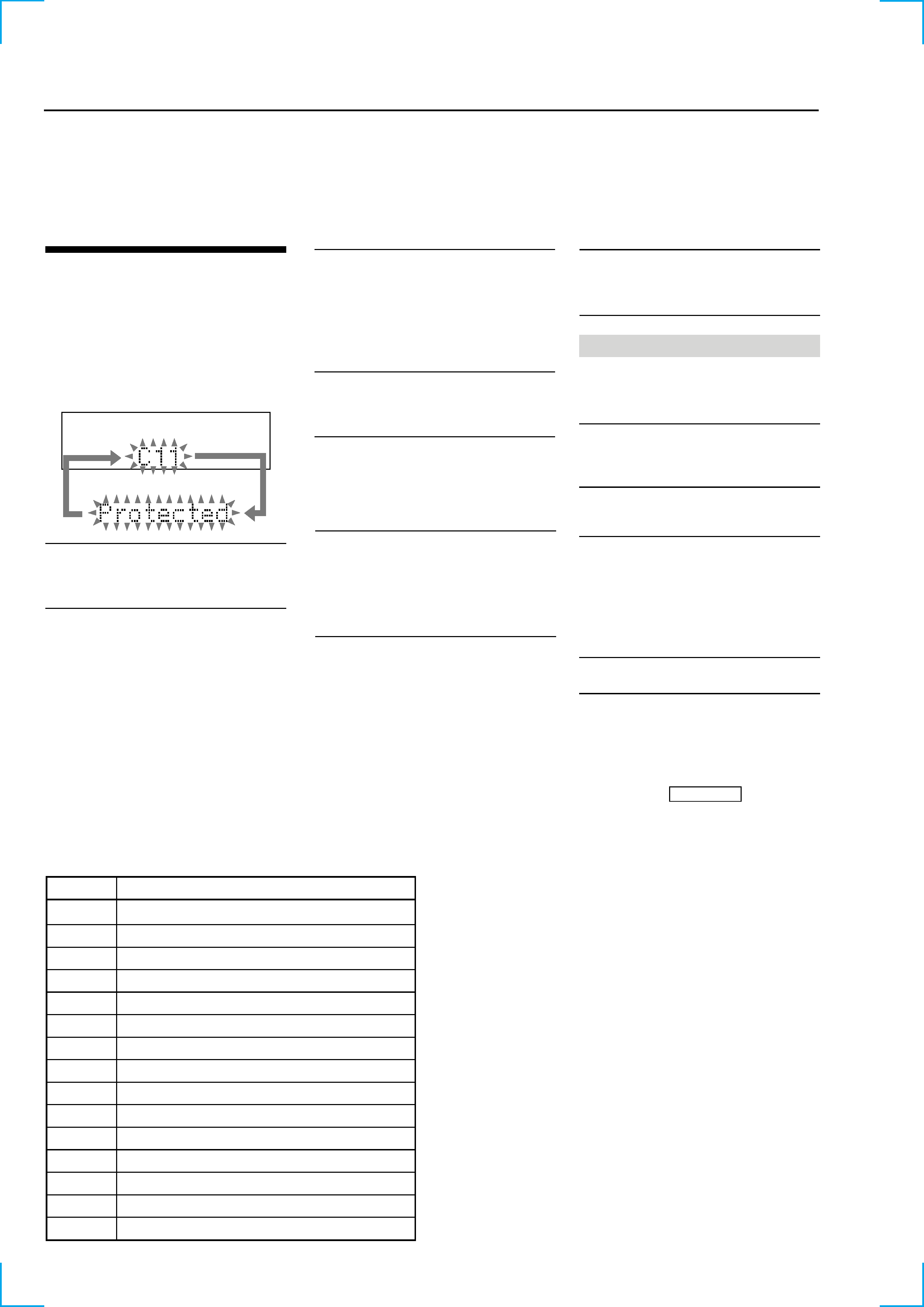
Self-diagnosis Display
This system has a Self-diagnosis display function
to let you know if there is a system malfunction.
The display shows a code made up of three or five
letters and a message alternately to show you the
problem. To solve the problem refer to the
following list. If any problem persists, consult
your nearest Sony dealer.
C11/Protected
The MD is protected against erasure.
cRemove the MD and slide the tab to close the
slot (page 27).
C12/Cannot Copy
You tried to record a CD or MD with a format
that the system does not support, such as a CD-
ROM.
cRemove the disc and turn off the system once,
then turn it on again.
C13/REC Error
Recording could not be performed properly.
cMove the system to a stable place, and start
recording over from the beginning.
The MD is dirty or scratched, or the MD does
not meet the standards.
cReplace the MD and start recording over from
the beginning.
C13/Read Error
The MD deck cannot read the disc information
properly.
cRemove the MD once, then insert it again.
C14/Toc Error
The MD deck cannot read the disc information
properly.
cReplace the MD.
cErase all the recorded contents of the MD
using the All Erase function on page 44.
C41/Cannot Copy
The sound source is a copy of a commercially
available music software, or you tried to record
a CD-R (Recordable CD).
cThe Serial Copy Management System
prevents making a digital copy (see page 71).
You cannot record a CD-R.
E0001/MEMORY NG
There is an error in the internal data that the
system needs in order to operate.
cConsult your nearest Sony dealer.
E0101/LASER NG
There is a problem with the optical pickup.
cThe optical pickup may have failed. Consult
your nearest Sony dealer.
Messages
One of the following messages may appear or
flash in the display during operation.
MD
Auto Cut
The MD deck is pausing the recording because
silence continued for about 30 seconds or more
during digital recording.
Blank Disc
The inserted recordable MD is new, or all
tracks on the MD have been erased.
Cannot Edit
· A pre-mastered MD is in the deck.
· You tried to edit during Programme or
Shuffle Play.
· You tried to change the recorded level or
perform Fade-in or Fade-out operation after
the Daily Timer or Recording Timer had
activated and turned on the power.
Cannot REC
The function is switched to MD.
Complete!
The editing operation of MDs is completed.
Description
Table of Error Codes
Error Code
10
12
20
21
22
23
24
30
31
40
41
42
43
50
51
Could not load
Loading switches combined incorrectly
Timed out without reading the top of PTOC
Could read top of PTOC, but detected error
Timed out without accessing UTOC
Timed out without reading UTOC
Error in UTOC
Could not start playback
Error in sector
Retry cause generated during normal recording
Retried in DRAM overflow
Retry occurred during TOC writing
Retry aborted during S.F editing
Other than access processing, and could not read address.
Focus NG occurred and overran.
3
1. Clicking the ENTER/YES button and the A (DISC 5) button while clicking the m (MD) button causes the program to enter test mode
and the message "Check" to be displayed on screen.
2. Rotate the MD JOG knob and when "[Service]" is displayed, press the ENTER/YES button.
3. Rotate the MD JOG knob and display "Err Display".
4. Pressing the ENTER/YES button sets the error history mode and displays "op rec tm".
5. Select the contents to be displayed or executed using the MD JOG knob.
6. Pressing the MD JOG knob will display or execute the contents selected.
7. Pressing the MD JOG knob another time returns to step 4.
8. Pressing the MENU/NO button displays "Err Display" and exits the error history mode.
9. To exit from test mode, enter MD mode and click the STR REPEAT button. The program will enter standby mode and then exit test mode.
ITEMS OF ERROR HISTORY MODE ITEMS AND CONTENTS
Selecting the Test Mode
Display
op rec tm
op play tm
spdl rp tm
retry err
total err
err history
retry adrs
er refresh
op change
spdl change
History
Displays the total recording time.
When the total recording time is more than 1 minute, displays the hour and minute
When less than 1 minute, displays "Under 1 min"
The display time is the time the laser is set to high power, which is about 1/4 of the actual recording time.
Displays the total playback time.
When the total playback time is more than 1 minute, displays the hour and minute
When less than 1 minute, displays "Under 1 min"
Displays the total rotating time of the spindle motor.
When the total rotating time is more than 1 minute, displays the hour and minute
When less than 1 minute, displays "Under 1 min"
Displays the total number of retry errors during recording and playback
Displays "r xx p yy". xx is the number of errors during recording. yy is the number of errors during playback.
This is displayed in hexadecimal from 00 to FF.
Displays the total number of errors
Displays "total xx". This is displayed in hexadecimal from 00 to FF.
Displays the past ten errors.
Displays "0x ErrCd@@".
X is the history number. The younger the number, the more recent is the history (00 is the latest). @@ is the error
code.
Select the error history number using the AMS knob.
Displays the past five retry addresses.
Displays "xx ADRS yyyy", xx is the history number, yyyy is the cluster with the retry error.
Select the error history number using the AMS knob.
Mode for erasing the error and retry address histories
Procedure
1. Press the AMS knob when displayed as "er refresh".
2. Press the YES button when the display changes to "er refresh?".
When "complete!" is displayed, it means erasure has completed.
Be sure to check the following after executing this mode.
*Data has been erased.
*Perform recording and playback, and check that the mechanism is normal.
Mode for erasing the total time of op rec tm, op play tm.
These histories are based on the time of replacement of the optical pick-up. If the optical pick-up has been
replaced, perform this procedure and erase the history.
Procedure
1. Press the AMS knob when displayed as "op change".
2. Press the YES button when the display changes to "op change?".
When "Complete!" is displayed, it means erasure has completed.
Mode for erasing the total spdl rp tm time
These histories are based on the time of replacement of the spindle motor. If the spindle motor has been replaced,
perform this procedure and erase the history.
Procedure
1. Press the AMS knob when displayed as "spdl change"
2. Press the YES button when the display changes to "spdl change?"
When "Complete!" is displayed, it means erasure has completed.
4
SAFETY-RELATED COMPONENT WARNING!!
COMPONENTS IDENTIFIED BY MARK 0 OR DOTTED
LINE WITH MARK 0 ON THE SCHEMATIC DIAGRAMS
AND IN THE PARTS LIST ARE CRITICAL TO SAFE
OPERATION. REPLACE THESE COMPONENTS WITH
SONY PARTS WHOSE PART NUMBERS APPEAR AS
SHOWN IN THIS MANUAL OR IN SUPPLEMENTS PUB-
LISHED BY SONY.
SECTION 1
SERVICING NOTES
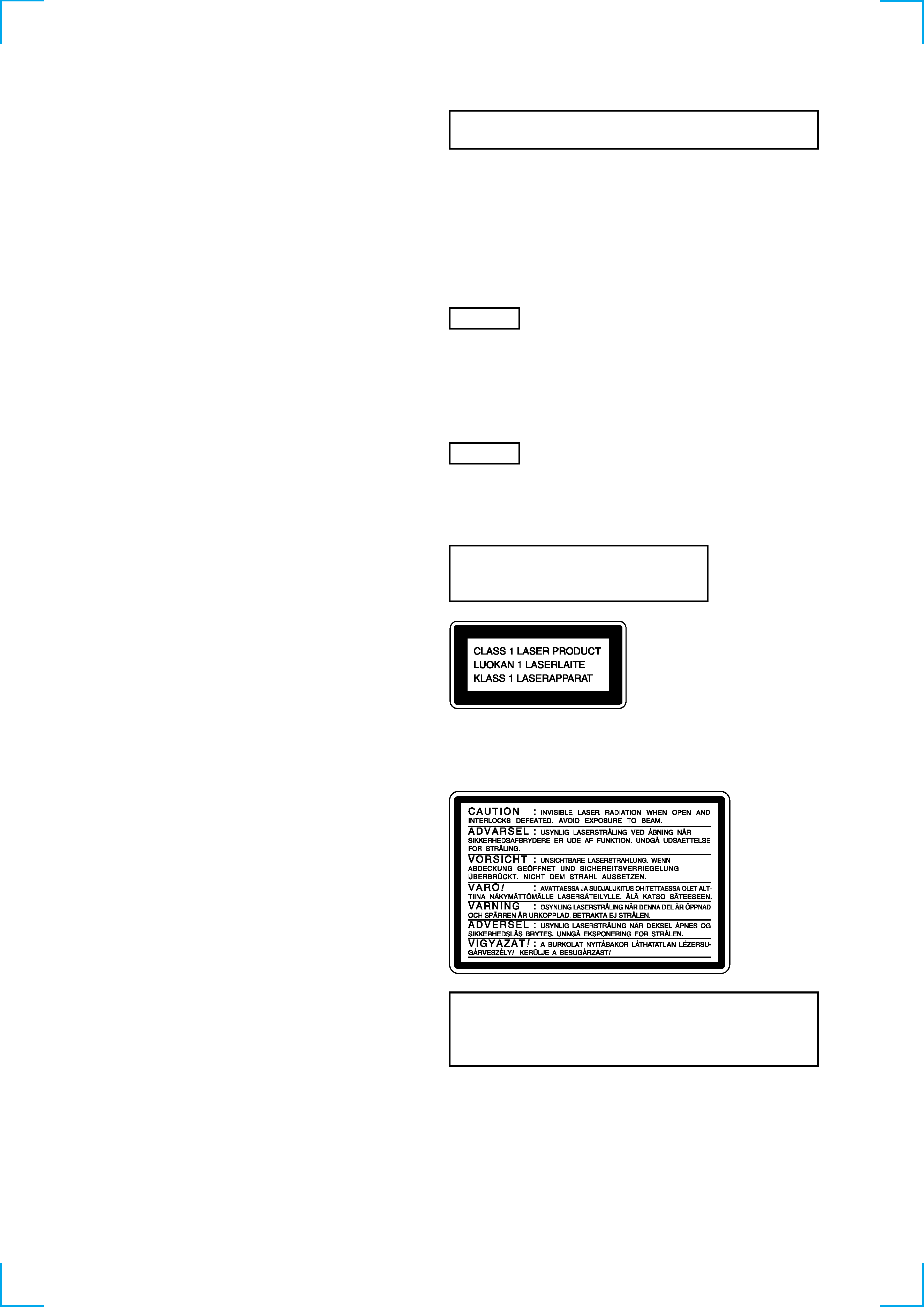
This appliance is classified as a CLASS 1 LASER product. The
CLASS 1 LASER PRODUCT MARKING is located on the rear
exterior.
Laser component in this product is capable
of emitting radiation exceeding the limit for
Class 1.
CAUTION
Use of controls or adjustments or performance of procedures
other than those specified herein may result in hazardous radia-
tion exposure.
Notes on chip component replacement
· Never reuse a disconnected chip component.
· Notice that the minus side of a tantalum capacitor may be
damaged by heat.
Flexible Circuit Board Repairing
· Keep the temperature of soldering iron around 270°C
during repairing.
· Do not touch the soldering iron on the same conductor of the
circuit board (within 3 times).
· Be careful not to apply force on the conductor when soldering
or unsoldering.
NOTES ON HANDLING THE OPTICAL PICK-UP
BLOCK OR BASE UNIT
The laser diode in the optical pick-up block may suffer electrostatic
break-down because of the potential difference generated by the
charged electrostatic load, etc. on clothing and the human body.
During repair, pay attention to electrostatic break-down and also
use the procedure in the printed matter which is included in the
repair parts.
The flexible board is easily damaged and should be handled with
care.
FOR CD
NOTES ON LASER DIODE EMISSION CHECK
The laser beam on this model is concentrated so as to be focused on
the disc reflective surface by the objective lens in the optical pick-
up block. Therefore, when checking the laser diode emission, ob-
serve from more than 30 cm away from the objective lens.
FOR MD
NOTES ON LASER DIODE EMISSION CHECK
Never look into the laser diode emission from right above when
checking it for adjustment. It is feared that you will lose your sight.
This caution
label is located
inside the unit.
TABLE OF CONTENTS
1. SERVICING NOTES ......................................................... 4
2. GENERAL .......................................................................... 12
3. DISASSEMBLY
3-1. Case ..................................................................................... 13
3-2. Front Panel Section ............................................................. 13
3-3. CD Mechanism Deck Section ............................................. 14
3-4. MD Mechanism Deck Block ............................................... 14
3-5. CD Base Unit ...................................................................... 15
3-6. Main Board ......................................................................... 15
3-7. Fitting Base (Guide) Assy, Bracket (Chassis) and
Magnet Assy ....................................................................... 16
3-8. Tray (Sub) ........................................................................... 16
3-9. Chassis (Mold B) Section, Stocker Section and
Slider (Selection) ................................................................ 17
3-10. Gears Installation .............................................................. 17
3-11. Slider (Selection) Installation ............................................ 18
3-12. Stocker Section Installation ............................................... 18
3-13. Chassis (Mold B) Section Installation .............................. 19
3-14. MD Mechanism Deck Section .......................................... 19
3-15. BD (MD) Board ................................................................ 20
4. TEST MODE ...................................................................... 21
5. ELECTRICAL ADJUSTMENT .................................... 27
6. DIAGRAMS
6-1. Circuit Boards Location ...................................................... 39
6-2. Block Diagrams ................................................................... 41
6-3. Schematic Diagram CD Section .................................... 44
6-4. Printed Wiring Board CD Section ................................. 45
6-5. Printed Wiring Board MD Section ................................ 46
6-6. Schematic Diagram MD Section (1/2) .......................... 47
6-7. Schematic Diagram MD Section (2/2) .......................... 48
6-8. Schematic Diagram Main Section (1/2) ........................ 49
6-9. Schematic Diagram Main Section (2/2) ........................ 50
6-10. Printed Wiring Board Main Section ............................ 51
6-11. Schematic Diagram Digital Section ............................ 52
6-12. Printed Wiring Board Digital Section ......................... 53
6-13. Schematic Diagram Panel Section .............................. 54
6-14. Printed Wiring Board Panel Section ............................ 55
6-15. Schematic Diagram CD Mechanism Section .............. 56
6-16. Printed Wiring Board CD Mechanism Section ........... 57
6-17. IC Block Diagrams ............................................................ 58
6-18. IC Pin Function ................................................................. 62
7. EXPLODED VIEW
7-1. Case, Chassis Section ......................................................... 71
7-2. Front Panel Section ............................................................. 72
7-3. CD Mechanism Deck Section-1 .......................................... 73
7-4. CD Mechanism Deck Section-2 .......................................... 74
7-5. CD Base Unit Section ......................................................... 75
7-6. MD Mechanism Section-1 .................................................. 76
7-7. MD Mechanism Section-2 .................................................. 77
8. ELECTRICAL PARTS LIST ........................................ 78
5
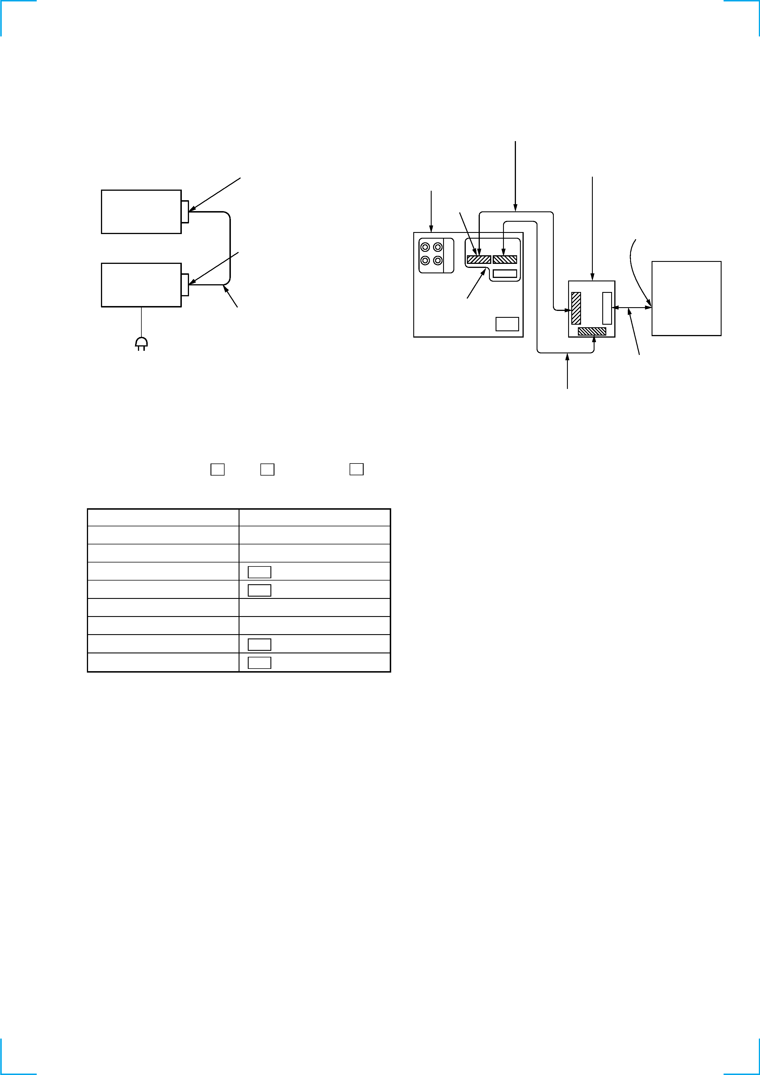
POWER SUPPLY DURING SERVICING
· As this set has not own power supply, it does not operate indepen-
dently. Therefore, during servicing, connect it to the Pre-Main
amplifier and Tuner Unit (STR-NX5MD) of DHC-NX5MD.
If STR-NX5MD are not available, use the Power Feed Jig (PFJ-
1) and Relay Connector Jig.
In this case, after turn on the POWER switch on the Power Feed
Jig, supply power with the following methods.
Procedure:
1. Press three buttons of G (MD), A (DISC 1), and s (CD)
simultaneously.
Set
SYSTEM CONTROL terminal
SYSTEM CONTROL terminal
Connector cable (19P)
Pre-Main AMP
and Tuner Unit
AC IN
Power feed jig
(PFJ-1)
Connector cable (17P) of
attachment to power feed jig
Relay connector jig
(J-2501-197-A)
CN101 (19P)
SYSTEM CONTROL
terminal
system cable
Exclusive cable (15P)
P707, P909
Set
CDP/MD
ST
Connection:
function
button
CD AMS
AMS
AMS +
AMS +
FR
m
FF
M
MD AMS
AMS
AMS +
AMS +
FR
m
FF
M