SERVICE MANUAL
Sony Corporation
Home Audio Division
Published by Sony Techno Create Corporation
US Model
Canadian Model
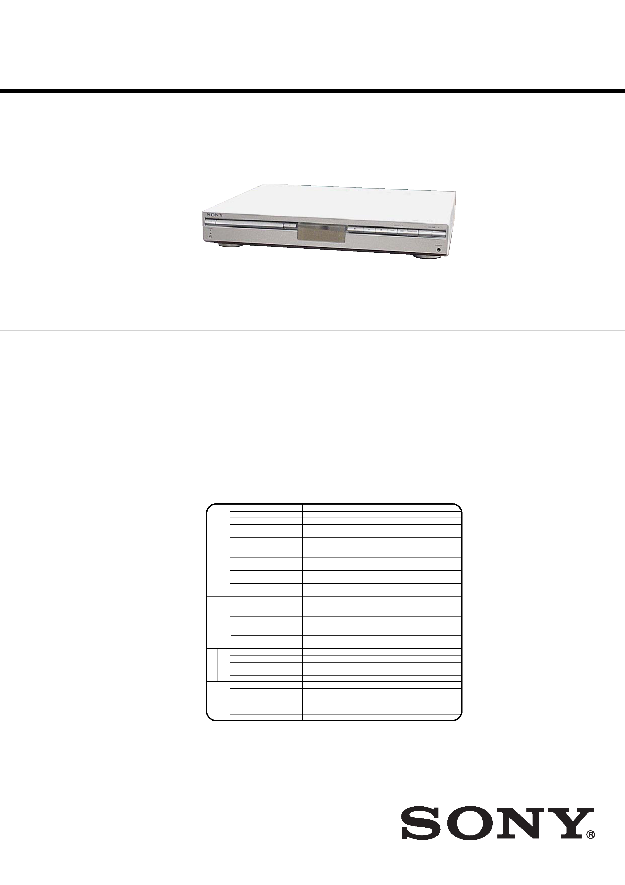
HCD-SB100
AEP Model
UK Model
E Model
Australian Model
HCD-SB100/SB200
DVD RECEIVER
9-879-182-09
2006B16-1
© 2006.02
Ver. 1.8 2006.02
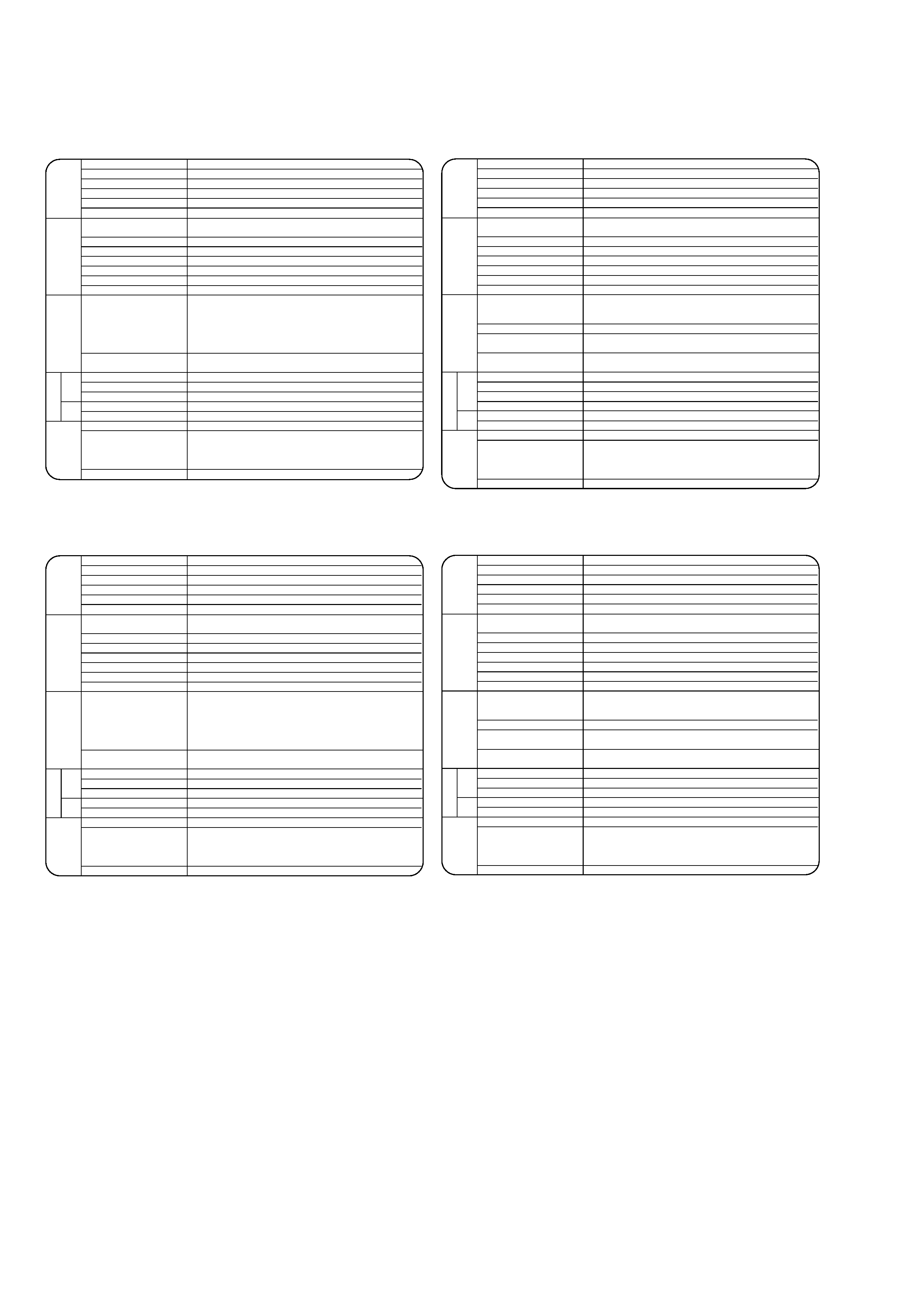
SPECIFICATIONS
HCD-SB100/SB200
· HCD-SB100/SB200 are the amplifier, DVD/CD and
tuner section in DAV-SB100/SB200.
·Abbreviation
AUS: Australian model
CND : Canadian model
EA
: Saudi Arabia model
EE
: East European model
RU
: Russian model
SP
: Singapore model
Photo: HCD-SB100
Manufactured under license from Dolby Laboratories."Dolby", "Pro Logic",
and the double-D symbol are trademarks of Dolby Laboratories.
Confidential Unpublished works. Copyright 1992-1997 Dolby
Laboratories. All rights reserved.
Manufactured under license from Digital Theater Systems, Inc.
US Pat. No. 5,451,942 5,956,674, 5,974,380, 5,978,762 and other
worldwide patents issued and pending. "DTS" and "DTS Digital Surround"
are registered trademarks of Digital Theater Systems, Inc. Copyright 1996,
2000 Digital Theater Systems, Inc. All rights reserved.
(SB100: US, CND models)
Power supply
120V AC, 60Hz
Power consumption
70W, No more than 1 W (120V AC) (at the power saving mode)
Mass
kg
External dimensions (WxHxD)
430 x 70 x 383.5 mm
Operating conditions
Temperature: 5
°C to 35°C, Operation status: Horizontal
Operating humidity
5% to 85%
Laser
Semiconductor laser, wavelength 650 nm for VCD and DVD,
wavelength 780 nm for CD
Emission duration
Continuous
Signal system
NTSC 525/60
Frequency response (audio)
2 Hz ~ 20 kHz (
±1.0 dB)
Signal-to-noise ratio (audio)
More than 75 dB (1 kHz, NOP, 20 kHz LPF/A-Filter)
Dynamic range (audio)
More than 70 dB
Harmonic distortion (audio)
0.5 % (1 kHz, at 12W position) (20 kHz LPF/A-Filter)
Inputs
(AUDIO IN):
Sensitivity: 800 m V
Impedance: 50 kilohms
Video output
1.0 V (p-p), 75
, negative sync., RCA jack
S VIDEO OUT
(Y) 1.0 V (p-p), 75 ohms, negative sync, Mini DIN 4-pin x 1
(C) 0.286 V (p-p) 75 ohms
COMPONENT VIDEO OUT
(Y) 1.0 V (p-p), 75 ohms, negative sync, RCA jack x 1
(PB/CB)/(PR/CR) 0.7 V (p-p), 75 ohms, RCA jack x 2
Tuning Range
87.5 - 108 MHz
Intermediate Frequency
10.7 MHz
Signal-to Noise Ratio
60 dB (Mono)
Tuning Range
522 - 1,611 kHz
Intermediate Frequency
450 kHz
Stereo mode
50W + 50W (8
at 1 kHz, THD 10 %)
Surround mode
Front: 50W + 50W
Centre*: 50W
Surround*: 50W + 50W (8
at 1 kHz, THD 10 %)
Subwoofer*: 80W (4
at 50 Hz, THD 10 %)
Outputs
PHONES: (32
, 25mW)
[General]
[CD/D
VD]
[Video]
[Amplifier]
(* Depending on the sound mode
settings and the source, there
may be no sound output.)
[T
uner]
[FM]
AM
[MW]
VIDEO
4.7
Continued on next page
2
HCD-SB100/SB200
Ver. 1.1
(SB100: AEP, UK, RU, EE models)
(SB100: EA, SP, AUS models)
(SB200: AEP, UK, RU, EE models)
(SB200: SP, AUS models)
Power supply
220-240V AC, 50/60Hz
Power consumption
70W, No more than 1 W (220-240V AC) (at the power saving mode)
Mass
kg
External dimensions (WxHxD)
430 x 70 x 383.5 mm
Operating conditions
Temperature: 5
°C to 35°C, Operation status: Horizontal
Operating humidity
5% to 85%
Laser
Semiconductor laser, wavelength 650 nm for VCD and DVD,
wavelength 780 nm for CD
Emission duration
Continuous
Signal system
PAL 625/50, NTSC 525/60
Frequency response (audio)
2 Hz ~ 20 kHz (
±1.0 dB)
Signal-to-noise ratio (audio)
More than 75 dB (1 kHz, NOP, 20 kHz LPF/A-Filter)
Dynamic range (audio)
More than 70 dB
Harmonic distortion (audio)
0.5 % (1 kHz, at 12W position) (20 kHz LPF/A-Filter)
Inputs
(AUDIO IN):
Sensitivity: 800 m V
Impedance: 50 kilohms
SCART (AUDIO IN):
Sensitivity: 800 m V
Impedance: 50 kilohms
Video output
1.0 V (p-p), 75
, negative sync., RCA jack
EURO AV (TO TV)
Tuning Range
87.5 - 108 MHz
Intermediate Frequency
10.7 MHz
Signal-to Noise Ratio
60 dB (Mono)
Tuning Range
522 - 1,611 kHz
Intermediate Frequency
450 kHz
Stereo mode
50W + 50W (8
at 1 kHz, THD 10 %)
Surround mode
Front: 50W + 50W
Centre*: 50W
Surround*: 50W + 50W (8
at 1 kHz, THD 10 %)
Subwoofer*: 80W (4
at 50 Hz, THD 10 %)
Outputs
PHONES: (32
, 25mW)
[General]
[CD/D
VD]
[Video]
[Amplifier]
(* Depending on the sound mode
settings and the source, there
may be no sound output.)
[T
uner]
[FM]
AM
[MW]
VIDEO
4.7
Power supply
220-240V AC, 50/60Hz
Power consumption
70W, No more than 1 W (220-240V AC) (at the power saving mode)
Mass
kg
External dimensions (WxHxD)
430 x 70 x 383.5 mm
Operating conditions
Temperature: 5
°C to 35°C, Operation status: Horizontal
Operating humidity
5% to 85%
Laser
Semiconductor laser, wavelength 650 nm for VCD and DVD,
wavelength 780 nm for CD
Emission duration
Continuous
Signal system
PAL 625/50, NTSC 525/60
Frequency response (audio)
2 Hz ~ 20 kHz (
±1.0 dB)
Signal-to-noise ratio (audio)
More than 75 dB (1 kHz, NOP, 20 kHz LPF/A-Filter)
Dynamic range (audio)
More than 70 dB
Harmonic distortion (audio)
0.5 % (1 kHz, at 12W position) (20 kHz LPF/A-Filter)
Inputs
(AUDIO IN):
Sensitivity: 800 m V
Impedance: 50 kilohms
Video output
1.0 V (p-p), 75
, negative sync., RCA jack
S VIDEO OUT
(Y) 1.0 V (p-p), 75 ohms, negative sync, Mini DIN 4-pin x 1
(C) 0.286 V (p-p) 75 ohms
COMPONENT VIDEO OUT
(Y) 1.0 V (p-p), 75 ohms, negative sync, RCA jack x 1
(PB/CB)/(PR/CR) 0.7 V (p-p), 75 ohms, RCA jack x 2
Tuning Range
87.5 - 108 MHz
Intermediate Frequency
10.7 MHz
Signal-to Noise Ratio
60 dB (Mono)
Frequency Response (AUS)
150 - 10,000 Hz
Tuning Range
522 - 1,611 kHz
Intermediate Frequency
450 kHz
Stereo mode
50W + 50W (8
at 1 kHz, THD 10 %)
Surround mode
Front: 50W + 50W (THD 10 %)
Centre*: 50W
Surround*: 50W + 50W (8
at 1 kHz, THD 10 %)
Subwoofer*: 80W (4
at 50 Hz, THD 10 %)
Output
PHONES: (32
, 25mW)
[General]
[CD/D
VD]
[Video]
[Amplifier]
(* Depending on the sound mode
settings and the source, there
may be no sound output.)
[T
uner]
[FM]
AM
[MW]
4.7
VIDEO
Power supply
220-240V AC, 50/60Hz
Power consumption
100W, No more than 1 W (220-240V AC) (at the power saving mode)
Mass
kg
External dimensions (WxHxD)
430 x 70 x 370 mm
Operating conditions
Temperature: 5
°C to 35°C, Operation status: Horizontal
Operating humidity
5% to 85%
Laser
Semiconductor laser, wavelength 650 nm for VCD and DVD,
wavelength 780 nm for CD
Emission duration
Continuous
Signal system
PAL, NTSC
Frequency response (audio)
2 Hz ~ 20 kHz (
±1.0 dB)
Signal-to-noise ratio (audio)
More than 75 dB (1 kHz, NOP, 20 kHz LPF/A-Filter)
Dynamic range (audio)
More than 70 dB
Harmonic distortion (audio)
0.5 % (1 kHz, at 12W position) (20 kHz LPF/A-Filter)
Inputs
(AUDIO IN):
Sensitivity: 800 m V
Impedance: 50 kilohms
SCART (AUDIO IN):
Sensitivity: 800 m V
Impedance: 50 kilohms
Video output
1.0 V (p-p), 75
, negative sync., RCA jack
EURO AV (TO TV)
Tuning Range
87.5 - 108 MHz
Intermediate Frequency
10.7 MHz
Signal-to Noise Ratio
60 dB (Mono)
Tuning Range
522 - 1,611 kHz
Intermediate Frequency
450 kHz
Stereo mode
80W + 80W (6
at 1 kHz, THD 10 %)
Surround mode
Front: 80W + 80W
Centre*: 80W
Surround*: 80W + 80W (6
at 1 kHz, THD 10 %)
Subwoofer*: 150W (3
at 50 Hz, THD 10 %)
Outputs
PHONES: (32
, 25mW)
[General]
[CD/D
VD]
[Video]
[Amplifier]
(* Depending on the sound mode
settings and the source, there
may be no sound output.)
[FM]
AM
[MW]
[T
uner]
4.9
VIDEO
Power supply
220-240V AC, 50/60Hz
Power consumption
100W, No more than 1 W (220-240V AC) (at the power saving mode)
Mass
kg
External dimensions (WxHxD)
430 x 70 x 370 mm
Operating conditions
Temperature: 5
°C to 35°C, Operation status: Horizontal
Operating humidity
5% to 85%
Laser
Semiconductor laser, wavelength 650 nm for VCD and DVD,
wavelength 780 nm for CD
Emission duration
Continuous
Signal system
PAL, NTSC
Frequency response (audio)
2 Hz ~ 20 kHz (
±1.0 dB)
Signal-to-noise ratio (audio)
More than 75 dB (1 kHz, NOP, 20 kHz LPF/A-Filter)
Dynamic range (audio)
More than 70 dB
Harmonic distortion (audio)
0.5 % (1 kHz, at 12W position) (20 kHz LPF/A-Filter)
Inputs
(AUDIO IN):
Sensitivity: 800 m V
Impedance: 50 kilohms
Video output
1.0 V (p-p), 75
, negative sync., RCA jack
S VIDEO OUT
(Y) 1.0 V (p-p), 75 ohms, negative sync, Mini DIN 4-pin x 1
(C) 0.286 V (p-p) 75 ohms
COMPONENT VIDEO OUT
(Y) 1.0 V (p-p), 75 ohms, negative sync, RCA jack x 1
(PB/CB)/(PR/CR) 0.7 V (p-p), 75 ohms, RCA jack x 2
Tuning Range
87.5 - 108 MHz
Intermediate Frequency
10.7 MHz
Signal-to Noise Ratio
60 dB (Mono)
Tuning Range
522 - 1,611 kHz
Intermediate Frequency
450 kHz
Stereo mode
80W + 80W (6
at 1 kHz, THD 10 %)
Surround mode
Front: 80W + 80W
Centre*: 80W
Surround*: 80W + 80W (6
at 1 kHz, THD 10 %)
Subwoofer*: 150W (3
at 50 Hz, THD 10 %)
Outputs
PHONES: (32
, 25mW)
[T
uner]
[General]
[CD/D
VD]
[Video]
[Amplifier]
Designs and specifications are subject to change without notice.
(* Depending on the sound mode
settings and the source, there
may be no sound output.)
[FM]
AM
[MW]
4.9
VIDEO
3
HCD-SB100/SB200
Ver. 1.1
SAFETY-RELATED COMPONENT WARNING!!
COMPONENTS IDENTIFIED BY MARK 0 OR DOTTED LINE
WITH MARK 0 ON THE SCHEMATIC DIAGRAMS AND IN
THE PARTS LIST ARE CRITICAL TO SAFE OPERATION.
REPLACE THESE COMPONENTS WITH SONY PARTS WHOSE
PART NUMBERS APPEAR AS SHOWN IN THIS MANUAL OR
IN SUPPLEMENTS PUBLISHED BY SONY.
ATTENTION AU COMPOSANT AYANT RAPPORT
À LA SÉCURITÉ!
LES COMPOSANTS IDENTIFIÉS PAR UNE MARQUE 0 SUR
LES DIAGRAMMES SCHÉMATIQUES ET LA LISTE DES
PIÈCES
SONT
CRITIQUES
POUR
LA
SÉCURITÉ
DE
FONCTIONNEMENT. NE REMPLACER CES COM- POSANTS
QUE PAR DES PIÈCES SONY DONT LES NUMÉROS SONT
DONNÉS DANS CE MANUEL OU DANS LES SUPPLÉMENTS
PUBLIÉS PAR SONY.
SAFETY CHECK-OUT
After correcting the original service problem, perform the following
safety check before releasing the set to the customer:
Check the antenna terminals, metal trim, "metallized" knobs, screws,
and all other exposed metal parts for AC leakage.
Check leakage as described below.
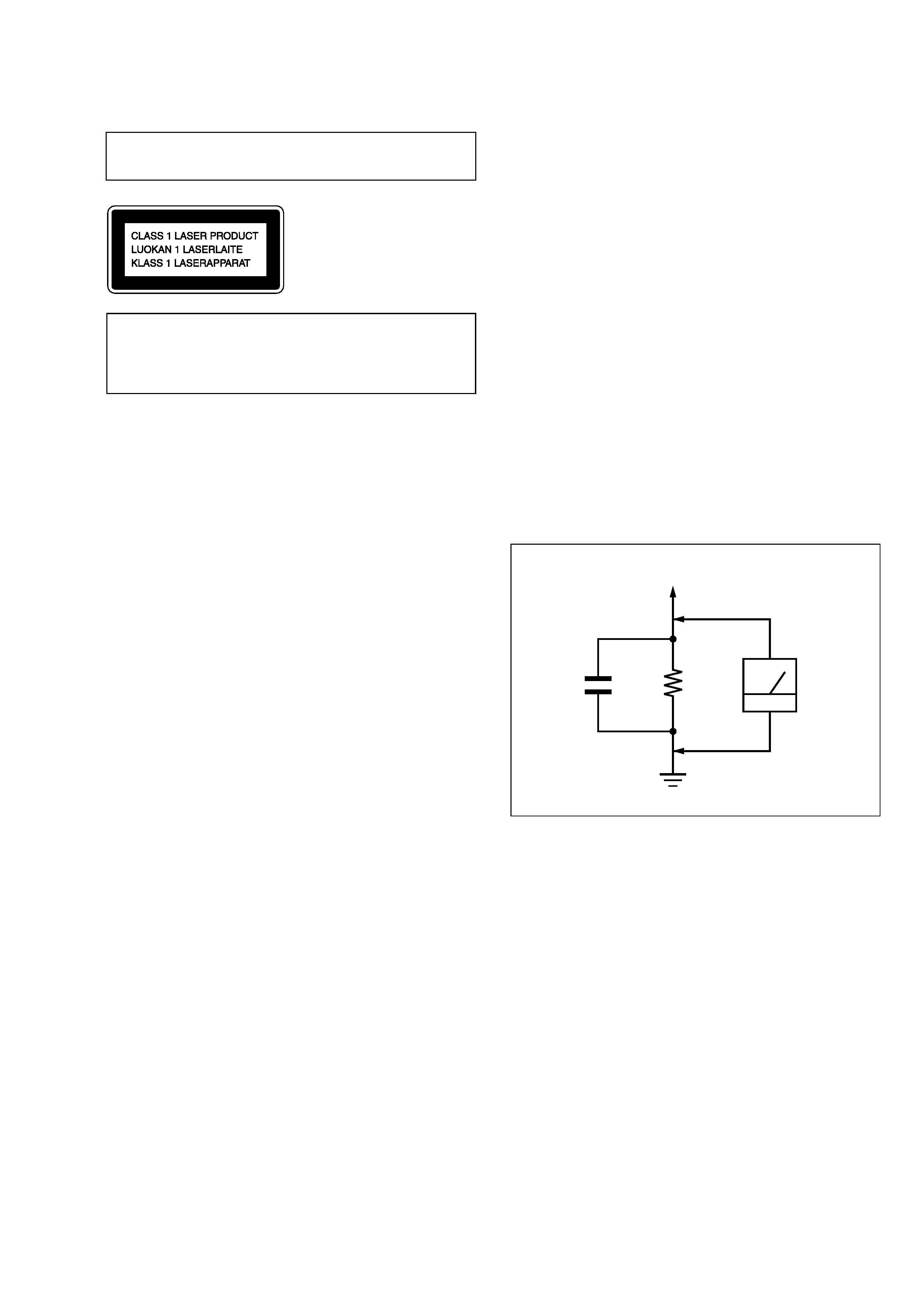
LEAKAGE TEST
The AC leakage from any exposed metal part to earth ground and
from all exposed metal parts to any exposed metal part having a
return to chassis, must not exceed 0.5 mA (500 microamperes.).
Leakage current can be measured by any one of three methods.
1. A commercial leakage tester, such as the Simpson 229 or RCA
WT-540A. Follow the manufacturers' instructions to use these
instruments.
2. A battery-operated AC milliammeter. The Data Precision 245
digital multimeter is suitable for this job.
3. Measuring the voltage drop across a resistor by means of a
VOM or battery-operated AC voltmeter. The "limit" indication
is 0.75 V, so analog meters must have an accurate low-voltage
scale. The Simpson 250 and Sanwa SH-63Trd are examples
of a passive VOM that is suitable. Nearly all battery operated
digital multimeters that have a 2 V AC range are suitable. (See
Fig. A)
Fig. A.
Using an AC voltmeter to check AC leakage.
1.5 k
0.15
µF
AC
voltmeter
(0.75 V)
To Exposed Metal
Parts on Set
Earth Ground
CAUTION
Use of controls or adjustments or performance of procedures
other than those specified herein may result in hazardous radiation
exposure.
Notes on chip component replacement
· Never reuse a disconnected chip component.
· Notice that the minus side of a tantalum capacitor may be
damaged by heat.
Flexible Circuit Board Repairing
· Keep the temperature of the soldering iron around 270 °C
during repairing.
· Do not touch the soldering iron on the same conductor of the
circuit board (within 3 times).
· Be careful not to apply force on the conductor when soldering
or unsoldering.
Laser component in this product is capable of emitting radiation
exceeding the limit for Class 1.
This appliance is classified as
a CLASS 1 LASER product.
The
CLASS
1
LASER
PRODUCT MARKING is
located on the rear exterior.

4
HCD-SB100/SB200
Ver. 1.1
TABLE OF CONTENTS
1.
SERVICING NOTES ................................................ 5
2.
GENERAL ................................................................... 6
3.
DISASSEMBLY
3-1.
Disassembly Flow ........................................................... 12
3-2.
Case ................................................................................. 13
3-3.
Front Panel Assy Section ................................................. 13
3-4.
POWER Board ................................................................ 14
3-5.
DVD Board ...................................................................... 15
3-6.
DVD Mechanism Deck ................................................... 16
3-7.
Tuner Pack ....................................................................... 16
3-8.
AMP Board ...................................................................... 17
4.
ELECTRICAL TROUBLE
SHOOTING GUIDE .................................................. 18
5.
TEST MODE ............................................................... 42
6.
ELECTRICAL ADJUSTMENT ............................. 43
7.
DIAGRAMS
7-1.
Block Diagram DVD Section ................................... 46
AUDIO Section .......................................................... 47
POWER Section ........................................................ 48
7-2.
Printed Wiring Board
AMP Section SB100 (Component Side) ................... 49
7-3.
Printed Wiring Board
AMP Section SB100 (Conductor Side) ..................... 50
7-4.
Printed Wiring Board
AMP Section SB200 (Component Side) ................... 51
7-5.
Printed Wiring Board
AMP Section SB200 (Conductor Side) ..................... 52
7-6.
Schematic Diagram AMP Section (1/6) ................... 53
7-7.
Schematic Diagram AMP Section (2/6) ................... 54
7-8.
Schematic Diagram AMP Section (3/6) ................... 55
7-9.
Schematic Diagram AMP Section (4/6) (SB100) ..... 56
7-10. Schematic Diagram AMP Section (5/6) (SB200) ..... 57
7-11. Schematic Diagram AMP Section (6/6) ................... 58
7-12. Printed Wiring Board DVD Section ......................... 59
7-13. Schematic Diagram DVD Section (1/3) ................... 60
7-14. Schematic Diagram DVD Section (2/3) ................... 61
7-15. Schematic Diagram DVD Section (3/3) ................... 62
7-16. Printed Wiring Board FRONT Section ..................... 63
7-17. Schematic Diagram FRONT Section ....................... 64
7-18. Printed Wiring Board POWER Section (SB100) ..... 65
7-19. Printed Wiring Board POWER Section (SB200) ..... 66
7-20. Schematic Diagram
POWER Section (1/2) (SB100) ................................. 67
7-21. Schematic Diagram
POWER Section (2/2) (SB200) ................................. 68
8.
EXPLODED VIEWS
8-1.
Overall Section ................................................................ 77
8-2.
Chassis Section ................................................................ 78
8-3.
DVD Mechanism Section ................................................ 79
9.
ELECTRICAL PARTS LIST .................................. 80
5
HCD-SB100/SB200
SECTION 1
SERVICING NOTES
NOTES ON HANDLING THE OPTICAL PICK-UP BLOCK
OR BASE UNIT
The laser diode in the optical pick-up block may suffer electrostatic
break-down because of the potential difference generated by the
charged electrostatic load, etc. on clothing and the human body.
During repair, pay attention to electrostatic break-down and also
use the procedure in the printed matter which is included in the
repair parts.
The flexible board is easily damaged and should be handled with
care.
NOTES ON LASER DIODE EMISSION CHECK
The laser beam on this model is concentrated so as to be focused on
the disc reflective surface by the objective lens in the optical pick-
up block. Therefore, when checking the laser diode emission,
observe from more than 30 cm away from the objective lens.
LASER DIODE AND FOCUS SEARCH OPERATION
CHECK
Carry out the "S curve check" in "CD section adjustment" and check
that the S curve waveform is output several times.
Ver. 1.5
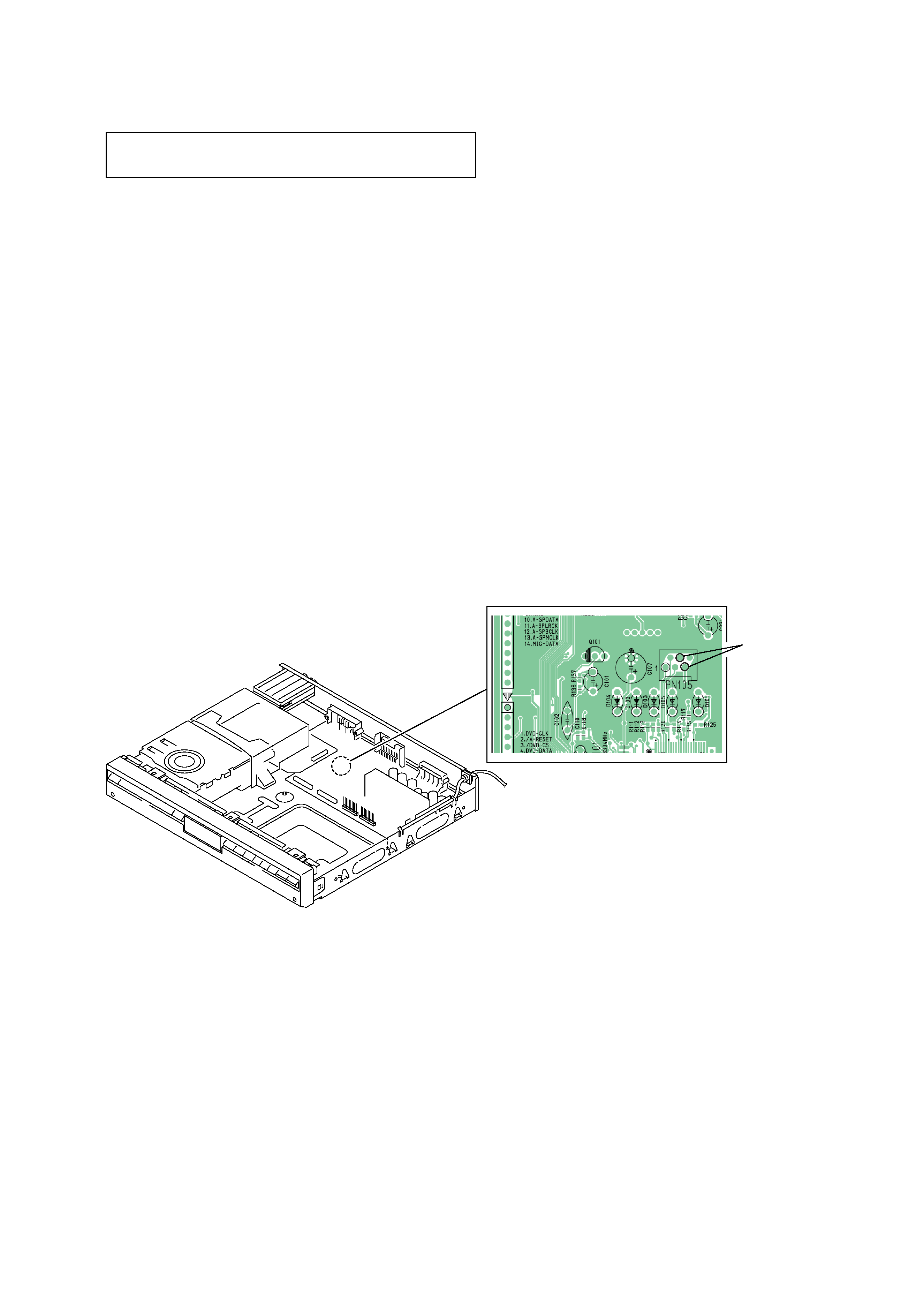
Attention when IC101 (system controller) exchanged.
When IC101 (system controller) is exchanged, discharged C107.
The method of discharging C107, 4 pin and 5 pin of PN105 are
shorted only at the moment.
4
5
short