MICROFILM
AEP Model
UK Model
E Model
Tourist Model
SERVICE MANUAL
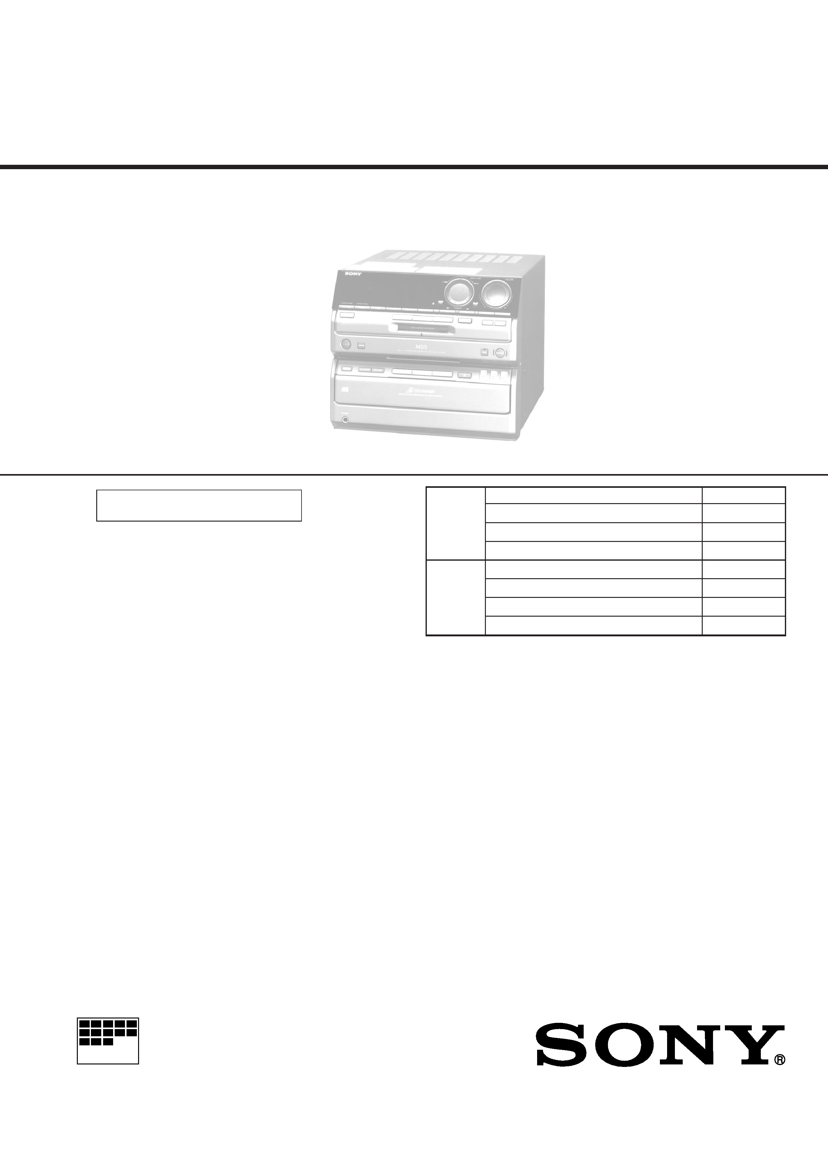
MINI Hi-Fi COMPONENT SYSTEM
HCD-MD5
SPECIFICATIONS
CD player section
System
Compact disc and digital
audio system
Laser
Semiconductor laser
(
=780 nm)
Emission duration:
continuous
Laser output
Max. 44.6 µW*
*This output is the value
measured at a distance of
200 mm from the objective
lens surface on the Optical
Pick-up Block with 7 mm
aperture.
Frequency response
2 Hz 20 kHz (±0.5 dB)
CD OPTICAL DIGITAL OUT
(Square optical connector jack, rear panel)
MD deck section
System
MiniDisc digital audio
system
Laser
Semiconductor laser
(
=780 nm)
Emission duration:
continuous
Laser output
Max. 44.6 µW*
*This output is the value
measured at a distance of
200 mm from the objective
lens surface on the Optical
Pick-up
Block with a
7 mm aperture.
Recording time
74 minutes max. (using
MDW-74)
Sampling frequency
44.1 kHz
Frequency response
5 Hz to 20 kHz
Amplifier section
DIN power output
40 W + 40 W
(6 ohms, at 1 kHz, DIN)
Continuous RMS power output
50 + 50 watts
(6 ohms at 1 kHz, 10%THD)
Peak music power output
700 watts
Music power output
160 watts
Inputs
VIDEO/GAME IN
(phono jacks)
(switchable)
VIDEO IN:
voltage 250 mV,
impedance 47 kilohms
GAME IN:
voltage 450 mV,
impedance 47 kilohms
TAPE IN (phono jacks):
voltage 250mV,
impedance 47 kilohms
Outputs
TAPE OUT (phono jacks):
voltage 250 mV
impedance 1 kilohms
PHONES (stereo phone jack):
accepts headphones of
8 ohms or more.
SPEAKER:
accepts impedance of 6 to
16 ohms.
Model Name Using Similar Mechanism
HCD-W55
CD
CD Mechanism Type
CDM38A-5BD19
Section
Base Unit Name
BU-5BD19
Optical Pick-up Name
KSS-213B/K-N
Model Name Using Similar Mechanism
NEW
MD
MD Mechanism Type
MDM-2FR
Section
Base Unit Name
MBU-2F
Optical Pick-up Name
KMS-210A/J-N
Continued on next page
HCD-MD5 is the amplifier, CD, MD
and tuner section in DHC-MD5.
US and foreign patents licensed from Dolby
Laboratories Licensing Corporation.

2
TABLE OF CONTENTS
1.
SERVICING NOTES .................................................. 3
2.
GENERAL
Index to Parts and Controls ...............................................
5
3.
DISASSEMBLY ............................................................ 7
4.
TEST MODE ................................................................. 14
5.
ELECTRICAL ADJUSTMENTS
MD Section ........................................................................ 20
Tuner Section ..................................................................... 25
CD Section ......................................................................... 26
6.
DIAGRAMS
6-1. Block Diagrams
CD Section ......................................................................... 29
Tuner Section ..................................................................... 31
MD Section ........................................................................ 35
Main Section ...................................................................... 39
6-2. Schematic Diagram Tuner Section
(AEP, G, UK model) .......................................................... 44
6-3. Printed Wiring Board Tuner Section
(AEP, G, UK model) .......................................................... 46
6-4. Printed Wiring Board Tuner Section
(EXCEPT AEP, G, UK model) .......................................... 47
6-5. Schematic Diagram Tuner Section
(EXCEPT AEP, G, UK model) .......................................... 48
6-6. Printed Wiring Board CD Section ............................... 50
6-7. Schematic Diagram CD Section .................................. 53
6-8. Printed Wiring Board MD Section ............................... 56
6-9. Schematic Diagram MD Section .................................. 59
6-10. Schematic Diagram Digital Section ............................ 63
6-11. Printed Wiring Boards Digital Section ........................ 67
6-12. Schematic Diagram Relay Section .............................. 70
6-13. Printed Wiring Board Relay Section ........................... 73
6-14. Printed Wiring Board Main Section ............................ 76
6-15. Schematic Diagram Main Section ............................... 79
6-16. Schematic Diagram Power Section ............................. 83
6-17. Printed Wiring Boards Power Section ......................... 87
6-18. Schematic Diagram Power AMP Section .................... 92
6-19. Printed Wiring Boards Power AMP Section ................ 95
6-20. Schematic Diagram Panel Section ............................... 99
6-21. Printed Wiring Boards Panel Section ........................ 103
6-22. IC Pin Function Description ............................................ 109
7.
EXPLODED VIEWS ................................................. 123
8.
ELECTRICAL PARTS LIST .................................. 132
Tuner section
FM stereo, FM/AM superheterodyne tuner
FM tuner section
Tuning range
Tourist model:
76.0 108.0 MHz (50 kHz step)
Other models:
87.5 108.0 MHz (50 kHz step)
Aerial
FM lead aerial
Aerial terminals
75 ohm unbalanced
Intermediate frequency 10.7 MHz
AM tuner section
Tuning range
German model:
AM:
522 1,611 kHz
(with the interval set at 9 kHz)
AEP, UK models:
MW:
522 1,611 kHz
(with the interval set at 9 kHz)
LW:
144 288 kHz
(with the interval set at 3 kHz)
Tourist model:
AM:
531 1,602 kHz
(with the interval set at 9 kHz)
530 1,710 kHz
(with the interval set at 10 kHz)
Malaysia, Singapore,
Saudi Arabia,
Hong Kong models:
MW:
531 1,602 kHz
(with the interval set at 9 kHz)
530 1,710 kHz
(with the interval set at 10 kHz)
SW:
5.95 17.90 MHz
Aerial
AM loop aerial
External aerial terminals
Intermediate frequency 450 kHz
General
Power requirements
220 230 V AC, 50/60 Hz
(AEP, German model)
110 120 V or 220 240 V AC,
50/60 Hz Adjustable with the
voltage selector (Other model)
Power consumption
85 watts (Tourist model)
130 watts (Other models)
Dimensions
Amplifier/Tuner/MD/CD section:
Approx. 280
× 240 × 360 mm
(11 1/8
× 9 1/2 × 14 1/4 in) (w/h/d) incl.
projecting parts and
controls
(U.K., Hong Kong model)
Approx. 280
× 240 × 350 mm
(11 1/8
× 9 1/2 × 13 7/8 in) (w/h/d) incl.
projecting parts and
controls (Other models)
Mass
Amplifier/Tuner/MD/CD section:
Approx. 9.4 kg
(20 lb 12 oz)
Supplied accessories:
AM loop aerial (1)
Remote RM-S5MD (1)
Sony SUM-3 (NS)
batteries (2)
FM lead aerial (1)
Speaker cords (2)
Design and specifications are subject to change without notice.
3
SECTION 1
SERVICING NOTES
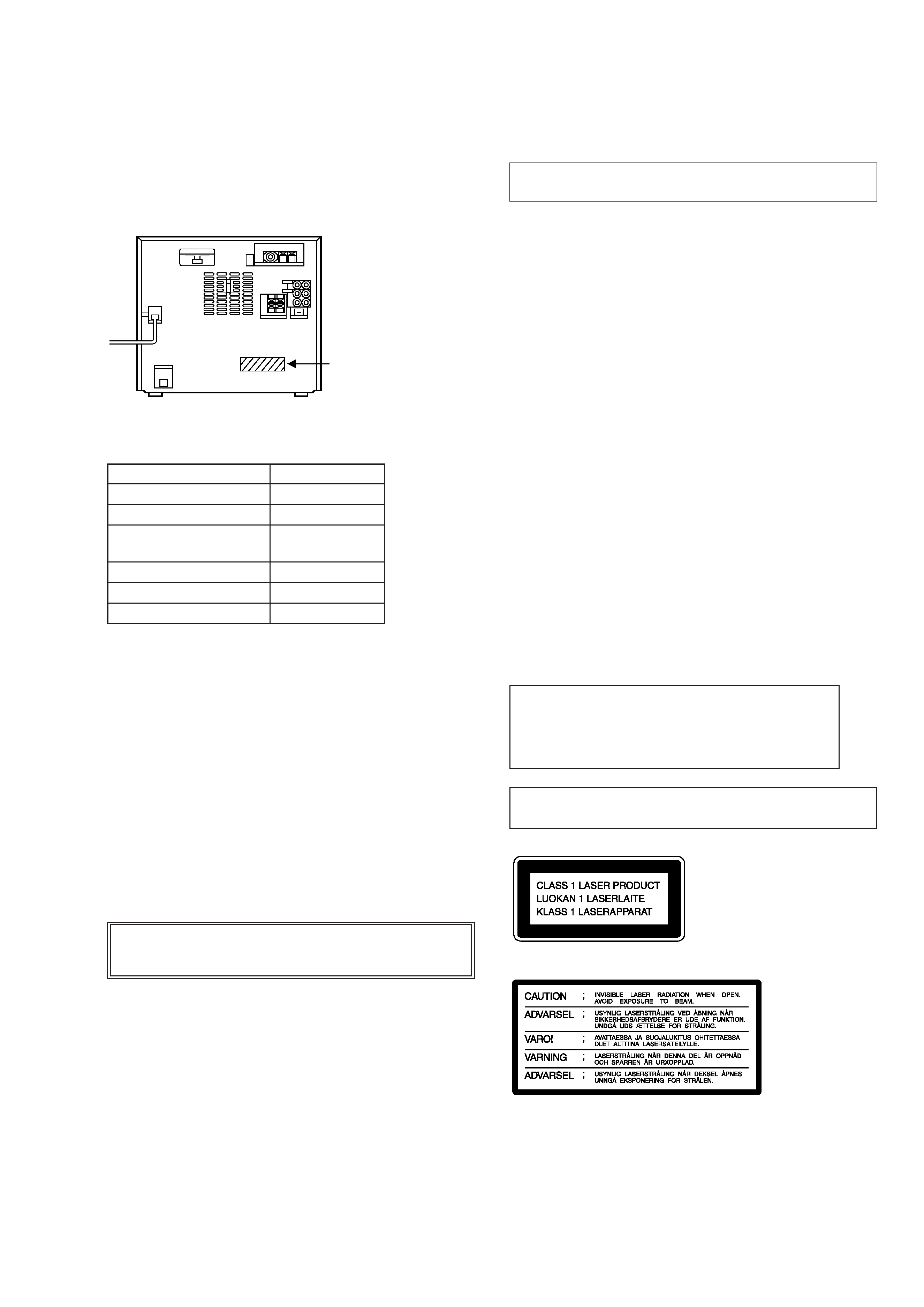
MODEL IDENTIFICATION
-- BACK PANEL --
SAFETY-RELATED COMPONENT WARNING!!
COMPONENTS IDENTIFIED BY MARK
! OR DOTTED
LINE WITH MARK
! ON THE SCHEMATIC DIAGRAMS
AND IN THE PARTS LIST ARE CRITICAL TO SAFE
OPERATION. REPLACE THESE COMPONENTS WITH
SONY PARTS WHOSE PART NUMBERS APPEAR AS
SHOWN IN THIS MANUAL OR IN SUPPLEMENTS PUB-
LISHED BY SONY.
NOTES ON HANDLING THE OPTICAL PICK-UP
BLOCK OR BASE UNIT
The laser diode in the optical pick-up block may suffer electrostatic
break-down because of the potential difference generated by the
charged electrostatic load, etc. on clothing and the human body.
During repair, pay attention to electrostatic break-down and also
use the procedure in the printed matter which is included in the
repair parts.
The flexible board is easily damaged and should be handled with
care.
NOTES ON LASER DIODE EMISSION CHECK
The laser beam on this model is concentrated so as to be focused on
the disc reflective surface by the objective lens in the optical pick-
up block. Therefore, when checking the laser diode emission, ob-
serve from more than 30 cm away from the objective lens.
Notes on chip component replacement
· Never reuse a disconnected chip component.
· Notice that the minus side of a tantalum capacitor may be dam-
aged by heat.
Flexible Circuit Board Repairing
· Keep the temperature of soldering iron around 270 °C during re-
pairing.
· Do not touch the soldering iron on the same conductor of the
circuit board (within 3 times).
· Be careful not to apply force on the conductor when soldering or
unsoldering.
CAUTION
Use of controls or adjustments or performance of pro-
cedures other than those specified herein may result in
hazardous radiation exposure.
Laser component in this product is capable of emitting radia-
tion exceding the limit for Class 1.
This appliance is classified as a
CLASS 1 LASER product.
The CLASS 1 LASER PROD-
UCT MARKING is located on the
rear exterior.
This caution label
is located inside
the unit.
Note:
Be sure to connect all wires (including FFC) in the MD
section before applying power or ICs may be damaged.
MODEL
PARTS No
AEP model
4-984-208-1
UK model
4-984-208-2
Saudi Arabia, Singapore,
4-984-208-3
Malaysia model
German model
4-984-208-4
Hong Kong model
4-984-208-5
Tourist model
4-984-208-7
Parts No.
4
COLD START METHOD
While pressing the POWER key, insert the AC plug cord into the
AC outlet. Cold start will be set.
Note :
As cold start will erase all the preset contents etc., do not set it in
normal operations.
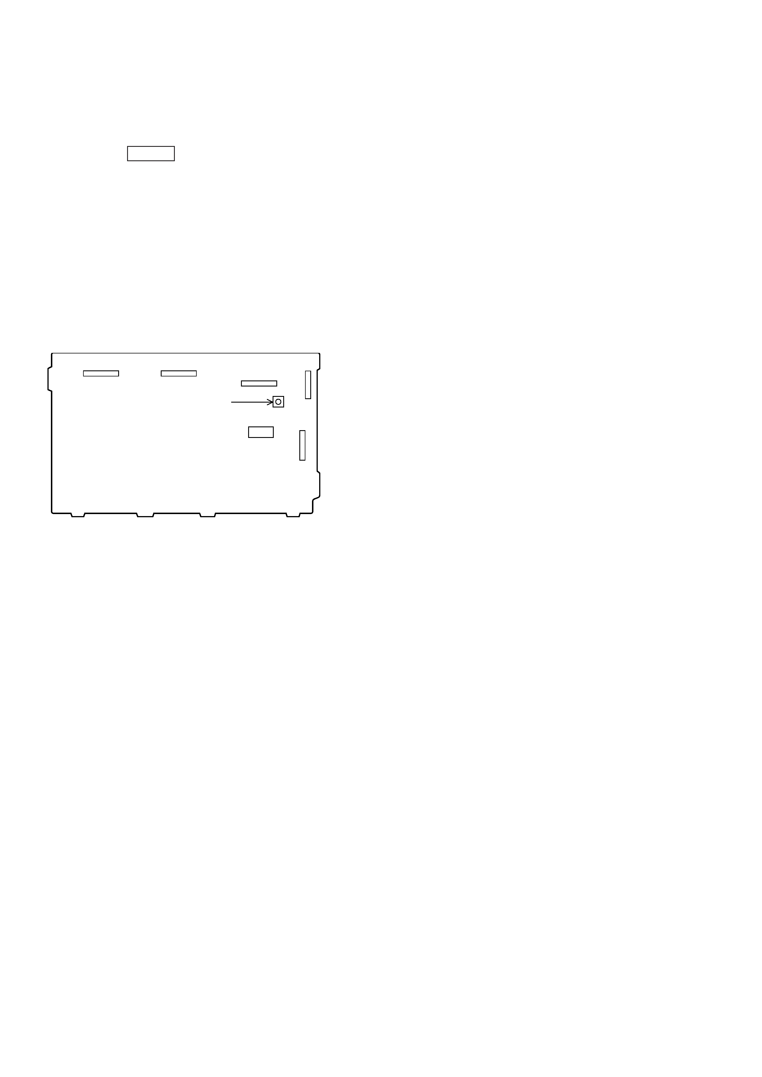
FORCED RESET SWITCH
The switch on the power board (S101) is the forced reset switch for
IC201.
Press it for about one second after turning on the power after disas-
sembling and assembling the unit again.
· Parts Location
[POWER BOARD] -- Component side --
CN803
CN802
IC821
IC102
S101
RESET
Switch
CN807
CN808
5
SECTION 2
GENERAL
This section is extracted
from instruction manual.
Fr
ont
P
anel
Inde
x
to
P
a
rts
and
Contr
ols
1
TUNER/BAND
button
2
PLA
Y
MODE/TUNING
MODE
b
utton
3
REPEA
T/STEREO/MONO
b
utton
4
1/ALL
DISCS
button
5
DISPLA
Y
b
utton
6
TIMER
SET
button
7
TIMER
SELECT
button
8
EDIT/NO
button
9
MUL
TI
JOG
control
0
ENTER/YES
button
!¡
º
/,
(fast
backward/fast
forward)
/
CUSOR
button
!TM
VOLUME
control
!£
CHARACTER
button
!¢
PRESET
EQ
button
!
SYSTEM
POWER
switch
!§
FUNCTION
button
!¶
MD
control
button
·
(MD
play)
button
(MD
pause)
button
(MD
stop)
button
§
(MD
EJECT)
button
MD
slot
!·
DBFB
button
!ª
GROOVE
button
@º
CD
SYNC
button
@¡
r
REC
button
@TM
PHONES
jack
@£
LOOP
button
@¢
EX-CHANGE
button
@
DISC
SKIP
button
@§
CD
control
button
·
(CD
play)
button
(CD
pause)
button
(CD
stop)
button
§
(CD
EJECT)
button
@¶
DISC
1-3
buttons
@·
DISC
TRA
Y
12
3
5
6
7
4
6
EXCEPT
AEP,
German,
UK
mode
l
AEP,
German,
UK
model
8
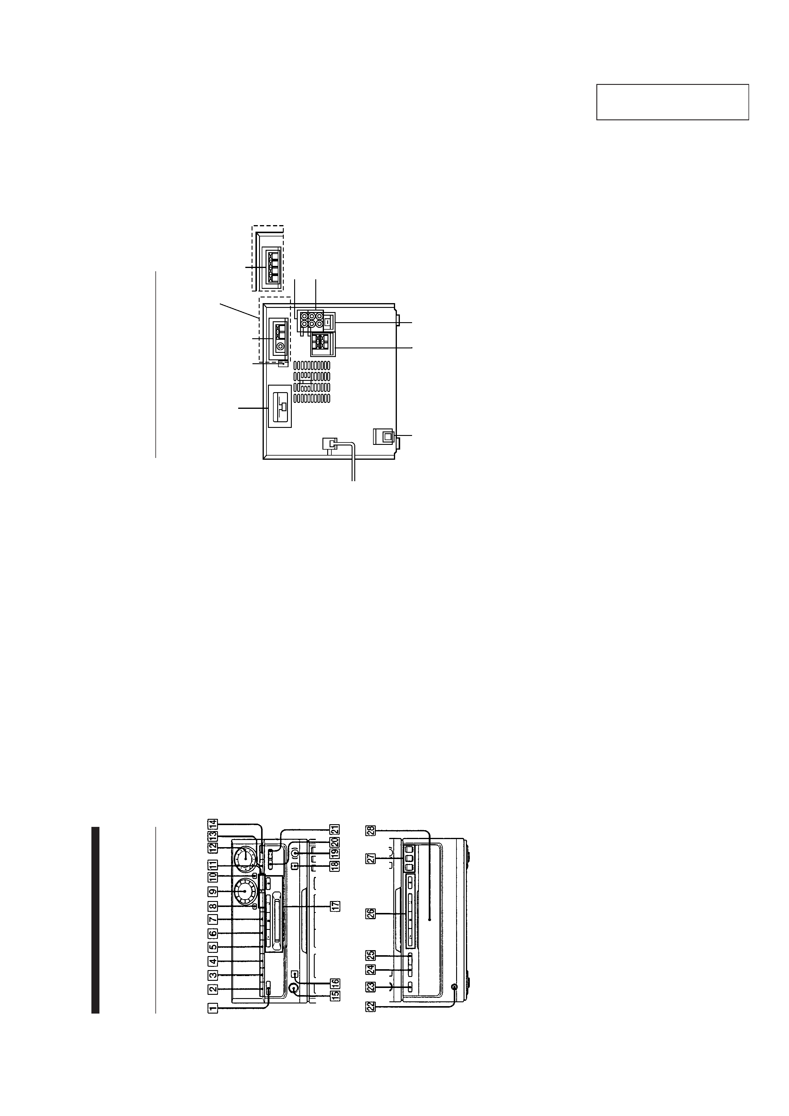
Rear
P
anel
1
CD
OPTICAL
DIGIT
AL
OUT
jac
k
2
SPEAKER
connectors
3
AU
BUS
connector
4
T
APE
input/output
jac
k
5
VIDEO
GAME/VCR
connectors
6
Aerial
terminals
7
SIGNAL
Ground
terminal
8
V
O
LT
A
GE
SELECT
OR
(Mala
ysia,
singapore
,Saudi
Ar
abia,
Hong
K
ong,
T
our
ist
model)