HCD-MC1
US Model
E Model
SERVICE MANUAL
MINI HI-FI COMPONENT SYSTEM
Manufactured under license from Dolby Laboratories
Licensing Corporation.
"DOLBY" and the double-D symbol
aare trademarks
of Dolby Laboratories Licensing Corporation.
-- Continued on next page --
SPECIFICATIONS
· This set is the tuner, deck, CD
and amplifier section in MHC-MC1.
Model Name Using Similar Mechanism HCD-F150/FR10
CD Mechanism Type
CDM-46B1
Optical Pick-up Name
KSS-213BA/F-NP
Model Name Using Similar Mechanism HCD-DR8AV
Tape Transport Mechanism Type
TCM-230AWR2/230PWR2
CD
Section
Tape deck
Section
Sony Corporation
Home Audio Company
Published by Sony Engineering Corporation
9-928-899-12
2001J1600-1
© 2001.10
Amplifier section
U.S.A models:
AUDIO POWER SPECIFICATIONS
POWER OUTPUT AND TOTAL HARMONIC DISTORTION:
With 8
loads both channels driven, from 70 20,000 Hz; rated 80 W per
channel minimum RMS power, with no more than 0.9% toral harmonic
distortion from 250 mW to read output.
Continuous RMS power output
80 + 80 W(8
at 1kHz, 10% THD)
Tortal harmonic distortion
less than 0.09%(8
at 1kHz, 40W)
Inputs
VIDEO/MD IN (phono jack):
voltage 250mV/450mV,
impedance 47k
Outputs
VIDEO/MD OUT (phono jack):
voltage 250mV,
impedance 1k
PHONES (stereo phone jacks):
accepts headphones of 8
or more
SPEAKER : accepts impedance of 8 to 16
REAR SPEAKER :
accepts impedance of 16
SUPER WOOFER :
Voltage 1V, impedance 1k
CD player section
System
Compact disc and digital audio system
Laser
Semiconductor laser (
=780mm)
Emission duration:
continuous
Laser output
Max. 44.6
µW*
*This output is the value measured at a distance of
200 mm from the objective lens surface on the
Optical Pick-up Block with 7 mm aperture.
Frequency response
2Hz 20kHz (
±0.5dB)
Wavelength
780 790nm
Signal-to-noise retio
More than 90dB
Dynamic range
More than 90dB
CD OPTICAL DIGITAL OUT
(Square optical connector jack, rear panel)
Output Level
18dBm
Tape player section
Recording system
4-track 2-channel stereo
Frequency response (DOLBY NR OFF)
40 13,000Hz (
±3dB),
using Sony TYPE I
cassette
40 14,000Hz (
±3dB),
using Sony TYPE II
cassette
Tuner section
FM stereo, FM/AM superheterodyne tuner
FM tuner section
Tuning range
87.5 108.0MHz
Antenna
FM lead antenna
Antenna terminals
75
unbalanced
Intermediate frequency 10.7MHz
Ver 1.1 2001. 10

-- 2 --
AM tuner section
Tuning renge
530 1,710kHz
(with the interval set at 10kHz)
531 1,710kHz
(with the interval set at 9kHz)
Antenna
AM loop antenna
Antenna terminals
External antenna terminal
Intermediate frequency 450kHz
General
Power requirements
US model : 120V AC, 60Hz
E model
: 110 - 120V or 220 - 240V AC, 50/60Hz
Power consumption
US model : 200W
E model
: 250W
Dimensions (w/h/d)
Apprex. 280
× 373 × 437mm
(111/8
× 143/4 × 171/4 in)
Mass
Apprex. 11.2kg (24 lb 11 oz)
Supplied accessories:
AM loop antenna (1)
Remote RM-SF150 (1)
Batteries (2)
FM lead antenna (1)
Speaker cords (2)
Front speaker pads (8)
Design and specifications are subject to change without notice.
This appliance is classified as a CLASS 1 LASER product. The
CLASS 1 LASER PRODUCT MARKING is located on the rear
exterior.
The following caution label is located inside the unit.
Laser component in this product is capable
of emitting radiation exceeding the limit for
Class 1.
CAUTION
Use of controls or adjustments or performance of procedures
other than those specified herein may result in hazardous radiation
exposure.
SAFETY-RELATED COMPONENT WARNING!!
COMPONENTS IDENTIFIED BY MARK
! OR DOTTED LINE WITH
MARK
! ON THE SCHEMATIC DIAGRAMS AND IN THE PARTS
LIST ARE CRITICAL TO SAFE OPERATION. REPLACE THESE
COMPONENTS WITH SONY PARTS WHOSE PART NUMBERS
APPEAR AS SHOWN IN THIS MANUAL OR IN SUPPLEMENTS
PUBLISHED BY SONY.
SAFETY CHECK-OUT
(US model only)
After correcting the original service problem, perform the
following safety checks before releasing the set to the customer:
Check the antenna terminals, metal trim, "metallized" knobs, screws,
and all other exposed metal parts for AC leakage. Check leakage as
described below.
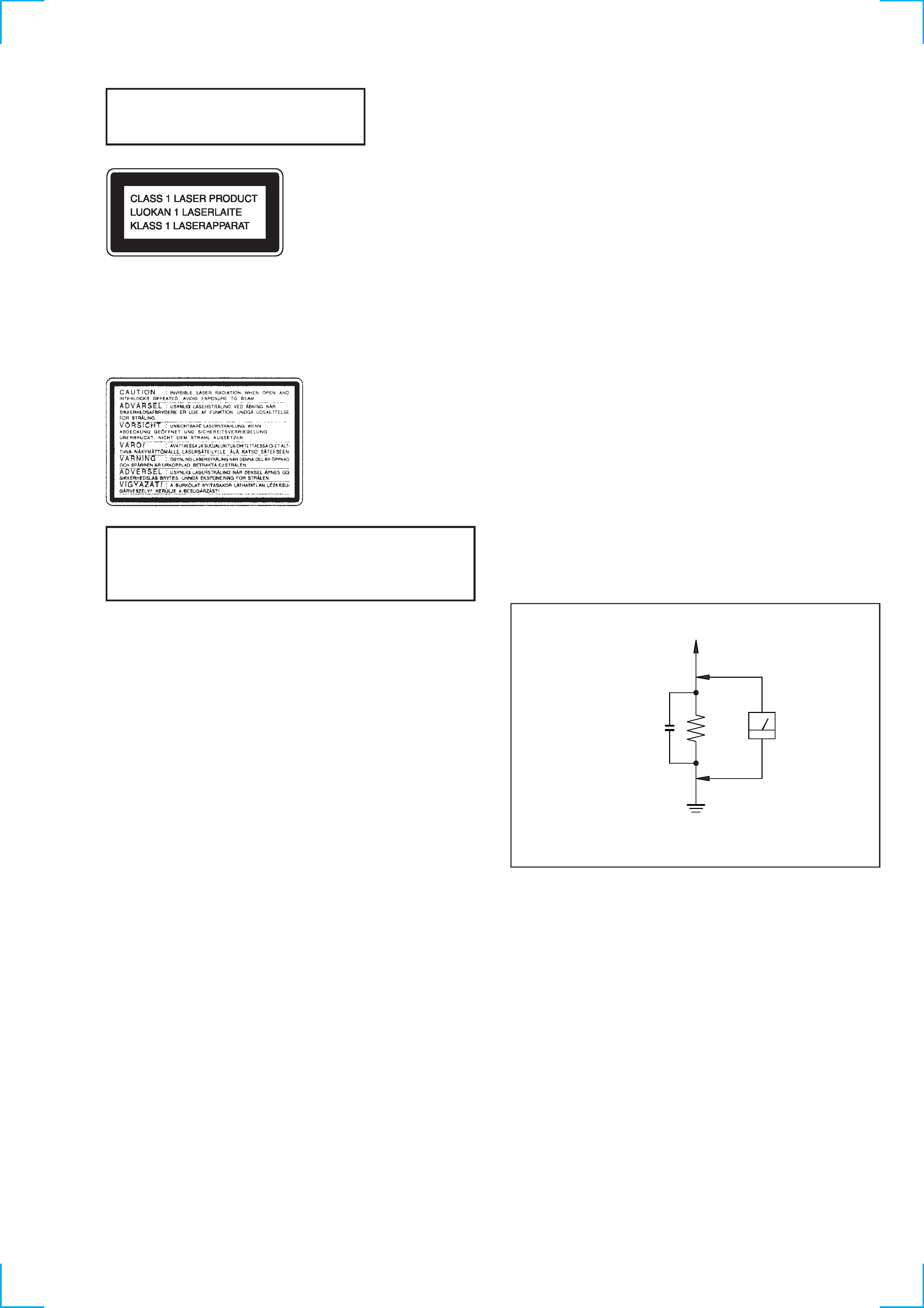
LEAKAGE
The AC leakage from any exposed metal part to earth ground
and from all exposed metal parts to any exposed metal part having
a return to chassis, must not exceed 0.5 mA (500 microampers).
Leakage current can be measured by any one of three methods.
1.
A commercial leakage tester, such as the Simpson 229 or RCA
WT-540A. Follow the manufacturers' instructions to use these
instruments.
2.
A battery-operated AC milliammeter. The Data Precision 245
digital multimeter is suitable for this job.
3.
Measuring the voltage drop across a resistor by means of a
VOM or battery-operated AC voltmeter. The "limit" indication
is 0.75 V, so analog meters must have an accurate low-voltage
scale. The Simpson 250 and Sanwa SH-63Trd are examples of
a passive VOM that is suitable. Nearly all battery operated
digital multimeters that have a 2V AC range are suitable. (See
Fig. A)
Earth Ground
AC
voltmeter
(0.75V)
1.5k
0.15
µF
Fig. A. Using an AC voltmeter to check AC leakage.
To Exposed Metal
Parts on Set
-- 3 --

-- 4 --
TABLE OF CONTENTS
1. GENERAL
FRONT PANEL ····································································· 5
REAR PANEL ········································································ 6
2. DISASSEMBLY ······························································· 8
3. TEST MODE ··································································· 16
4. MECHANICAL ADJUSTMENTS ···························· 18
5. ELECTRICAL ADJUSTMENTS
Deck Section ········································································ 21
CD Section ··········································································· 24
6. DIAGRAMS
6-1.
Block Diagram CD Section ············································ 27
Block Diagram
Main Section ········································ 29
Block Diagram Audio Section ········································ 31
6-2.
Circuit Boards Location ··················································· 33
6-3.
Printed Wiring Board BD Section ·································· 35
6-4.
Schematic Diagram BD Section ····································· 37
6-5.
Printed Wiring Board CD Motor Section ······················· 39
6-6.
Schematic Diagram CD Motor Section ·························· 41
6-7.
Printed Wiring Board Audio Section ······························ 43
6-8.
Schematic Diagram Audio Section ································· 45
6-9.
Printed Wiring Board Leaf SW Section ························· 47
6-10. Schematic Diagram Leaf SW Section ···························· 49
6-11. Printed Wiring Board Main Section ······························· 51
6-12. Schematic Diagram Main (1/5) Section ························· 53
6-13. Schematic Diagram Main (2/5) Section ························· 55
6-14. Schematic Diagram Main (3/5) Section ························· 57
6-15. Schematic Diagram Main (4/5) Section ························· 59
6-16. Schematic Diagram Main (5/5) Section ························· 61
6-17. Printed Wiring Board Panel Section ······························· 63
6-18. Schematic Diagram Panel Section ································· 65
6-19. Printed Wiring Board Power Section ····························· 67
6-20. Schematic Diagram Power Section ································ 69
6-21. Waveforms ········································································ 71
6-22. IC Pin Function Description ············································· 72
6-23. IC Block Diagrams ··························································· 80
7. EXPLODED VIEWS ····················································· 81
8. ELECTRICAL PARTS LIST ····································· 89
SERVICING NOTES
The laser diode in the optical pick-up block may suffer electrostatic
break-down because of the potential difference generated by the
charged electrostatic load, etc. on clothing and the human body.
During repair, pay attention to electrostatic break-down and also
use the procedure in the printed matter which is included in the
repair parts.
The flexible board is easily damaged and should be handled with
care.
NOTES ON LASER DIODE EMISSION CHECK
The laser beam on this model is concentrated so as to be focused on
the disc reflective surface by the objective lens in the optical pick-
up block. Therefore, when checking the laser diode emission, observe
from more than 30 cm away from the objective lens.
LASER DIODE AND FOCUS SEARCH OPERATION
CHECK
Carry out the "S curve check" in "CD section adjustment" and check
that the S curve waveform is output repeatedly.
NOTES ON HANDLING THE OPTICAL PICK-UP
BLOCK OR BASE UNIT
Notes on chip component replacement
· Never reuse a disconnected chip component.
· Notice that the minus side of a tantalum capacitor may be damaged
by heat.
Flexible Circuit Board Repairing
· Keep the temperature of the soldering iron around 270 °C during
repairing.
· Do not touch the soldering iron on the same conductor of the
circuit board (within 3 times).
· Be careful not to apply force on the conductor when soldering or
unsoldering.
-- 5 --
SECTION 1
GENERAL
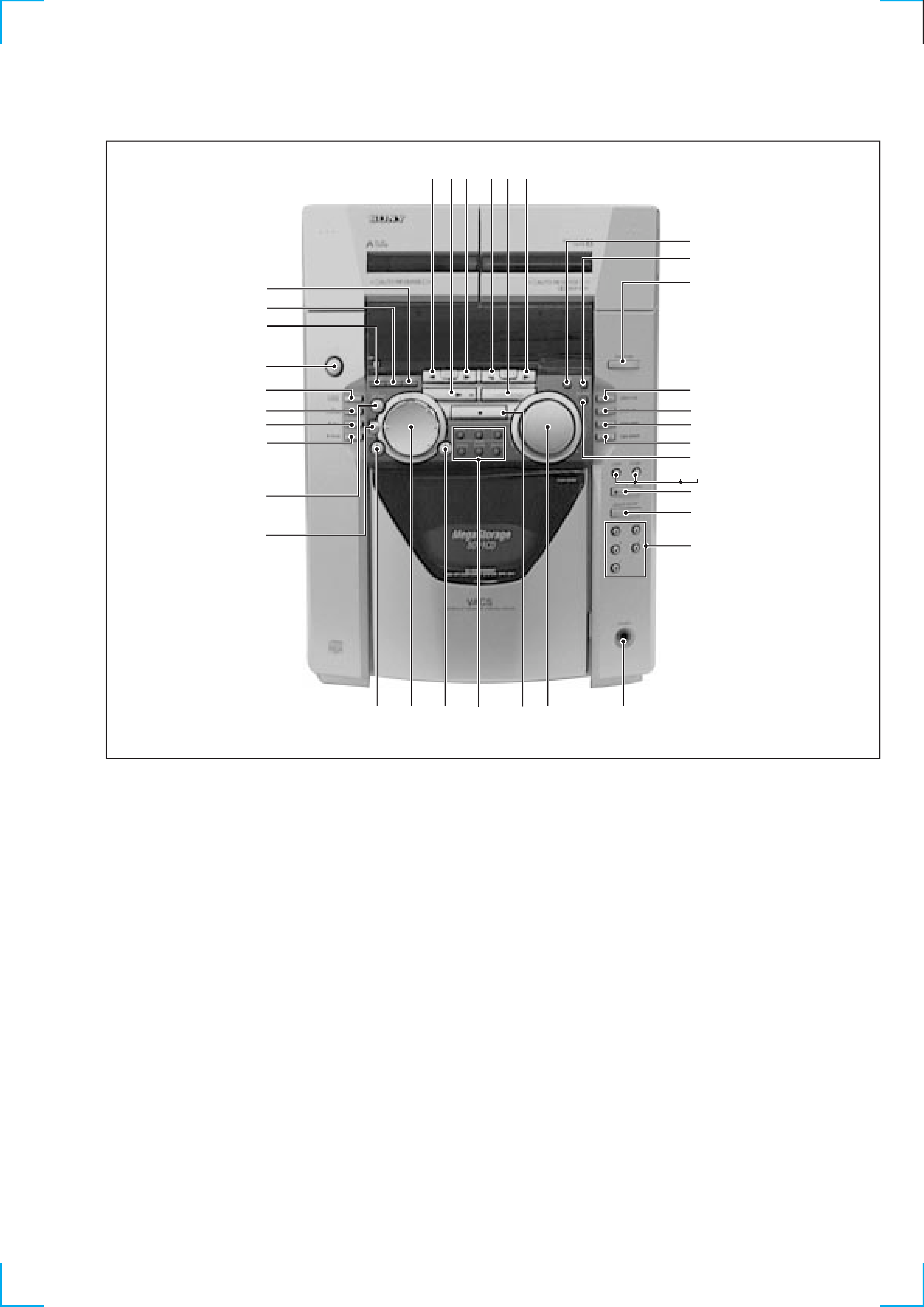
FRONT PANEL
57
69
80
!¡
!TM
!£
!¢
!¶
!·
@º
!ª
!
@¡
@TM
!§
#§
2
3
4
#£
#TM
#¡
#
1
#¢
@£
@¢
@
@ª
@·
#º
@§
@¶
1 1/u button
2 DISPLAY/MEMO button
3 CLOCK TIMER SET button
4 TIMER SELECT button
5 TAPE A ª button
6 CD fl button
7 TAPE A · button
8 TAPE B ª button
9 TUNER/BAND button
0 TAPE B · button
!¡ SUR button
!TM DBFB button
!£ FUNCTION button
!¢ CONTINUE/DIRECTION button
! PROGRAM/DOLBY-NR button
!§ SHUFFLE/STEREO/MONO button
!¶ REPEAT/TUNER MEMORY button
!· GROOVE button
!ª LOOP button
@º FLASH button
@¡ CD PLUS ONE button
@TM GROUP ENTRY button
@£ Numeric buttons
@¢ PHONES jack
@ VOLUME Knob
@§ STOP button
@¶ INPUT, SCAN, SEARCH, CHECK,
CLEAR, DELETE buttons
@· CD )+, + button
@ª SELECTOR button
#º CD -0, = button
#¡ ENTER button
#TM FILE SELECT button
#£ P PAUSE button
#¢ r REC button
# CD SYNCHRO button
#§ HI-SPEED DUBBING button