SERVICE MANUAL
COMPACT DISC DECK RECEIVER
US Model
Canadian Model
E Model
Australian Model
HCD-EP30
AEP Model
UK Model
HCD-EP30/EP40
SPECIFICATIONS
HCD-EP30/EP40
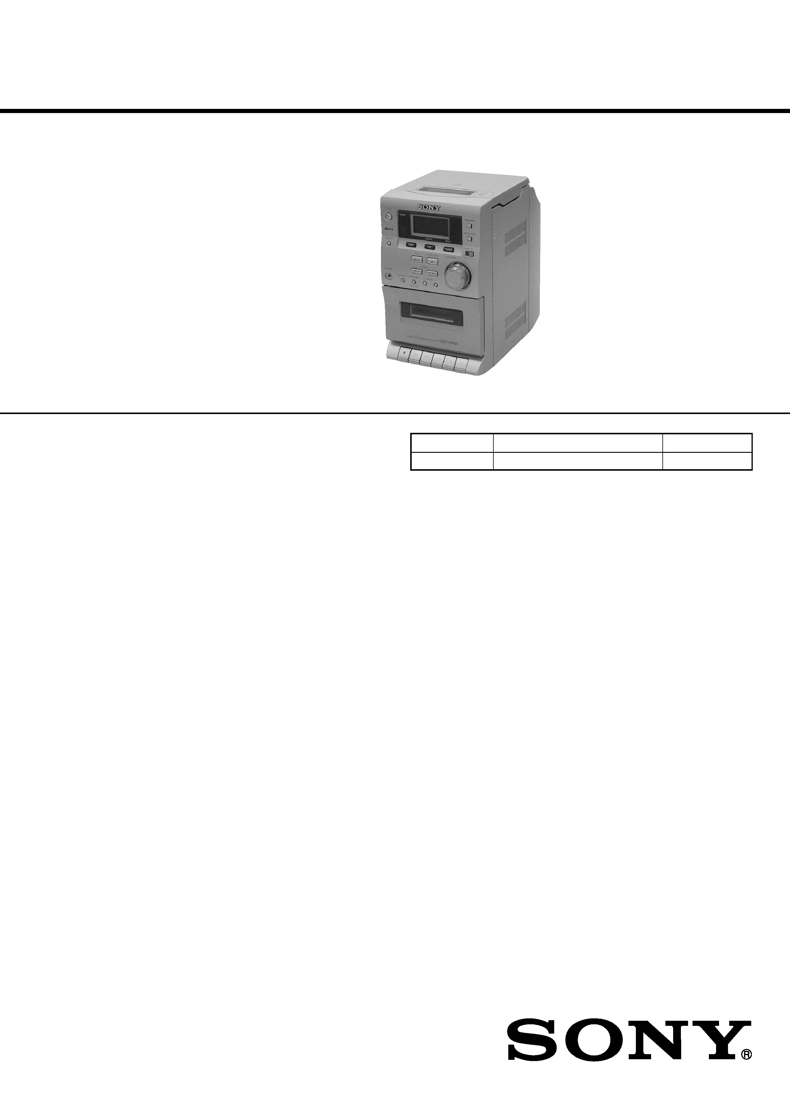
Photo: HCD-EP40
Ver 1.0 2001.04
HCD-EP30/EP40 are the amplifier, CD
player, tape deck and tuner section in
CMT-EP30/EP40.
CD Section
CD Mechanism Type
CS-21SC-1280
TAPE Section
Tape Transport Mechanism Type
TCM125-2
9-873-867-11
Sony Corporation
2001D0500-1
Home Audio Company
C
2001.4
Shinagawa Tec Service Manual Production Group
Amplifier section
AUDIO POWER SPECIFICATIONS:
(US model only)
POWER OUTPUT AND TOTAL
HARMONIC DISTORTION:
with 4
loads both channels driven, from 120
- 10,000 Hz; rates 5 W per channel minimum
RMS power, with no more than 10% total
harmonic distortion from 250 mW to rated
output.
Canadian model:
Continuous RMS power output (reference)
5 + 5 W
(4
at 1 kHz, 10% THD)
AEP, UK models:
DIN power output (rated) 4.5 + 4.5 W
(4
at 1 kHz, DIN)
Continuous RMS power output (reference)
5 + 5 W
(4
at 1 kHz, 10% THD)
Music power output (reference)
13 + 13 W
Other models:
The following measured at AC 230 V, 50/60 Hz
DIN power output (rated) 4.5 + 4.5 W
(4
at 1 kHz, DIN)
Continuous RMS power output (reference)
5 + 5 W
(4
at 1 kHz, 10% THD)
Outputs
PHONES:
Accepts headphones of
(stereo mini jack)
8
or more
SPEAKER:
Accepts impedance of 4 to
16
CD player section
System
Compact disc and digital
audio system
Laser
Semiconductor laser
(
=780 nm)
Emission duration:
continuous
Frequency response
20 Hz - 20 kHz (
±0.5 dB)
Tape player section
Recording system
4-track 2-channel stereo
Frequency response
50 - 13 000 Hz (
±3 dB),
using Sony TYPE I
cassette
Tuner section
FM stereo, FM/AM superheterodyne tuner
FM tuner section
Tuning range
87.5 - 108.0 MHz
Antenna
FM lead antenna
Intermediate frequency
10.7 MHz
AM tuner section
Tuning range
Pan-American model:
530 - 1 710 kHz
(with the interval set at
10 kHz)
531 - 1 602 kHz
(with the interval set at
9 kHz)
European model:
531 -1 602 kHz
(with the interval set at
9 kHz)
Other models:
531 - 1 602 kHz
(with the interval set at
9 kHz)
530 - 1 710 kHz
(with the interval set at
10 kHz)
Antenna
Built-in ferrite bar antenna
Intermediate frequency
450 kHz
General
Power requirements
US, Canadian models:
120 V AC, 60 Hz
AEP, UK models:
230 V AC, 50/60 Hz
Australian model:
230 V AC, 50/60 Hz
Mexican model:
120 V AC, 60 Hz
Argentine model:
220 V AC, 50/60 Hz
Taiwan model:
110 V AC, 60 Hz
Other models:
230 V AC, 50/60 Hz
Power consumption
US model:
25 W
Canadian model:
25 W
AEP, UK models:
30 W
0.9 W (in the standby
mode)
Other models:
30 W
Dimensions (w/h/d):
Approx. 145
× 238 × 238 mm
Mass:
Approx. 2.8 kg
Design and specifications are subject to change
without notice.

2
HCD-EP30/EP40
TABLE OF CONTENTS
1.
SERVICING NOTES ................................................ 4
2.
GENERAL ................................................................... 5
3.
DISASSEMBLY
3-1. Disassembly Flow ...........................................................
7
3-2. Front Panel Section .........................................................
8
3-3. MAIN Board ...................................................................
8
3-4. CD Cabinet Section .........................................................
9
3-5. CD Mechanism Deck (CS-21SC-1280) .........................
9
3-6. Tape Mechanism Deck (TCM125-2) .............................. 10
3-7. Cassette Lid ..................................................................... 10
4.
MECHANICAL ADJUSTMENTS ....................... 11
5.
ELECTRICAL ADJUSTMENTS ......................... 11
6.
DIAGRAMS
6-1. Note for Printed Wiring Boards and
Schematic Diagrams ....................................................... 15
6-2. Schematic Diagram MAIN Board (1/2) .................. 16
6-3. Schematic Diagram
MAIN (2/2)/HEADPHONE Boards ......................... 17
6-4. Printed Wiring Boards
MAIN/HEADPHONE Boards .................................. 18
6-5. Printed Wiring Board CASSETTE Board ............... 19
6-6. Schematic Diagram CASSETTE Board .................. 19
6-7. Printed Wiring Board DISPLAY Board .................. 20
6-8. Schematic Diagram DISPLAY Board ..................... 21
6-9. Schematic Diagram POWER Board ........................ 22
6-10. Printed Wiring Board POWER Board ..................... 23
6-11. IC Pin Function Description ........................................... 25
7.
EXPLODED VIEWS
7-1. Cabinet Section ............................................................... 26
7-2. Front Panel Section-1 ...................................................... 27
7-3. Front Panel Section-2 ...................................................... 28
7-4. CD Cabinet Section ......................................................... 29
8.
ELECTRICAL PARTS LIST ............................... 30
3
HCD-EP30/EP40
Notes on chip component replacement
· Never reuse a disconnected chip component.
· Notice that the minus side of a tantalum capacitor may be dam-
aged by heat.
Flexible Circuit Board Repairing
· Keep the temperature of the soldering iron around 270 °C dur-
ing repairing.
· Do not touch the soldering iron on the same conductor of the
circuit board (within 3 times).
· Be careful not to apply force on the conductor when soldering
or unsoldering.
CAUTION
Use of controls or adjustments or performance of procedures
other than those specified herein may result in hazardous ra-
diation exposure.
SAFETY CHECK-OUT
After correcting the original service problem, perform the follow-
ing safety check before releasing the set to the customer:
Check the antenna terminals, metal trim, "metallized" knobs,
screws, and all other exposed metal parts for AC leakage.
Check leakage as described below.
LEAKAGE TEST
The AC leakage from any exposed metal part to earth ground and
from all exposed metal parts to any exposed metal part having a
return to chassis, must not exceed 0.5 mA (500 microamperes.).
Leakage current can be measured by any one of three methods.
1. A commercial leakage tester, such as the Simpson 229 or RCA
WT-540A. Follow the manufacturers' instructions to use these
instruments.
2. A battery-operated AC milliammeter. The Data Precision 245
digital multimeter is suitable for this job.
3. Measuring the voltage drop across a resistor by means of a
VOM or battery-operated AC voltmeter. The "limit" indica-
tion is 0.75 V, so analog meters must have an accurate low-
voltage scale. The Simpson 250 and Sanwa SH-63Trd are ex-
amples of a passive VOM that is suitable. Nearly all battery
operated digital multimeters that have a 2 V AC range are suit-
able. (See Fig. A)
Fig. A.
Using an AC voltmeter to check AC leakage.
1.5 k
0.15
µF
AC
voltmeter
(0.75 V)
To Exposed Metal
Parts on Set
Earth Ground
ATTENTION AU COMPOSANT AYANT RAPPORT
À LA SÉCURITÉ!
LES COMPOSANTS IDENTIFIÉS PAR UNE MARQUE 0
SUR LES DIAGRAMMES SCHÉMATIQUES ET LA LISTE
DES PIÈCES SONT CRITIQUES POUR LA SÉCURITÉ
DE FONCTIONNEMENT. NE REMPLACER CES COM-
POSANTS QUE PAR DES PIÈCES SONY DONT LES
NUMÉROS SONT DONNÉS DANS CE MANUEL OU
DANS LES SUPPLÉMENTS PUBLIÉS PAR SONY.
SAFETY-RELATED COMPONENT WARNING!!
COMPONENTS IDENTIFIED BY MARK 0 OR DOTTED
LINE WITH MARK 0 ON THE SCHEMATIC DIAGRAMS
AND IN THE PARTS LIST ARE CRITICAL TO SAFE
OPERATION. REPLACE THESE COMPONENTS WITH
SONY PARTS WHOSE PART NUMBERS APPEAR AS
SHOWN IN THIS MANUAL OR IN SUPPLEMENTS PUB-
LISHED BY SONY.
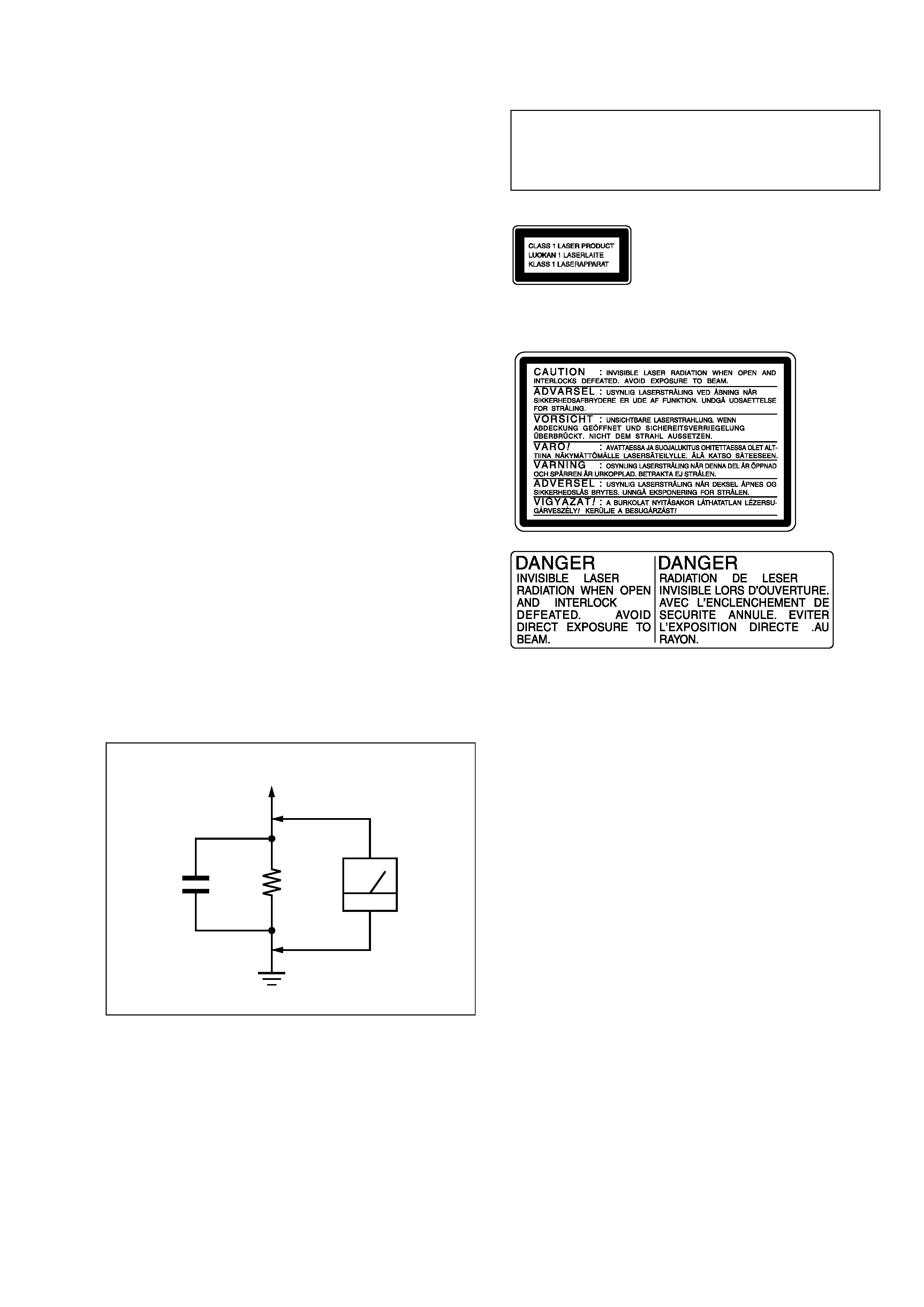
The following caution label is located inside the unit.
This appliance is classified as
a CLASS 1 LASER product.
The CLASS 1 LASER
PRODUCT MARKING is
located on the rear exterior.
4
HCD-EP30/EP40
NOTES ON HANDLING THE OPTICAL PICK-UP
BLOCK OR BASE UNIT
The laser diode in the optical pick-up block may suffer electro-
static break-down because of the potential difference generated
by the charged electrostatic load, etc. on clothing and the human
body.
During repair, pay attention to electrostatic break-down and also
use the procedure in the printed matter which is included in the
repair parts.
The flexible board is easily damaged and should be handled with
care.
NOTES ON LASER DIODE EMISSION CHECK
The laser beam on this model is concentrated so as to be focused
on the disc reflective surface by the objective lens in the optical
pick-up block. Therefore, when checking the laser diode emis-
sion, observe from more than 30 cm away from the objective lens.
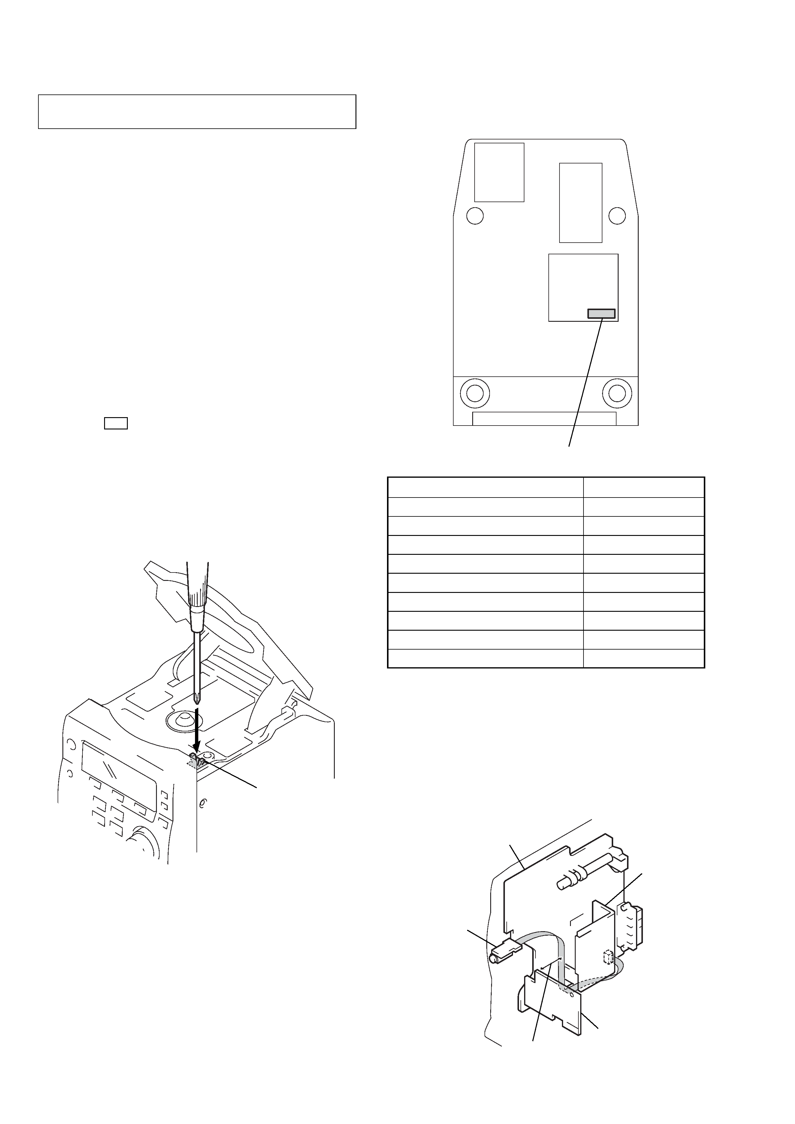
LASER DIODE AND FOCUS SEARCH OPERATION
CHECK
1. Press the I/1 button to the power ON with no disc inserted
and press the [CD] button.
2. Open the lid for CD.
3. Turn on SW600 as following figure.
4. Confirm the laser diode emission while observing the object-
ing lens. When there is no emission, Auto Power Control cir-
cuit or Optical Pick-up is broken.
Objective lens moves up and down five times for the focus
search.
SECTION 1
SERVICING NOTES
· MODEL IDENTIFICATION
Bottom View
MODEL
PART No.
EP30: AEP and UK models
4-235-167-0[]
US and Canadian models
4-235-169-0[]
Singapore model
4-235-170-0[]
Australian model
4-235-171-0[]
Taiwan model
4-235-172-0[]
Mexican model
4-235-173-0[]
Argentina model
4-235-174-0[]
EP40: AEP and UK models
4-235-175-0[]
Saudi Arabia model
4-236-316-0[]
TO PREVENT `TAPE OSCILLATION SOUND AT VOLUME'
MAXIMUM SETTING (W/O TAPE)
Headphone wire dressing:
a.) Draw the wire from Main board to Headphone Jack board along
the bottom side of heatsink.
b.) The wire must be kept away from the top side of Cassette board
at least 30 mm.
SW600
PART No.
CASSETTE board
MAIN board
HEADPHONE
board
at least 30 mm
heatsink
5
HCD-EP30/EP40
SECTION 2
GENERAL
This section is extracted from
instruction manual.
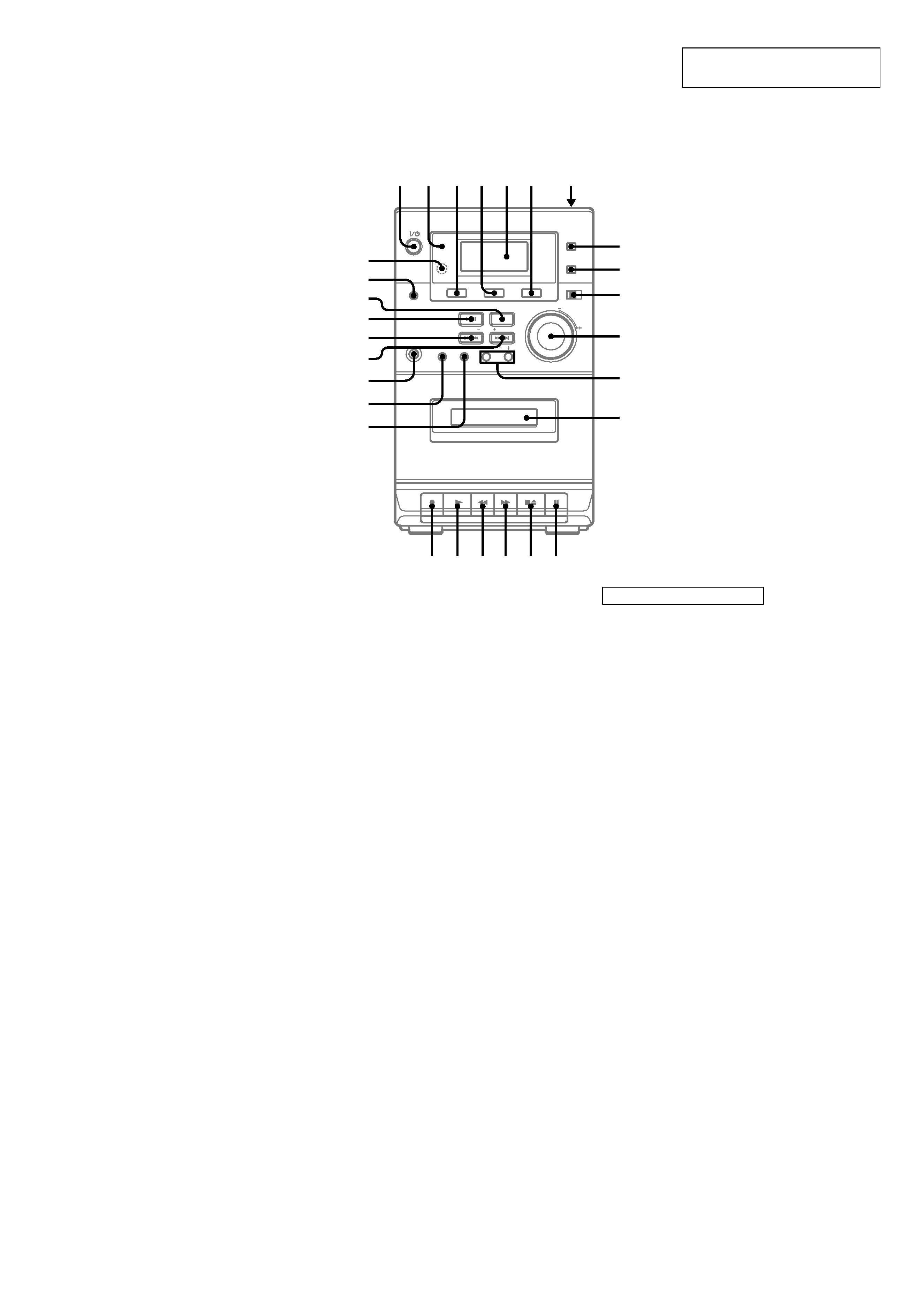
LOCATION OF CONTROLS
Front Panel
Cassette compartment qd (12)
CD 4 (8, 9, 13, 15)
Display Window 5 (9, 18)
ENTER/PGM w; (7, 8, 9, 10, 12,
15)
ISS 0 (13)
MEGA BASS 8 (14)
MONO STEREO 0 (11)
MUSIC MENU 9 (14)
PHONES jack ws
PRESET +/-- qs (10, 11)
RDS (CMT-EP40 only) wg (11,
12)
REMAIN 4 (9)
Remote sensor wk
REPEAT wj (8)
SHUFFLE wa (8)
TAPE 3 (12)
TIMER indicator 2 (15)
TUNER 6 (10, 13, 15)
TUNER DSPL (CMT-EP40 only)
wh (11)
TUNER MEM w; (10)
TUNING + wd (10, 11)
TUNING -- wf (10, 11)
VOLUME control qa (15)
1
2
3456
7
q;
9
8
qa
qs
w;
wa
ws
wd
wf
wg
wh
wj
wk
qd
qf
qj qh
ql qk
qg
BUTTON DESCRIPTIONS
@/1 (power) 1 (6, 10)
CD
. m (go back) wf (8, 9)
M > (go forward) wd (8, 9)
u (play/pause) wg (8, 9)
Z PUSH OPEN/CLOSE 7 (8)
x (stop) wh (8, 9)
TAPE
M (fast forward) qh (12)
X (pause) qf (12, 13)
N (play) qk (12, 15)
z (recording) ql (13)
m (rewind) qj (12)
xZ (stop/eject) qg (12, 13)