CHASSIS
SERVICE MANUAL
SPECIFICATIONS
GDM-F400/F400T9
N3P
GDM-F400
US Model
Canadian Model
Chassis No. SCC-L03D-A
GDM-F400T9
AEP Model
Chassis No. SCC-L03D-A
MICROFILM
TRINITRON® COLOR GRAPHIC DISPLAY
CRT
0.22 mm aperture grille pitch
19 inches measured diagonally
90-degree deflection
FD Trinitron
Viewable image size
Approx. 364.8
× 273.6 mm (w/h)
(14 3/8
× 10 7/8 inches)
18.0" viewing image
Resolution
Horizontal: Max. 1600 dots
Vertical: Max. 1200 lines
Standard image area
Approx. 352
× 264 mm (w/h)
(13 7/8
× 10 1/2 inches)
or
Approx. 330
× 264 mm (w/h)
(13
× 10 1/2 inches)
Deflection frequency*
Horizontal: 30 to 107 kHz
Vertical: 48 to 160 Hz
AC input voltage/current
100 to 240 V, 50 60 Hz, 1.8 1.0 A
Power consumption
Max. 140 W (with no USB devices
connected)
Dimensions
Approx. 444
× 476 × 455 mm (w/h/d)
(17 1/2
× 18 3/4 × 18 inches)
Mass
Approx. 28 kg (61 lb 12 oz)
Plug and Play
DDC1/DDC2B/DDC2Bi/DDC2B+
* Recommended horizontal and vertical timing condition
· Horizontal sync width duty should be more than 4.8% of total
horizontal time or 0.8
µs, whichever is larger.
· Horizontal blanking width should be more than 2.5
µsec.
· Vertical blanking width should be more than 450
µsec.
Design and specifications are subject to change without notice.
GDM-F400/F400T9
2
LEAKAGE TEST
The AC leakage from any exposed metal part to earth ground
and from all exposed metal parts to any exposed metal part hav-
ing a return to chassis, must not exceed 0.5 mA (500
microampers).
Leakage current can be measured by any one of three methods.
1. A commercial leakage tester, such as the Simpson 229 or
RCA WT-540A. Follow the manufacturers' instructions to
use these instruments.
2. A battery-operated AC milliammeter. The Data Precision
245 digital multimeter is suitable for this job.
3. Measuring the voltage drop across a resistor by means of a
VOM or battery-operated AC voltmeter. The "limit" indica-
tion is 0.75 V, so analog meters must have an accurate low-
voltage scale. The Simpson 250 and Sanwa SH-63Trd are
examples of a passive VOMs that are suitable. Nearly all
battery operated digital multimeters that have a 2 V AC
range are suitable. (See Fig. A)
WARNING!!
NEVER TURN ON THE POWER IN A CONDITION IN
WHICH THE DEGAUSS COIL HAS BEEN REMOVED.
SAFETY-RELATED COMPONENT WARNING!!
COMPONENTS IDENTIFIED BY SHADING AND MARK
¡ ON THE SCHEMATIC DIAGRAMS, EXPLODED
VIEWS AND IN THE PARTS LIST ARE CRITICAL FOR
SAFE OPERATION. REPLACE THESE COMPONENTS
WITH SONY PARTS WHOSE PART NUMBERS AP-
PEAR AS SHOWN IN THIS MANUAL OR IN SUPPLE-
MENTS PUBLISHED BY SONY. CIRCUIT ADJUST-
MENTS THAT ARE CRITICAL FOR SAFE OPERATION
ARE IDENTIFIED IN THIS MANUAL. FOLLOW THESE
PROCEDURES WHENEVER CRITICAL COMPONENTS
ARE REPLACED OR IMPROPER OPERATION IS SUS-
PECTED.
AVERTISSEMENT!!
NE JAMAIS METTRE SOUS TENSION QUAND LA
BOBINE DE DEMAGNETISATION EST ENLEVÉE.
ATTENTION AUX COMPOSANTS RELATIFS À LA
SÉCURITÉ!!
LES COMPOSANTS IDENTIFIÉS PAR UNE TRAME ET
UNE MARQUE
¡ SONT CRITIQUES POUR LA SÉCURITÉ.
NE LES REMPLACER QUE PAR UNE PIÈCE PORTANT LE
NUMÉRO SPECIFIÉ. LES RÉGLAGES DE CIRCUIT DONT
L'IMPORTANCE EST CRITIQUE POUR LA SÉCURITÉ DU
FONCTIONNEMENT SONT IDENTIFIÉS DANS LE
PRÉSENT MANUEL. SUIVRE CES PROCÉDURES LORS
DE CHAQUE REMPLACEMENT DE COMPOSANTS CRI-
TIQUES, OU LORSQU'UN MAUVAIS FONCTIONNE-MENT
EST SUSPECTÉ.
After correcting the original service problem, perform the fol-
lowing safety checks before releasing the set to the customer:
1. Check the area of your repair for unsoldered or poorly-sol-
dered connections. Check the entire board surface for solder
splashes and bridges.
2. Check the interboard wiring to ensure that no wires are
"pinched" or contact high-wattage resistors.
3. Check that all control knobs, shields, covers, ground straps,
and mounting hardware have been replaced. Be absolutely
certain that you have replaced all the insulators.
4. Look for unauthorized replacement parts, particularly tran-
sistors, that were installed during a previous repair. Point
them out to the customer and recommend their replacement.
5. Look for parts which, though functioning, show obvious
signs of deterioration. Point them out to the customer and
recommend their replacement.
6. Check the line cords for cracks and abrasion. Recommend
the replacement of any such line cord to the customer.
7. Check the B+ and HV to see if they are specified values.
Make sure your instruments are accurate; be suspicious of
your HV meter if sets always have low HV.
8. Check the antenna terminals, metal trim, "metallized"
knobs, screws, and all other exposed metal parts for AC
Leakage. Check leakage as described below.
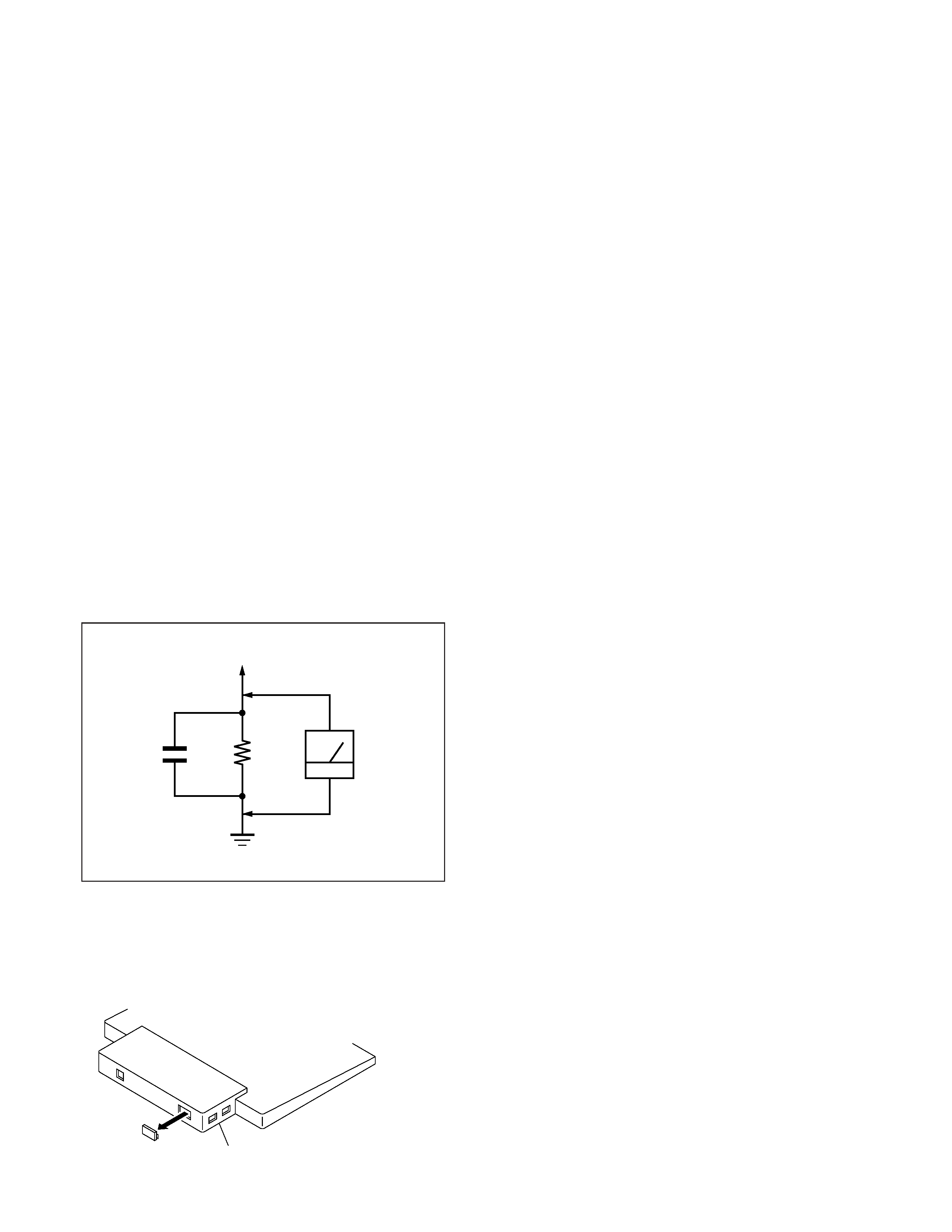
Fig. A. Using an AC voltmeter to check AC leakage.
SAFETY CHECK-OUT
1.5 k
0.15
µF
AC
Voltmeter
(0.75 V)
To Exposed Metal
Parts on Set
Earth Ground
CAUTION ON DAS (ECS) CONNECTOR
· The connector for DAS (ECS) adjustment is provided inside
the cover shown below. Be careful with an electrical shock
when connecting the connector with the power supplied. Also,
return the removed cover to the home position.
STAND
GDM-F400/F400T9
3
POWER SAVING FUNCTION
DIAGNOSIS
This monitor meets the power-saving guidelines set by VESA,
ENERGY STAR, and NUTEK. If the monitor is connected to a
computer or video graphics board that is DPMS (Display Power
Management Signaling) compliant, the monitor will
automatically reduce power consumption in three stages as shown
below.
* Figures reflect power consumption when no USB compatible
peripherals are connected to the monitor.
**When your computer enters the "active off" mode, the input signal is
cut and NO INPUT SIGNAL appears on the screen. After the time set
in "Changing the power saving delay time." (page 1-6) has elapsed, the
monitor enters the power saving mode.
To change the power saving delay time
See page 1-6.
Power mode
Power
consumption*
1 (power)
indicator
normal
operation
140 W (GDM-F400) green
1 standby
80 W (GDM-F400) green and orange
alternate
2 suspend
10 W (GDM-F400) green and orange
alternate
3 active off**
3 W (GDM-F400)
orange
power off
0 W
off
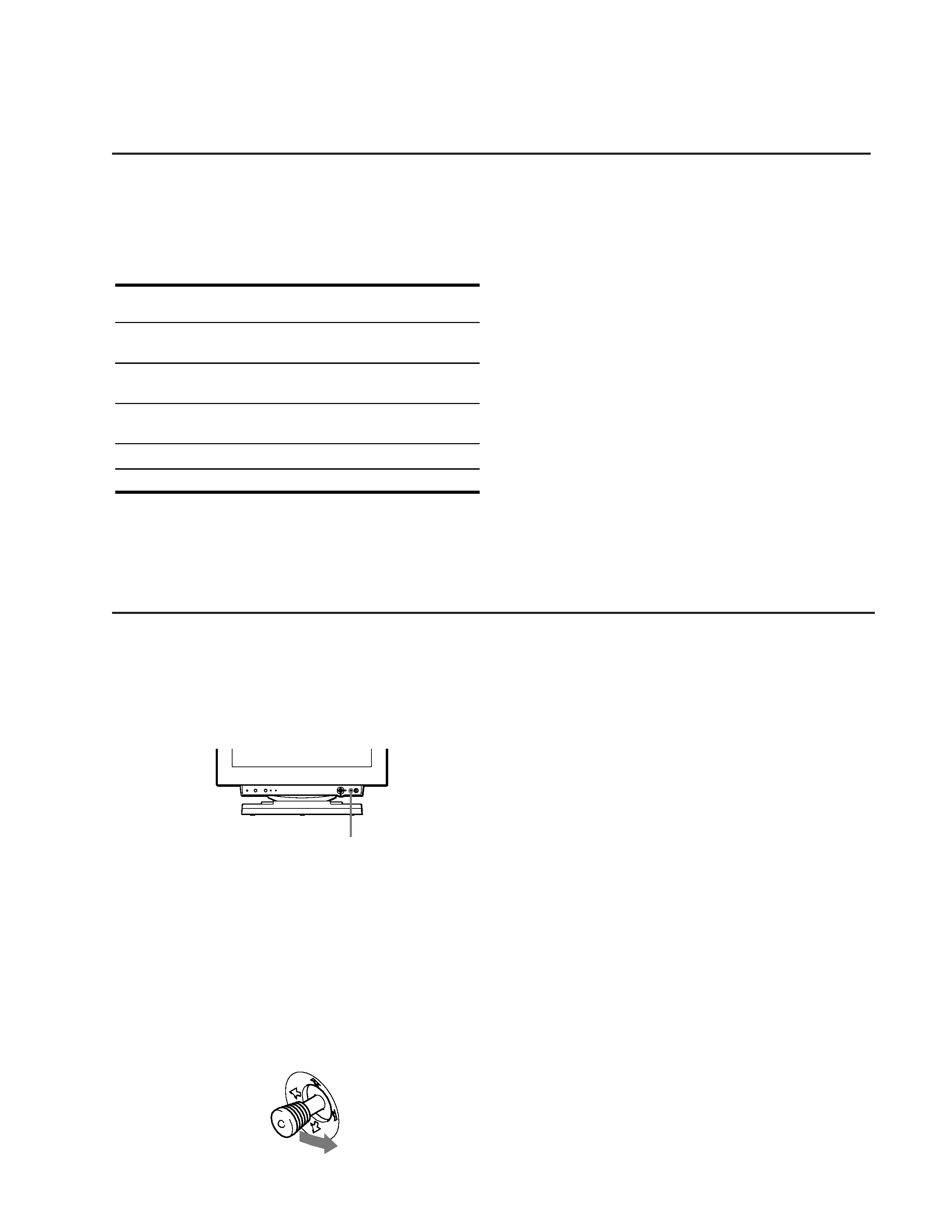
This monitor is equipped with a self-diagnosis function. If there is
a problem with your monitor or computer(s), the screen will go
blank and the 1 (power) indicator will either light up green or
flash orange. If the 1 (power) indicator is lit in orange, the
computer is in power saving mode. Try pressing any key on the
keyboard.
If the 1 (power) indicator is green
1 Remove any plugs from the video input 1 and 2
connectors, or turn off the connected computer(s).
2 Press the 1 (power) button to turn the monitor off
and on.
3 Move the joystick to the right for 2 seconds before
the monitor enters power saving mode.
If all four color bars appear (white, red, green, blue), the monitor
is working properly. Reconnect the video input cables and check
the condition of your computer(s).
If the color bars do not appear, there is a potential monitor failure.
Inform your authorized Sony dealer of the monitor's condition.
If the 1 (power) indicator is flashing orange
Press the 1 (power) button to turn the monitor off and
on.
If the 1 (power) indicator lights up green, the monitor is working
properly.
If the 1 (power) indicator is still flashing, there is a potential
monitor failure. Count the number of seconds between orange
flashes of the 1 (power) indicator and inform your authorized
Sony dealer of the monitor's condition. Be sure to note the model
name and serial number of your monitor. Also note the make and
model of your computer and video board.
RESET
ASC
INPUT
MENU
HD15
BNC
1 (power) indicator
GDM-F400/F400T9
4
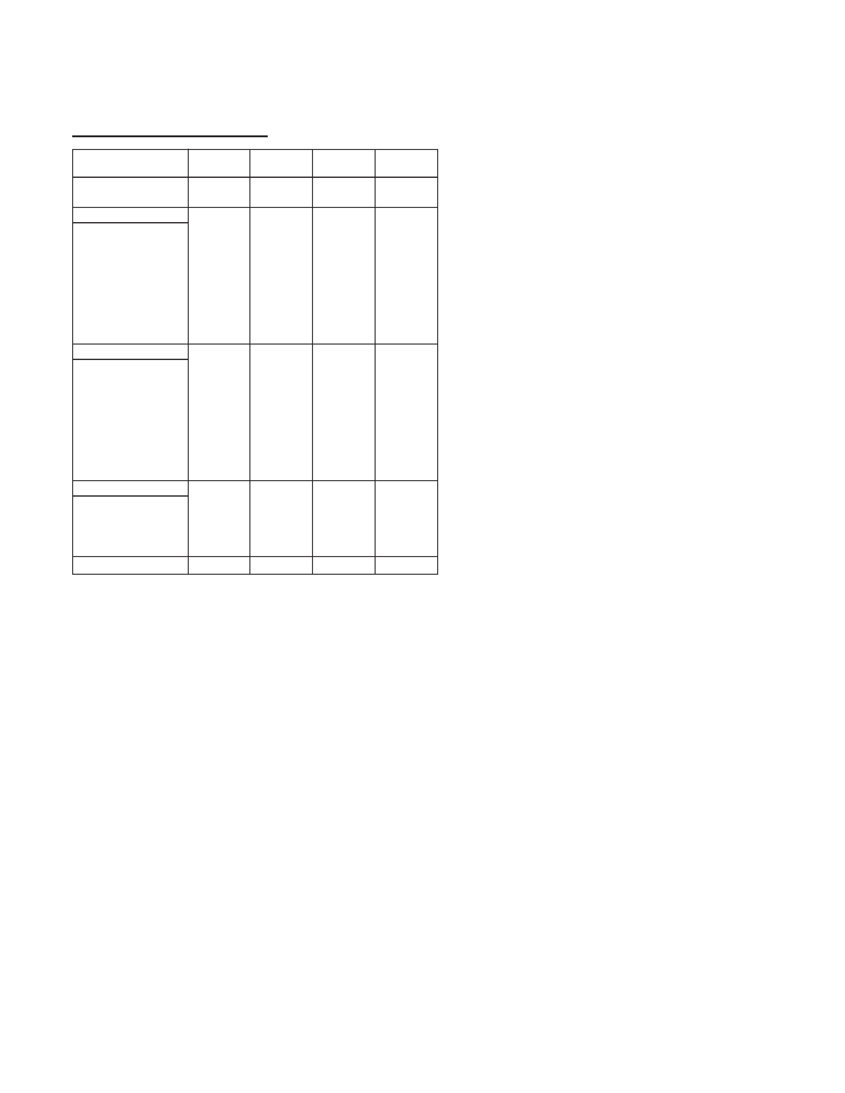
TIMING SPECIFICATION
MODE
TEST MODE
MODE AT PRODUCTION
MODE 1
MODE 2
MODE 3
MODE 4
RESOLUTION
738 X 414
1600 X 1200
1600 X 1200
1280 X 1024
CLOCK
28.322 MHz
229.5 MHz
202.5 MHz
157.5 MHz
HORIZONTAL
H-FREQ
31.469 kHz
106.25 kHz
93.75 kHz
91.146 kHz
usec
usec
usec
usec
H. TOTAL
31.777
9.412
10.667
10.971
H. BLK
5.72
2.44
2.765
2.844
H. FP
0.318
0.279
0.316
0.406
H. SYNC
3.813
0.837
0.948
1.016
H. BP
1.589
1.325
1.501
1.422
H. ACTIV
26.057
6.972
7.901
8.127
VERTICAL
V. FREQ(HZ)
70.087 Hz
85 Hz
75 Hz
85.024 Hz
lines
lines
lines
lines
V. TOTAL
449
1250
1250
1072
V. BLK
35
50
50
48
V. FP
5
1
1
1
V. SYNC
2
3
3
3
V. BP
28
46
46
44
V. ACTIV
414
1200
1200
1024
SYNC
INT(G)
NO
NO
NO
NO
EXT(H/V)/POLARITY
YES N/P
YES P/P
YES P/P
YES P/P
EXT(CS) /POLARITY
NO
NO
NO
NO
INT/NON INT
NON INT
NON INT
NON INT
NON INT
SIZE
352 X 264 mm 352 X 264 mm 352 X 264 mm 330 X 264 mm

GDM-F400/F400T9
5
TABLE OF CONTENTS
Section
Title
Page
1. GENERAL ................................................................. 1-1
2. DISASSEMBLY
2-1.
Cabinet Removal ............................................... 2-1
2-2.
A Board Removal .............................................. 2-1
2-3.
AC Inlet and Rear Shield Removal .................. 2-2
2-4.
D Board Removal .............................................. 2-2
2-5.
Service Position .................................................. 2-3
2-6.
US Board Removal ............................................. 2-3
2-7.
Bezel and H Board Removal .............................. 2-4
2-8.
Picture Tube Removal ....................................... 2-5
2-9.
Harness Location ................................................ 2-6
3. SAFETY RELATED ADJUSTMENT ............. 3-1
4. ADJUSTMENTS ..................................................... 4-1
5. DIAGRAMS
5-1.
Block Diagrams .................................................. 5-1
5-2.
Frame Shcematic Diagram ................................. 5-5
5-3.
Circuit Boards Location ..................................... 5-7
5-4.
Schematic Diagrams and Printed Wiring
Boards ................................................................. 5-8
(1)
Schematic Diagrams of US Board .................... 5-9
(2)
Schematic Diagrams of A Board ...................... 5-11
(3)
Schematic Diagram of H Board ........................ 5-14
(4)
Schematic Diagram of D Board ........................ 5-15
5-5.
Semiconductors ................................................. 5-29
6. EXPLODED VIEWS
6-1.
Chassis ............................................................... 6-1
6-2.
Picture Tube ...................................................... 6-2
6-3.
Packing Materials .............................................. 6-3
7. ELECTRICAL PARTS LIST ............................ 7-1