SERVICE MANUAL
US Model
Canadian Model
AEP Model
Mexican Model
UK Model
CD/DVD PLAYER
DVP-PQ2
RMT-D148A
System
Laser: Semiconductor laser
Signal format system:
*(US,CND,MX): NTSC
*(AEP,UK): PAL/NTSC
Outputs
(Jack name: Jack type/Output level/Load impedance)
AUDIO OUT L/R: Phonojack/2 Vrms/10 k
DIGITAL OUT (COAXIAL): Phonojack/0.5 Vp-p/75
VIDEO OUT:
Phonojack/1.0 Vp-p/75
S-VIDEO OUT: 4-pin mini DIN/
Y: 1.0 Vp-p
C: 0.3 Vp-p (PAL), 0.286 Vp-p (NTSC)/75
HEADPHONES/EARPHONES JACK:
Stereo mini-jack/9 m W + 9 m W/32
General
Power requirements:
*(US,CND,MX): 120 V, 60 Hz
*(AEP,UK): 220-240 V, 50/60 Hz
Power consumption: 9 W
Dimensions (approx.):
190
× 147 × 235 mm (7 × 5 7/8 × 9 in.)
(w/h/d)
Mass (approx.): 1.3 kg (2.9 lbs)
Operating temperature: 5°C to 35°C (41°F to 95°F)
Operating humidity: 25-80%
Supplied accessories
Operating Instructions (1)
Audio/video cord (1)
Remote (1)
AA (R6) size batteries (2)
EURO AV adaptor (AEP,UK)* (1)
Design sheet
Specifications and design are subject to change
without notice.
ENERGY STAR is a U.S. registered mark. As an
ENERGY STAR Partner, Sony Corporation has
determined that this product meets the ENERGY STAR
guidelines for energy efficiency.
* Refer Pg.4-1 for Abbreviation
SPECIFICATIONS
2
WARNING!!
WHEN SERVICING, DO NOT APPROACH THE LASER
EXIT WITH THE EYE TOO CLOSELY. IN CASE IT IS
NECESSARY TO CONFIRM LASER BEAM EMISSION,
BE SURE TO OBSERVE FROM A DISTANCE OF
MORE THAN 25 cm FROM THE SURFACE OF THE
OBJECTIVE LENS ON THE OPTICAL PICK-UP BLOCK.
CAUTION
Use of controls or adjustments or performance of procedures
other than those specified herein may result in hazardous ra-
diation exposure.
ATTENTION AU COMPOSANT AYANT RAPPORT
À LA SÉCURITÉ!
LES COMPOSANTS IDENTIFIÉS PAR UNE MARQUE
SUR LES DIAGRAMMES SCHÉMATIQUES ET LA LISTE
DES PIÈCES SONT CRITIQUES POUR LA SÉCURITÉ
DE FONCTIONNEMENT. NE REMPLACER CES COM-
POSANTS QUE PAR DES PIÈCES SONY DONT LES
NUMÉROS SONT DONNÉS DANS CE MANUEL OU
DANS LES SUPPLÉMENTS PUBLIÉS PAR SONY.
SAFETY-RELATED COMPONENT WARNING!!
COMPONENTS IDENTIFIED BY MARK
OR DOTTED
LINE WITH MARK
ON THE SCHEMATIC DIAGRAMS
AND IN THE PARTS LIST ARE CRITICAL TO SAFE
OPERATION. REPLACE THESE COMPONENTS WITH
SONY PARTS WHOSE PART NUMBERS APPEAR AS
SHOWN IN THIS MANUAL OR IN SUPPLEMENTS PUB-
LISHED BY SONY.
CAUTION:
The use of optical instrument with this product will increase eye
hazard.
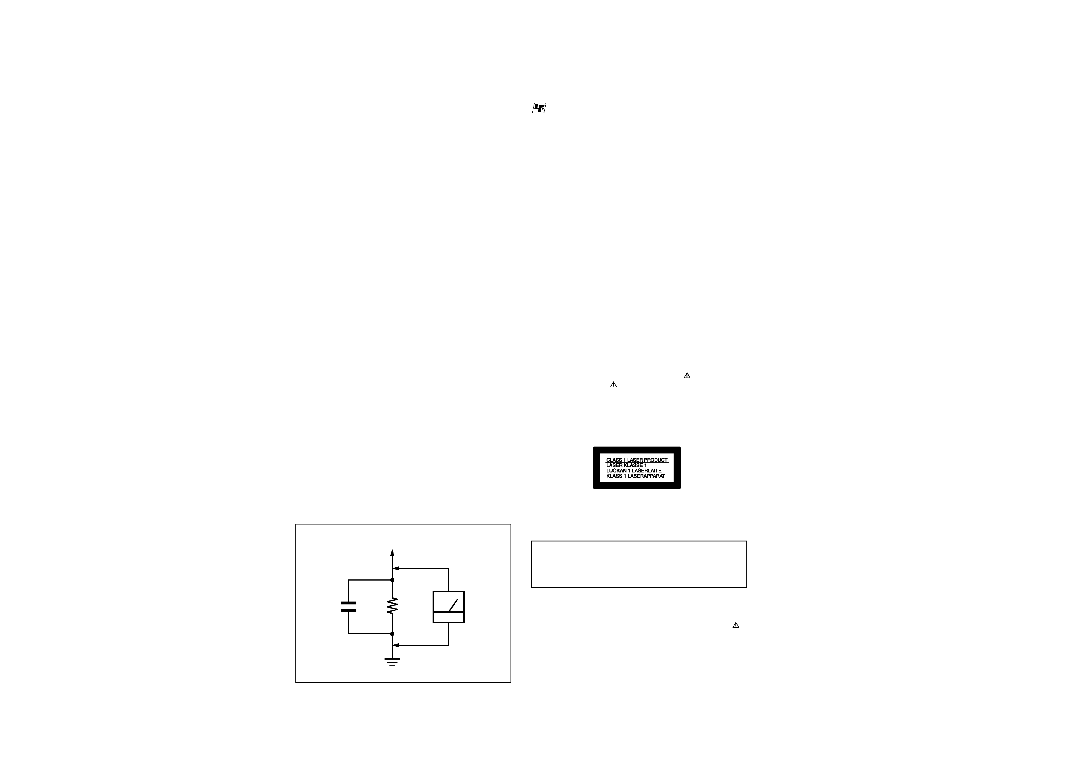
Fig. A.
Using an AC voltmeter to check AC leakage.
1.5 k
0.15 µF
AC
voltmeter
(0.75 V)
To Exposed Metal
Parts on Set
Earth Ground
LEAKAGE TEST
The AC leakage from any exposed metal part to earth ground
and from all exposed metal parts to any exposed metal part having
a return to chassis, must not exceed 0.5 mA (500 microamperes).
Leakage current can be measured by any one of three methods.
1. A commercial leakage tester, such as the Simpson 229 or RCA
WT-540A. Follow the manufacturers' instructions to use these
instruments.
2. A battery-operated AC milliammeter. The Data Precision 245
digital multimeter is suitable for this job.
3. Measuring the voltage drop across a resistor by means of a
VOM or battery-operated AC voltmeter. The "limit" indica-
tion is 0.75 V, so analog meters must have an accurate low-
voltage scale. The Simpson 250 and Sanwa SH-63Trd are ex-
amples of a passive VOM that is suitable. Nearly all battery
operated digital multimeters that have a 2 V AC range are suit-
able. (See Fig. A)
1. Check the area of your repair for unsoldered or poorly-sol-
dered connections. Check the entire board surface for solder
splashes and bridges.
2. Check the interboard wiring to ensure that no wires are
"pinched" or contact high-wattage resistors.
3. Look for unauthorized replacement parts, particularly transis-
tors, that were installed during a previous repair. Point them
out to the customer and recommend their replacement.
4. Look for parts which, though functioning, show obvious signs
of deterioration. Point them out to the customer and recom-
mend their replacement.
5. Check the line cord for cracks and abrasion. Recommend the
replacement of any such line cord to the customer.
6. Check the B+ voltage to see it is at the values specified.
7. Check the antenna terminals, metal trim, "metallized" knobs,
screws, and all other exposed metal parts for AC leakage.
Check leakage as described below.
SAFETY CHECK-OUT
After correcting the original service problem, perform the following
safety checks before releasing the set to the customer:
: LEAD FREE MARK
Unleaded solder has the following characteristics.
· Unleaded solder melts at a temperature about 40°C higher than
ordinary solder.
Ordinary soldering irons can be used but the iron tip has to be
applied to the solder joint for a slightly longer time.
Soldering irons using a temperature regulator should be set to
about 350°C .
Caution: The printed pattern (copper foil) may peel away if the
heated tip is applied for too long, so be careful!
· Strong viscosity
Unleaded solder is more viscous (sticky, less prone to flow) than
ordinary solder so use caution not to let solder bridges occur
such as on IC pins, etc.
· Usable with ordinary solder
It is best to use only unleaded solder but unleaded solder may
also be added to ordinary solder.

3
TABLE OF CONTENTS
SERVICE NOTE ................................................................... 4
1.
GENERAL ................................................................... 1
2.
DISASSEMBLY
2-1.
LID Assembly Removal ................................................. 2-1
2-2.
Disk Base Assembly Removal ...................................... 2-1
2-3.
Base Unit Removal ........................................................ 2-1
2-4.
BU Holder Removal ....................................................... 2-1
2-5.
SW-406 Board Removal ................................................ 2-2
2-6.
HP-137 & Jack Plate Removal ...................................... 2-2
2-7.
Lower Case Removal .................................................... 2-2
2-8.
Power Switching Regulator Block Removal ................. 2-2
2-9.
Shield Plate Removal .................................................... 2-3
2-10. AV-77 Board Removal ................................................... 2-3
2-11. IF-106 Board Removal .................................................. 2-3
2-12. MB-108 & SW-407 Boards Removal ............................ 2-3
2-13. Circuit Boards Location ................................................. 2-4
3.
BLOCK DIAGRAMS
3-1.
Overall Block Diagram ................................................... 3-1
3-2.
System Control Block Diagram ..................................... 3-3
3-3.
RF/Servo Block Diagram ............................................... 3-5
3-4.
Signal Processor Block Diagram .................................. 3-7
3-5.
Video/Audio Block Diagram .......................................... 3-9
3-6.
Interface Control Block Diagram ................................... 3-11
3-7.
Power 1 Block Diagram ................................................. 3-13
3-8.
Power 2 Block Diagram ................................................. 3-15
4.
PRINTED WIRING BOARDS AND SCHEMATIC
DIAGRAMS
4-1.
Printed Wiring Boards and Schematic Diagrams ........ 4-1
4-2.
Frame Schematic Diagram ............................................ 4-3
Waveforms ..................................................................... 4-5
·
MB-108 Printed Wiring Board .................................. 4-7
·
MB-108 (System Control) Schematic Diagram ....... 4-9
·
MB-108 (Motor Drive) Schematic Diagram ............. 4-11
·
MB-108 (Servo) Schematic Diagram ....................... 4-13
·
MB-108 (AV Decoder) Schematic Diagram ............ 4-15
·
MB-108 (Audio DAC, PLL) Schematic Diagram ...... 4-17
·
MB-108 Board Differential Part List ......................... 4-17
·
AV-77 Printed Wiring Board ..................................... 4-19
·
AV-77 (Audio/Video Out) Schematic Diagram ........ 4-21
·
AV-77 Board Differential Part List ............................ 4-23
·
IF-106 Printed Wiring Board .................................... 4-25
·
IF-106 (Interface Control) Schematic Diagram ....... 4-27
·
SW-406, SW-407 Printed Wiring Boards ................ 4-29
·
SW-406 (Function Switch), SW-407 (Door Switch)
Schematic Diagram ............................................. 4-31
·
HP-137 Printed Wiring Board .................................. 4-33
·
HP-137 (Headphone) Schematic Diagram ............. 4-35
·
DPSN-20CP Printed Wiring Board .......................... 4-37
·
DPSN-20CP (Switching Regulator)
Schematic Diagram ............................................. 4-39
·
DPSN-20CP-2 Printed Wiring Board ....................... 4-41
·
DPSN-20CP-2 (Switching Regulator)
Schematic Diagram ............................................. 4-43
5.
IC PIN FUNCTION DESCRIPTION
5-1.
System Control Pin Function
(MB-108 BOARD IC104: MB9130RPFV-G-BND-E1) ... 5-1
6.
TEST MODE
6-1.
General Description ...................................................... 6-1
6-2.
Starting Test Mode ......................................................... 6-1
6-3.
Syscon Diagnosis .......................................................... 6-1
6-4.
Drive Auto Adjustment ................................................... 6-5
6-5.
Drive Manual Operation ................................................ 6-7
6-6.
Emergency History ........................................................ 6-10
6-7.
Version Information ....................................................... 6-11
6-8.
Video Level Adjustment ................................................ 6-11
6-9.
Troubleshooting ............................................................. 6-11
7.
ELECTRICAL ADJUSTMENT
7-1.
Power Supply Check ..................................................... 7-1
7-2.
Adjustment of Video System ......................................... 7-2
1.
Video Level Adjustment ................................................ 7-2
2.
Checking S Video Output S-Y ....................................... 7-2
3.
Checking S Video Output S-C ...................................... 7-2
7-3.
Adjustment Related Parts Arrangement ....................... 7-3
8.
REPAIR PARTS LIST
8-1.
Exploded Views ............................................................. 8-1
8-1-1. Disk Base Section .................................................... 8-1
8-1-2. Lower Case Section ................................................. 8-2
8-2.
Electrical Parts List ........................................................ 8-3
4
SERVICE NOTE
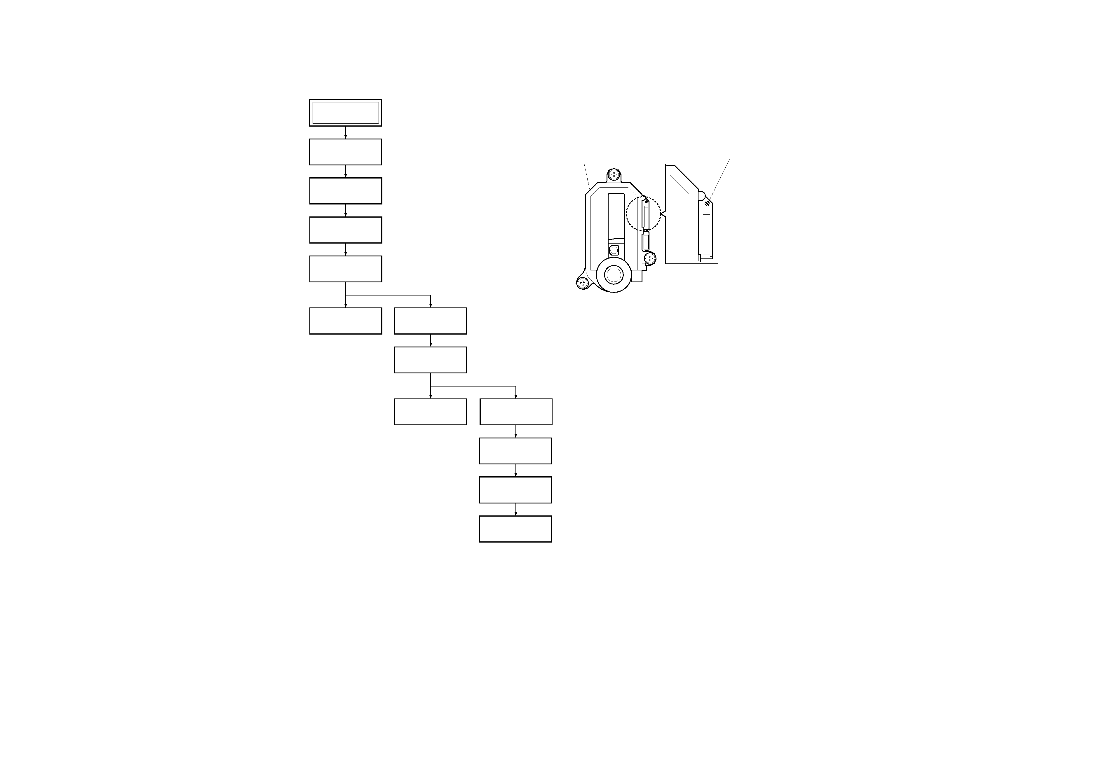
1.
DISASSEMBLY
· This set can be disassembled in the order shown below.
Set
Lid Assembly
(Page 2-1)
BU Holder
(Page 2-1)
SW-406 Board
(Page 2-2)
Disk Base Assembly
(Page 2-1)
Base Unit
(Page 2-1)
HP-137 Board &
Jack Plate
(Page 2-2)
Lower Case
(Page 2-2)
AV-77 Board
(Page 2-3)
IF-106 Board
(Page 2-3)
MB-108 &
SW-407 Boards
(Page 2-3)
Shield Plate
(Page 2-3)
Power Switching
Regulator Block
(Page 2-2)
2.
PRECAUTIONS FOR USE OF BASE UNIT
As the laser diode in the base unit is easily damaged by static
electricity, desolder the laser tap of the flexible board of the base
unit when using it.
Before disconnecting the connector, solder first. Before connect-
ing the connector, be careful not to remove the solder. Also take
adequate measures to prevent damage by static electricity. Handle
the flexible board with care as it breaks easily.
Base unit
Laser tap
1-1
SECTION
1
GENERAL
DVP-PQ2
This
section
is
extracted
from
instruction
manual
(3-082-452-12).
DVP-PQ2
Operating Instructions
© 2003 Sony Corporation Printed in Malaysia
3-082-452-12(1)
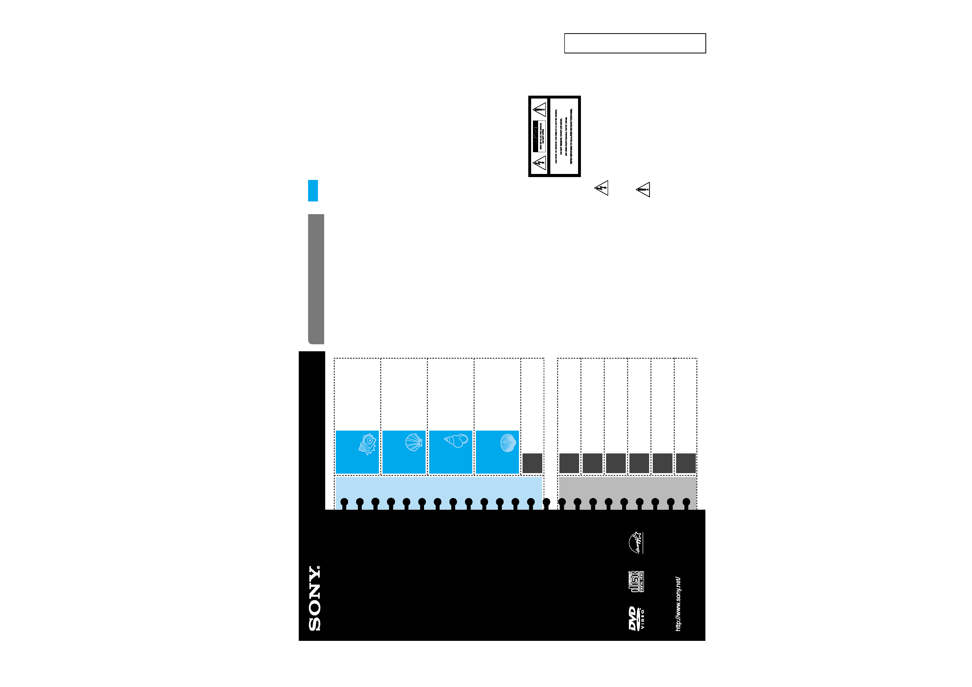
Connecting
the Player
Playing Discs
DVD/VIDEO CD/CD/MP3
Using the
Remote
SHUFFLE/REPEAT/AUDIO/
ANGLE/SUBTITLE/TVS
(surround)
Settings and
Adjustments
Playing MP3 audio tracks
from a list
Limiting Playback
Using the Design Sheet
Connecting Other
Components
Precautions
Troubleshooting
Note
This equipment has been tested and found to comply
with the limits for a Class B digital device, pursuant
to Part 15 of the FCC Rules. These limits are designed
to provide reasonable protection against harmful
interference in a residential installation. This
equipment generates, uses, and can radiate radio
frequency energy and if not installed and used in
accordance with the instructions, may cause harmful
interference to radio communications. However,
there is no guarantee that interference will not occur
in a particular installation. If this equipment does
cause harmful interference to radio or television
reception, which can be determined by turning the
equipment off and on, the user is encouraged to try
to correct the interference by one or more of the
following measures:
Reorient or relocate the receiving antenna.
Increase the separation between the equipment and
receiver.
Connect the equipment into an outlet on a circuit
different from that to which the receiver is
connected.
Consult the dealer or an experienced radio/TV
technician for help.
For customers in the U.S.A. and Canada
This symbol is intended to alert the user
to the presence of uninsulated
"dangerous voltage" within the
product's enclosure that may be of
sufficient magnitude to constitute a risk
of electric shock to persons.
This symbol is intended to alert the user
to the presence of important operating
and maintenance (servicing) instructions
in the literature accompanying the
appliance.
WARNING
To prevent fire or shock hazard, do not expose the
player to rain or moisture.
To avoid electrical shock, do not open the cabinet.
Refer servicing to qualified personnel only.
Power cord (mains lead) must only be changed at a
qualified service shop.
CAUTIONS
· The use of optical instruments with this product
will increase eye hazard. As the laser beam used in
this CD/DVD player is harmful to eyes, do not
attempt to disassemble the cabinet.
Refer servicing to qualified personnel only.
· TO PREVENT ELECTRIC SHOCK, MATCH WIDE
BLADE OF PLUG TO WIDE SLOT AND FULLY
INSERT.
PRECAUTIONS
· The nameplate is located at the bottom of the
player.
· To prevent fire or shock hazard, do not place
objects filled with liquids, such as vases, on the
apparatus.
For customers in the U.S.A.
Owner's Record
The model and serial numbers are located at the
bottom of the player. Record the serial number in the
space provided below. Refer to them whenever you
call upon your Sony dealer regarding this product.
Model No. DVP-PQ2
Serial No. ___________________
You are cautioned that any change or modifications
not expressly approved in this manual could void
your authority to operate this equipment.
Blue
Side
c
c
c
Brown
Side
c
c
c
CD/DVD Player
Playable discs and special
words