Chinese Model
Hong Kong Model
Spanish Model
E Model
SERVICE MANUAL
CD/DVD PLAYER
MICROFILM
SPECIFICATIONS
· Refer to the OPERATION MANUAL (9-921-669-21) and
DVD MECHANISM OPERATION MANUAL (9-921-669-31)
for DVD mechanism.
DVP-M35
RMT-D102E
-- 2 --
SAFETY-RELATED COMPONENT WARNING!!
COMPONENTS IDENTIFIED BY MARK
! OR DOTTED LINE WITH
MARK
! ON THE SCHEMATIC DIAGRAMS AND IN THE PARTS
LIST ARE CRITICAL TO SAFE OPERATION. REPLACE THESE
COMPONENTS WITH SONY PARTS WHOSE PART NUMBERS
APPEAR AS SHOWN IN THIS MANUAL OR IN SUPPLEMENTS
PUBLISHED BY SONY.
1.
Check the area of your repair for unsoldered or poorly-soldered
connections. Check the entire board surface for solder splashes
and bridges.
2.
Check the interboard wiring to ensure that no wires are
"pinched" or contact high-wattage resistors.
3.
Look for unauthorized replacement parts, particularly
transistors, that were installed during a previous repair. Point
them out to the customer and recommend their replacement.
4.
Look for parts which, through functioning, show obvious signs
of deterioration. Point them out to the customer and
recommend their replace-ment.
5.
Check the B+ voltage to see it is at the values specified.
6.
Flexible Circuit Board Repairing
· Keep the temperature of the soldering iron around 270°C
during repairing.
· Do not touch the soldering iron on the same conductor of the
circuit board (within 3 times).
· Be careful not to apply force on the conductor when soldering
or unsoldering.
SAFETY CHECK-OUT
After correcting the original service problem, perform the following
safety checks before releasing the set to the customer.
WARNING!!
WHEN SERVICING, DO NOT APPROACH THE LASER
EXIT WITH THE EYE TOO CLOSELY. IN CASE IT IS
NECESSARY TO CONFIRM LASER BEAM EMISSION,
BE SURE TO OBSERVE FROM A DISTANCE OF MORE
THAN 25 cm FROM THE SURFACE OF THE OBJECTIVE
LENS ON THE OPTICAL PICK-UP BLOCK.
CAUTION:
The use of optical instrument with this product will increase eye
hazard.
CAUTION
Use of controls or adjustments or performance procedures other
than those specified herein may result in hazardous radiation
exposure.
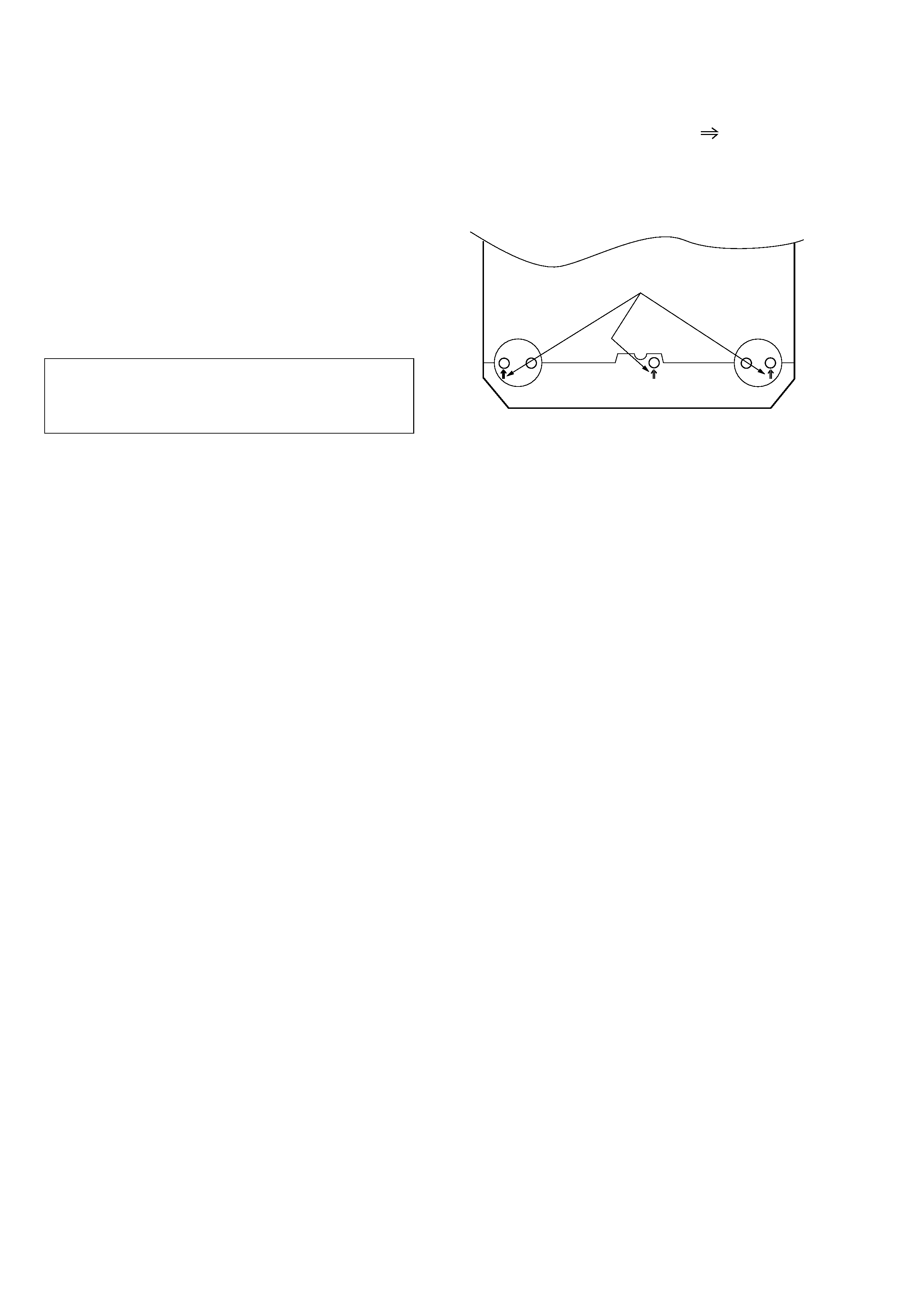
NOTE
There is no screw at three screwing marked "
" positions on the
bottom originally at the factory.
But there is no problem when screwing in using the screws 3 mm
(dia.)
× 10 mm (length).
-- Bottom View --
(Front Side)
Screwing marks

-- 3 --
TABLE OF CONTENTS
SERVICE NOTE
1.
DISK REMOVAL PROCEDURE (at POWER OFF) .................... 4
2.
NOTE ON MOUNTING SLED MOTOR ................................. 4
3.
REPLACING OPTICAL PICK-UP ............................................... 5
3-1.
Handling .......................................................................................... 5
4.
NOTE ON ASSEMBLING MECHANICAL DECK .................. 6
4-1.
Application of Grease ..................................................................... 6
4-2.
Cleaning Spindle Motor Turntable ................................................. 7
4-3.
Aligning Phase of Cam Gear and Drive Gear ................................ 7
4-4.
Deformation of Insulator ................................................................ 7
4-5.
Note on connecting OPT Harness .................................................. 7
4-6.
Note on Mounting FG-43 Board .................................................... 8
4-7.
Note on Mounting TK-47 Board .................................................... 8
1.
GENERAL
Getting Started
Unpacking ........................................................................................................... 1-1
Hooking Up the System ...................................................................................... 1-1
Necessary Setup Before Using the Player .......................................................... 1-1
Selecting the Language for On-screen Display .................................................. 1-1
Basic Operations
Playing a DVD .................................................................................................... 1-2
Playing a CD/VIDEO CD .................................................................................. 1-3
Playing Discs in Various Modes
Using the On-Screen Display ............................................................................. 1-4
Using the Front Panel Display ............................................................................ 1-4
Playing Repeatedly (Repeat Play) ...................................................................... 1-5
Playing in Random Order (Shuffle Play) ........................................................... 1-5
Creating Your Own Program (Program Play) ..................................................... 1-5
Resuming Playback from the Point Where
You Stopped a Disc (Resume Play) .................................................................... 1-6
Reducing the Picture Noise
(DNR: Digital Video Noise Reduction) .............................................................. 1-6
Changing the Sounds .......................................................................................... 1-6
Displaying the Subtitles ...................................................................................... 1-6
Changing the Angles ........................................................................................... 1-6
Limiting Playback by Children (Parental Control) ............................................ 1-6
Controlling the TV or the amplifier with
the Supplied Remote ........................................................................................... 1-7
Settings and Adjustments
Using the Setup Display ..................................................................................... 1-8
Setting the Language for Displaying and Sound (LANGUAGE SETUP) ......... 1-8
Settings for Display (INITIAL SETUP 1) .......................................................... 1-8
Settings for Sound (INITIAL SETUP 2) ............................................................ 1-8
Additional Information
Precautions ......................................................................................................... 1-9
Notes on Discs .................................................................................................... 1-9
Troubleshooting .................................................................................................. 1-9
Self-diagnosis Function ...................................................................................... 1-9
Index to Parts and Controls .............................................................................. 1-10
Setup Display Item List .................................................................................... 1-10
Language Code List .......................................................................................... 1-11
2.
DISASSEMBLY
2-1.
UPPER CASE ............................................................................. 2-1
2-2.
FRONT PANEL BLOCK ASSEMBLY ...................................... 2-1
2-3.
AU-199 BOARD ......................................................................... 2-2
2-4.
MB-78 BOARD .......................................................................... 2-2
2-5.
TK-47 BOARD, MECHANISM DECK ..................................... 2-3
2-6.
TRAY .......................................................................................... 2-3
2-7.
OPTICAL DEVICE .................................................................... 2-4
2-8.
INTERNAL VIEWS ................................................................... 2-4
2-9.
CIRCUIT BOARDS LOCATION ............................................... 2-5
3.
BLOCK DIAGRAMS
3-1.
OVERALL BLOCK DIAGRAM ................................................ 3-1
3-2.
RF/SERVO BLOCK DIAGRAM ................................................ 3-3
3-3.
VIDEO/AUDIO BLOCK DIAGRAM ........................................ 3-5
3-4.
SYSTEM CONTROL BLOCK DIAGRAM ............................... 3-7
3-5.
MODE CONTROL BLOCK DIAGRAM ................................... 3-9
3-6.
POWER SUPPLY BLOCK DIAGRAM ................................... 3-11
4.
PRINTED WIRING BOARDS AND
SCHEMATIC DIAGRAMS
4-1.
FRAME SCHEMATIC DIAGRAM ........................................... 4-1
4-2.
PRINTED WIRING BOARDS AND
SCHEMATIC DIAGRAMS ........................................................ 4-3
· TK-47 (RF, SERVO) PRINTED WIRING BOARD ................ 4-4
· TK-47 (RF, SERVO) SCHEMATIC DIAGRAM ..................... 4-7
· MB-78 (VIDEO, SERVO/SYSTEM CONTROL, AUDIO)
PRINTED WIRING BOARD ...................................... 4-12
· MB-78 (DSP) SCHEMATIC DIAGRAM .............................. 4-17
· MB-78 (AV DECODER) SCHEMATIC DIAGRAM ............ 4-20
· MB-78 (VIDEO ENCODER) SCHEMATIC DIAGRAM ..... 4-23
· MB-78 (INTERFACE) SCHEMATIC DIAGRAM ................ 4-26
· MB-78 (MOTOR DRIVE) SCHEMATIC DIAGRAM .......... 4-29
· MB-78 (POWER SUPPLY) SCHEMATIC DIAGRAM ........ 4-31
· MB-78 (DIGITAL PROCESS 1)
SCHEMATIC DIAGRAM ........................................... 4-33
· MB-78 (DIGITAL PROCESS 2)
SCHEMATIC DIAGRAM ........................................... 4-37
· FG-43 (SLED MOTOR), HP-98 (PHONES)
PRINTED WIRING BOARDS AND
SCHEMATIC DIAGRAMS ......................................... 4-41
· AU-199 (VIDEO/AUDIO INPUT/OUTPUT)
SCHEMATIC DIAGRAM ........................................... 4-44
· AU-199 (VIDEO/AUDIO INPUT/OUTPUT)
PRINTED WIRING BOARD ...................................... 4-47
· FL-90 (DISPLAY, OPERATION SWITCHES),
LE-21 (LED) PRINTED WIRING BOARDS ........................ 4-49
· FL-90 (DISPLAY, OPERATION SWITCHES),
LE-21 (LED) SCHEMATIC DIAGRAM ............................... 4-51
· POWER BLOCK HS-930SH (SWITCHING REGULATOR)
PRINTED WIRING BOARD ...................................... 4-53
· POWER BLOCK HS-930SH (SWITCHING REGULATOR)
SCHEMATIC DIAGRAM ........................................... 4-55
· POWER BLOCK HS-930SF (SWITCHING REGULATOR)
PRINTED WIRING BOARD ...................................... 4-57
· POWER BLOCK HS-930SF (SWITCHING REGULATOR)
SCHEMATIC DIAGRAM ........................................... 4-59
5.
TEST MODE
5-1.
How to Enter Test Mode ............................................................. 5-1
5-2.
System Control Diagnosis ........................................................... 5-1
5-2-1. Selection of Check Items ............................................................ 5-2
5-2-1-1. Testing the Selected Item .......................................................... 5-2
5-2-1-2. Testing All Items ....................................................................... 5-3
5-2-2. Error Display ............................................................................... 5-3
5-2-3. Diagnosis Check Item List .......................................................... 5-4
5-2-4. Brief Description of Check Procedures ...................................... 5-5
5-2-5. Diagnosis Error Code Table ...................................................... 5-17
5-3.
Drive Auto Adjustment ............................................................. 5-18
5-3-1. [0] ALL ..................................................................................... 5-18
5-3-2. [1] DVD Single Layer Disc ....................................................... 5-19
5-3-3. [2] CD disc ................................................................................ 5-20
5-3-4. [3] DVD dual layer disc ............................................................ 5-20
5-4.
Drive Manual Operation ............................................................ 5-21
5-4-1. Setup Displays In Accordance With
Selected Disc Type .................................................................... 5-21
5-4-2. Manual Control (1) .................................................................... 5-22
5-4-3. Manual Control (2) .................................................................... 5-22
5-4-4. Manual Control (3) .................................................................... 5-23
5-4-5. Manual Adjustment (1) ............................................................. 5-24
5-4-6. Manual Adjustment (2) ............................................................. 5-25
5-4-7. Automatic Adjustment .............................................................. 5-25
5-4-8. Check ........................................................................................ 5-26
5-5.
Mechanism Aging .................................................................... 5-27
5-6.
History of Emergencies ............................................................. 5-27
5-6-1. Hour Meter Display .................................................................. 5-27
5-6-2. History of Emergencies Display ............................................... 5-28
5-6-3. Initialization of Emergency History .......................................... 5-28
5-7.
Other Checks ............................................................................. 5-28
5-8.
Appendix ................................................................................... 5-29
5-8-1. Emergency Code Table ............................................................. 5-29
5-8-2. Drive Mechanism Mode Table .................................................. 5-30
5-8-3. Disc Status Table ....................................................................... 5-30
5-8-4. System Control Microprocessor Operation Mode Table ........... 5-30
6.
ELECTRICAL ADJUSTMENT
6-1.
POWER SUPPLY CHECK (MB-78 board) ............................... 6-1
6-2.
SYSTEM CONTROL ADJUSTMENT ...................................... 6-2
1.
27MHz Free Run (MB-78 board) ............................................... 6-2
6-3.
VIDEO SYSTEM ADJUSTMENT ............................................ 6-2
1.
Video Level Adjustment (AU-199, MB-78 boards) .................... 6-2
2.
S-terminal Output Check (AU-199 board) .................................. 6-2
3.
Checking Composite Video Output Y (AU-199 board) .............. 6-3
4.
Checking S Video Output S-C (AU-199 board) .......................... 6-3
5.
Checking S Video Output DC Level (AU-199 board) ................. 6-3
6-4.
ADJUSTMENT RELATED PARTS ARRANGEMENT ........... 6-4
7.
REPAIR PARTS LIST
7-1.
EXPLODED VIEWS
7-1-1. UPPER CASE, FRONT PANEL BLOCK ASSEMBLY ............ 7-1
7-1-2. CHASSIS BLOCK ASSEMBLY ................................................ 7-2
7-1-3. DVD MECHANISM CHASSIS BLOCK ASSEMBLY (1) ....... 7-3
7-1-3. DVD MECHANISM CHASSIS BLOCK ASSEMBLY (2) ....... 7-4
7-2.
ELECTRICAL PARTS LIST ...................................................... 7-5
-- 4 --
SERVICE NOTE
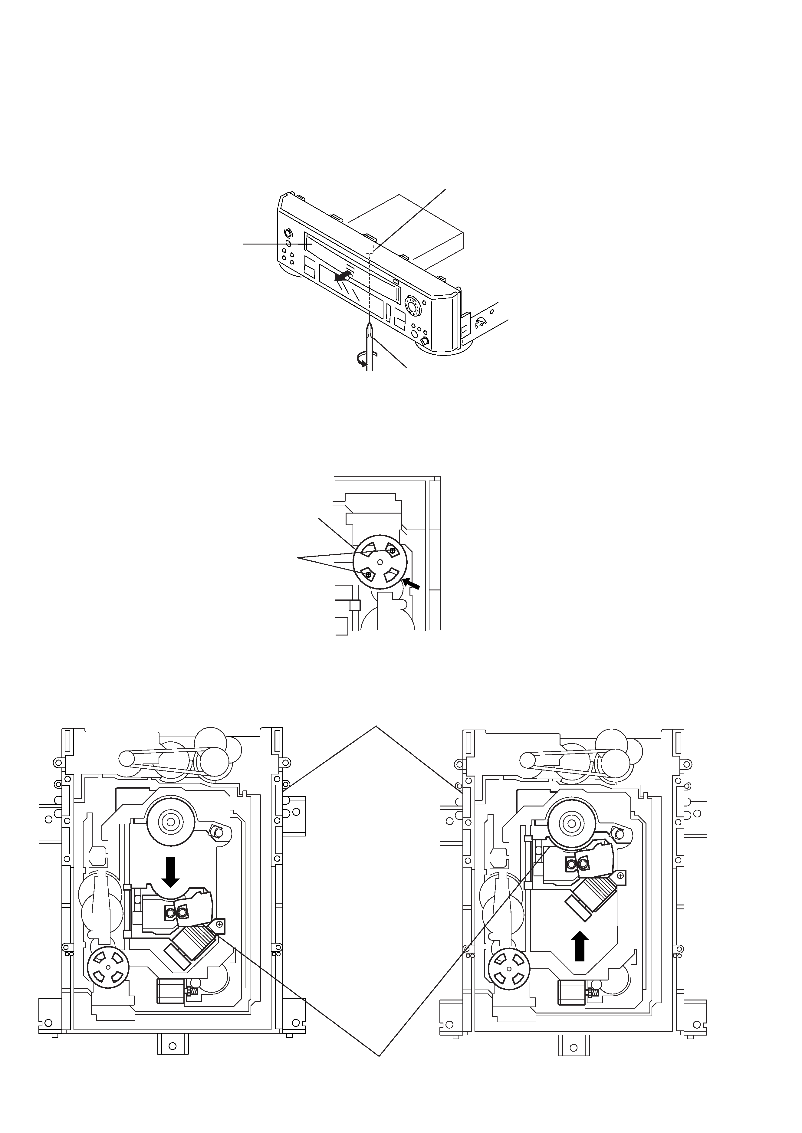
1.
DISK REMOVAL PROCEDURE (at POWER OFF)
1)
Insert a cross-tip screwdriver into a hole at the bottom, and rotate the cam gear 1 in direction A. (See Fig. 1)
Note: To prevent a damage of cam gear, rotate it in direction A by 1/4 turn.
2)
Draw out the tray 2 in direction B by hand, and remove a disk. (See Fig. 1)
Fig. 1
2.
NOTE ON MOUNTING SLED MOTOR
1)
Push the sled motor assy 1 toward direction A. (See Fig. 2)
2)
Tighten two screws 2 (M1.7
× 2.5).
Fig. 2
3)
Raising the MD block assy 3 90 º with the side down. confirm that the optical pick-up 4 falls by self weight. (See Fig. 3)
4)
Further, with the front side of MD block assy 3 up, confirm that the optical pick-up falls by self weight.
DVP-M35
1 Cam gear
2 Tray
B
A
` Screw Driver
Fig. 3
1 Sled motor assy
2 Two screws (M1.7
× 2.5)
3 MD block assy
4 Optical pick-up
Lower
Upper
Front side
Lower
Upper
Front side
-- 5 --
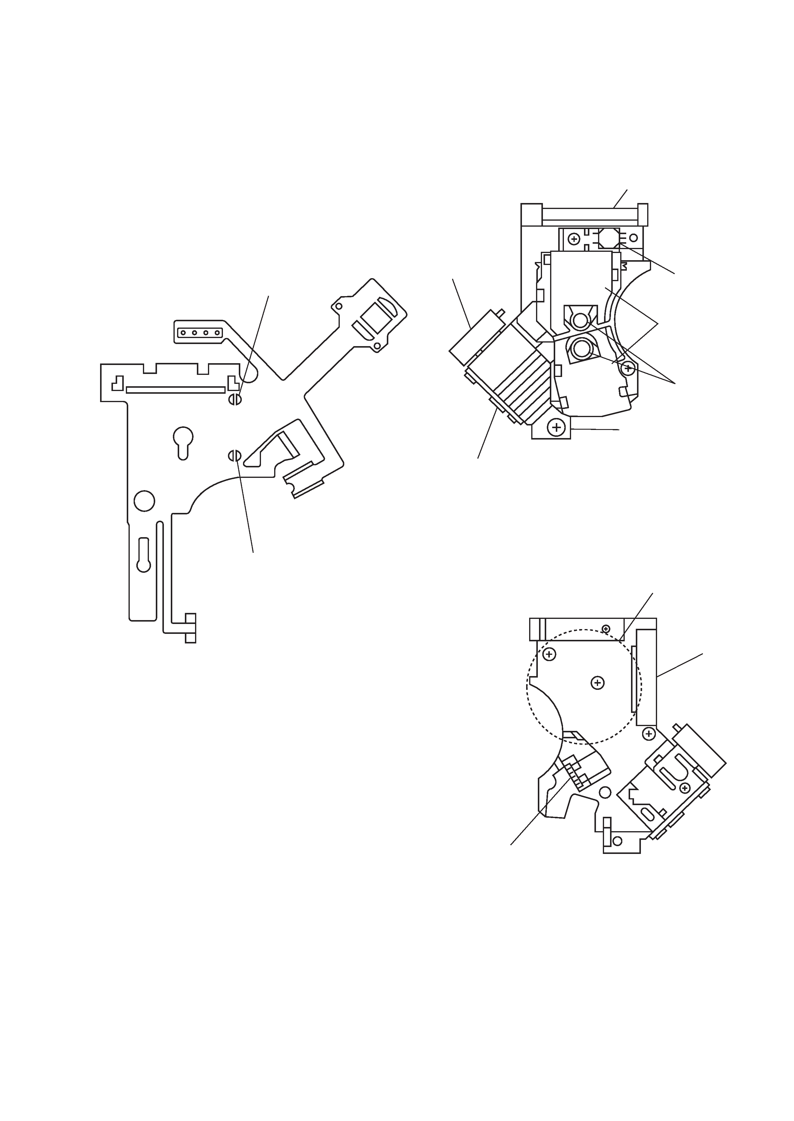
3.
REPLACING OPTICAL PICK-UP
3-1.
Handling
1)
A red laser diode for DVD requires more attention to static
electricity than general infrared laser diodes for CD.
Because its durability to static electricity is far weaker than
that of infrared laser diodes, always use an earth band when
handling the optical pick-up block as service parts.
2)
As for the flexible board KHS-180A (RP) packed as service
parts, the short lands have been soldered to protect from static
electricity. Accordingly, remove solders when replacing optical
pick-up. (See Fig. 4)
Fig. 4 Flexible board
3)
In handling the KHS-180A (RP), do not touch inhibited parts
shown in Fig. 5, but grip the slide base bearing and U-shaped
guide.
Touch inhibited parts
· Objective lens
· Skew sensor
· Laser holder
· Laser coupler
· Flexible board
· OEIC
· Lens actuator covers
Fig. 5 KHS-180A (RP)
DVD short land
CD short land
Slide base bearing
Skew sensor
Lens actuator
covers
Objective lenses
U-shaped guide
OEIC
Laser holder
Flexible board
Connector
Laser coupler