DVP-F5/FX1
RMT-D114A
US Model
Canadian Model
AEP Model
UK Model
Chinese Model
DVP-FX1/F5
Hong Kong Model
DVP-FX1
Australian Model
DVP-F5
SERVICE MANUAL
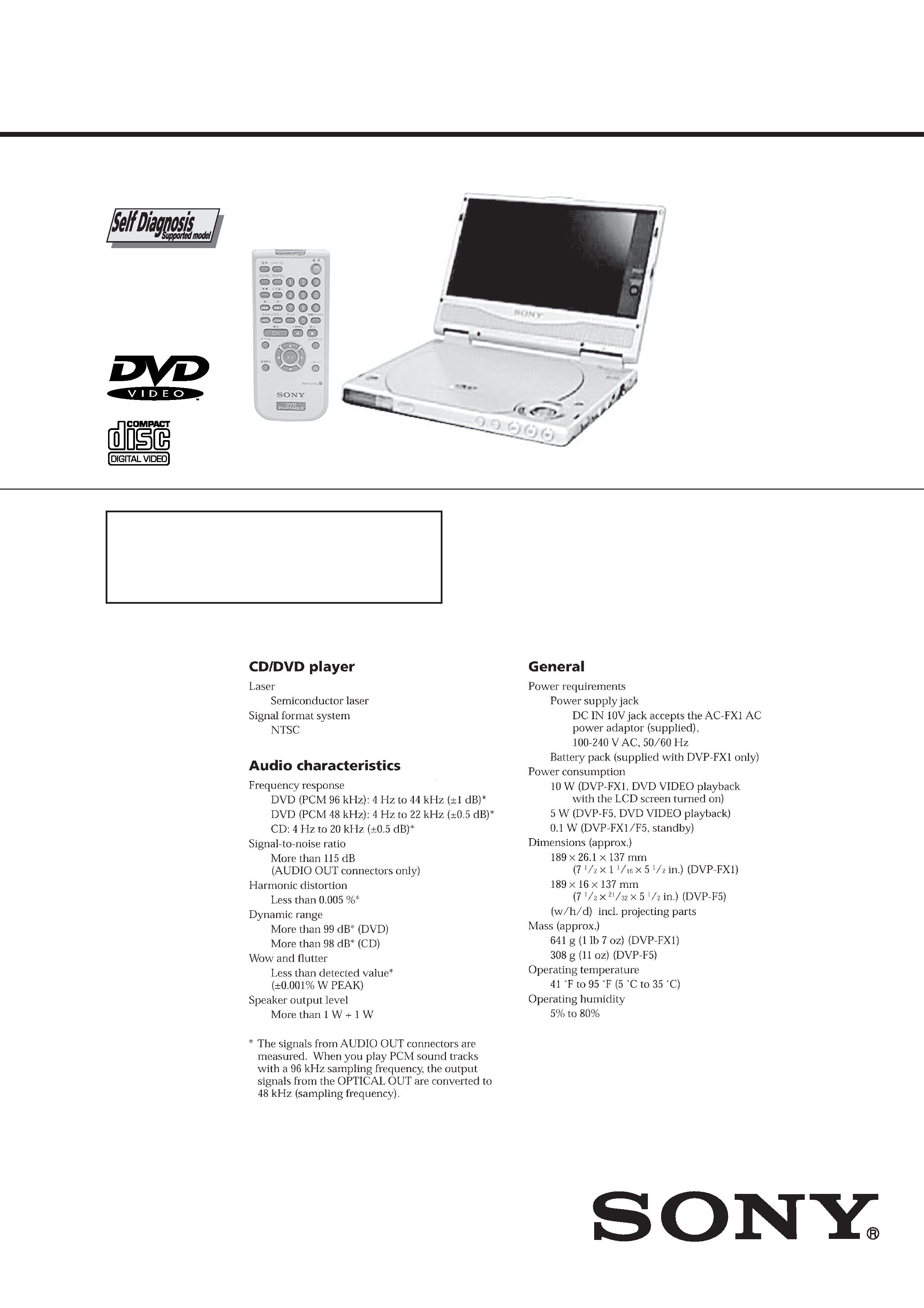
PORTABLE CD/DVD PLAYER
Photo: DVP-FX1
Manufactured under license from Dolby Laboratories
Licensing Corporation.
"DOLBY" and the double-D symbol ; are
trademarks of Dolby Laboratories Licensing
Corporation.
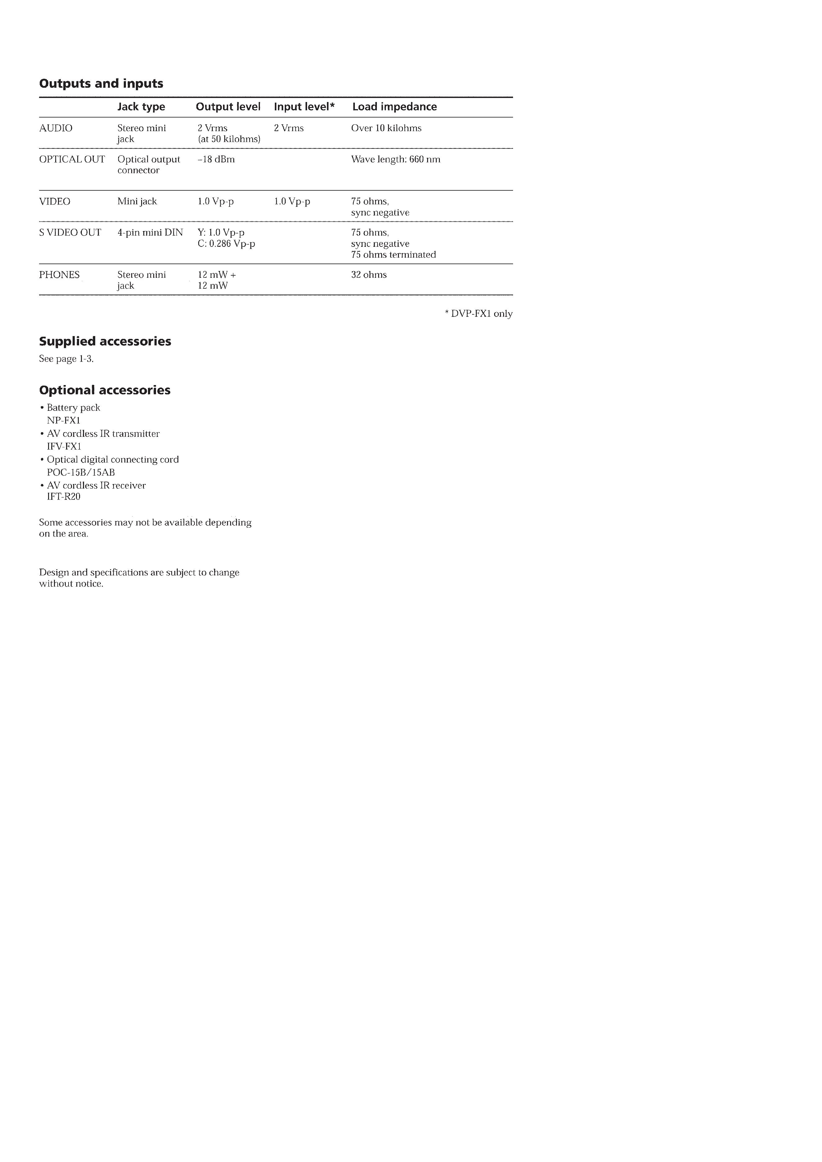
SPECIFICATIONS
-- 2 --
-- 3 --
SAFETY-RELATED COMPONENT WARNING!!
COMPONENTS IDENTIFIED BY MARK 0 OR DOTTED LINE WITH
MARK 0 ON THE SCHEMATIC DIAGRAMS AND IN THE PARTS
LIST ARE CRITICAL TO SAFE OPERATION. REPLACE THESE
COMPONENTS WITH SONY PARTS WHOSE PART NUMBERS
APPEAR AS SHOWN IN THIS MANUAL OR IN SUPPLEMENTS
PUBLISHED BY SONY.
1.
Check the area of your repair for unsoldered or poorly-soldered
connections. Check the entire board surface for solder splashes
and bridges.
2.
Check the interboard wiring to ensure that no wires are
"pinched" or contact high-wattage resistors.
3.
Look for unauthorized replacement parts, particularly
transistors, that were installed during a previous repair. Point
them out to the customer and recommend their replacement.
4.
Look for parts which, through functioning, show obvious signs
of deterioration. Point them out to the customer and
recommend their replacement.
5.
Check the B+ voltage to see it is at the values specified.
6.
Flexible Circuit Board Repairing
· Keep the temperature of the soldering iron around 270°C
during repairing.
· Do not touch the soldering iron on the same conductor of the
circuit board (within 3 times).
· Be careful not to apply force on the conductor when soldering
or unsoldering.
SAFETY CHECK-OUT
After correcting the original service problem, perform the following
safety checks before releasing the set to the customer.
ATTENTION AU COMPOSANT AYANT RAPPORT
À LA SÉCURITÉ!
LES COMPOSANTS IDENTIFÉS PAR UNE MARQUE 0 SUR LES
DIAGRAMMES SCHÉMATIQUES ET LA LISTE DES PIÈCES
SONT CRITIQUES POUR LA SÉCURITÉ DE FONCTIONNEMENT.
NE REMPLACER CES COMPOSANTS QUE PAR DES PIÈSES
SONY DONT LES NUMÉROS SONT DONNÉS DANS CE MANUEL
OU DANS LES SUPPÉMENTS PUBLIÉS PAR SONY.

-- 4 --
TABLE OF CONTENTS
1.
GENERAL
About this manual ··························································· 1-1
This Player Can Play the Following Discs ······················ 1-1
Precautions ······································································ 1-2
Notes about the Discs ······················································ 1-2
Getting Started
Unpacking ······································································· 1-3
Using the LCD Screen (DVP-FX1 only) ························· 1-3
TV Hookups ···································································· 1-3
Receiver (Amplifier) Hookups ········································ 1-4
5.1 Channel Surround Hookups ······································ 1-5
Connecting the AC Power Adapoter ································ 1-6
Using the Rechargeable Battery Pack ····························· 1-6
Selecting the Language for the On-Screen Display ········ 1-6
Plaing discs
Playing discs ···································································· 1-7
Searching for a Particular Point on a Disc ······················ 1-8
Resuming Playback from the Point Where You
Stopped the Disc (Resume Play) ································ 1-8
Using the DVD's Menu ··················································· 1-9
Playing VIDEO CDs with PBC Functions
(PBC Playback) ·························································· 1-9
Using the Display Window ············································ 1-10
Using Varioius Functions with the Control Menu
Using the Control Menu Display ··································· 1-11
Control Menu Item List ················································· 1-11
Searching for a Title/Chapter/Track/Index/Scene ········· 1-12
Cheking the Playing Time and Remaining Time ··········· 1-12
Selecting a Starting Point Using the Time Code ··········· 1-12
Viewing the Disc Information ······································· 1-13
Cheking the Sound ························································ 1-13
Displaying the Subtitles ················································· 1-14
Changing the Angles ····················································· 1-14
Digital Cinema Sound Settings ····································· 1-14
Checking the Play Information ······································ 1-15
Locking Discs (Custom Parental Control) ···················· 1-16
Creating Your Own Program (Program Play) ················ 1-16
Plaing in Random Order (Shuffle Play) ························ 1-17
Plaing Repeatedly (Repeat Play) ··································· 1-18
Repeating a Specific Portion (A-B Repeat) ·················· 1-18
Settings and Adjustments
Using the Setup Display ················································ 1-18
Setup Display Item List ················································· 1-19
Setting the Display Language or Sound Track
(LANGUAGE SETUP) ············································ 1-19
Settings for the Display (SCREEN SETUP) ················· 1-20
Custom Settings (CUSTOM SETUP) ··························· 1-21
Settings for the Sound (AUDIO SETUP) ······················ 1-22
Preventing the Buttons from being Pressed
Accidentally ······························································ 1-23
Additional Operations
Listening with Headphones ··········································· 1-23
Watching the Picture without Connecting Cables
LASER LINK ························································· 1-23
Watching the Picture of Other Equipment on the
LCD Screen (DVP-FX1 only) ·································· 1-24
Additional Information
Troubleshooting ····························································· 1-24
Self-diagnosis Function ················································· 1-26
Language Code List ······················································· 1-26
Index to Parts and Controls ··········································· 1-26
2.
DISASSEMBLY
2-1.
Cabinet Assy-1 ································································ 2-1
2-2.
Cabinet Assy-2 ································································ 2-1
2-3.
Cabinet Assy-3 ································································ 2-1
2-4.
CD, LID ··········································································· 2-2
2-5.
MB-90 Board, LC-68 Board, MD Comple ····················· 2-2
2-6.
Display Panel (FX1) ························································ 2-3
3.
BLOCK DIAGRAMS
3-1.
OVERALL BLOCK DIAGRAM (1/2) ··························· 3-1
3-2.
OVERALL BLOCK DIAGRAM (2/2) ··························· 3-3
3-3.
VIDEO OUT BLOCK DIAGRAM ································· 3-5
3-4.
RF BLOCK DIAGRAM (1/2) ········································· 3-7
3-5.
RF BLOCK DIAGRAM (2/2) ········································· 3-9
3-6.
AUDIO BLOCK DIAGRAM ········································ 3-11
3-7.
LCD BLOCK DIAGRAM ············································ 3-13
3-8.
POWER BLOCK DIAGRAM (1/2) ······························ 3-15
3-9.
POWER BLOCK DIAGRAM (2/2) ······························ 3-17
4.
PRINTED WIRING BOARDS AND
SCHEMATIC DIAGRAMS
4-1.
FRAME SCHEMATIC DIAGRAMS ····························· 4-1
4-2.
PRINTED WIRING BOARDS AND
SCHEMATIC DIAGRAMS ············································ 4-4
· LC-68 (LCD) PRINTED WIRING BOARD ··············· 4-5
· LC-68 (LCD) SCHEMATIC DIAGRAM ···················· 4-6
· MB-90 (RF, VIDEO, AUDIO, SERVO,
SYSTEM CONTROL)
PRINTED WIRING BOARD ························· 4-7
· MB-90 (1/12)(DC-DC CONVERTER)
SCHEMATIC DIAGRAM ···························· 4-11
· MB-90 (2/12)(D/D CONV, BATT, CHG)
SCHEMATIC DIAGRAM ···························· 4-13
· MB-90 (3/12)(SIGNAL PROCESSOR)
SCHEMATIC DIAGRAM ···························· 4-15
· MB-90 (4/12)(SERVO (1))
SCHEMATIC DIAGRAM ···························· 4-17
· MB-90 (5/12)(SERVO, DSP)
SCHEMATIC DIAGRAM ···························· 4-19
· MB-90 (6/12)(ARP, DRAM)
SCHEMATIC DIAGRAM ···························· 4-21
· MB-90 (7/12)(AV DECODER)
SCHEMATIC DIAGRAM ···························· 4-23
· MB-90 (8/12)(16M SDRAM)
SCHEMATIC DIAGRAM ···························· 4-25
· MB-90 (9/12)(SYSTEM CONTROL)
SCHEMATIC DIAGRAM ···························· 4-27
· MB-90 (10/12)(IF CONTROLLER)
SCHEMATIC DIAGRAM ···························· 4-29
· MB-90 (11/12)(AUDIO IN/OUT)
SCHEMATIC DIAGRAM ···························· 4-31
· MB-90 (12/12)(VIDEO IN/OUT SELECT)
SCHEMATIC DIAGRAM ···························· 4-33
· MB-90 WAVEFORMS ·············································· 4-35
· TP-61 (1/3)(DC-DC CONVERTER)
SCHEMATIC DIAGRAM ···························· 4-39
· TP-61 (2/3)(RGB DECODER)
SCHEMATIC DIAGRAM ···························· 4-41
· TP-61 (3/3)(TIMING GENERATOR)
SCHEMATIC DIAGRAM ···························· 4-43
· TP-61 (TIMING GEN, RGB DECODER)
PRINTED WIRING BOARD ······················· 4-45
· TP-61 WAVEFORMS ·············································· 4-47
5.
IC PIN FUNCTION
5-1.
SYSTEM CONTROL (MB-90 BOARD IC002:
MB91107PFV-G-BEN) ··················································· 5-1
5-2.
IF CONTROL (MB-90 BOARD IC701:
M37513MB-055GP) ······················································· 5-3

-- 5 --
6.
TEST MODE
6-1.
GENERAL DESCRIPTION ··········································· 6-1
6-2.
STARTING TEST MODE ··············································· 6-1
6-3.
SYSCON DIAGNOSIS ··················································· 6-1
6-4.
DRIVE AUTO ADJUSTMENT ······································ 6-5
6-5.
DRIVE MANUAL OPERATION ··································· 6-7
6-6.
EVR ADJUSTMENT ······················································ 6-9
6-7.
EMERGENCY HISTORY ············································ 6-11
6-8.
VERSION INFORMATION ········································· 6-12
6-9.
VIDEO LEVEL ADJUSTMENT ·································· 6-12
6-10. SELF-DIAGNOSIS OF IF CONTROLLER ················· 6-12
7.
ELECTRICAL ADJUSTMENT
7-1.
POWER SUPPLY BLOCK (TP-61 BOARD) ················· 7-1
7-2.
SYSTEM CONTROL ADJUSTMENT
(TP-61 BOARD) ····························································· 7-2
7-3.
VIDEO SYSTEM ADJUSTMENT ································· 7-2
7-4.
ARRANGEMENT DIAGRAM FOR ADJUSTMENT
PARTS ············································································· 7-4
8.
REPAIR PARTS LIST
8-1.
EXPLODED VIEWS ······················································ 8-1
8-2.
ELECTRICAL PARTS LIST ·········································· 8-7