SERVICE MANUAL
CD/DVD PLAYER
SPECIFICATIONS
DVP-F25
RMT-D151A/D151E
US Model
Canadian Model
AEP Model
UK Model
Argentina Model
Mexico Model
Hong Kong Model
Singapore Model
Australian Model
New Zealand Model
Photo : DVP-F25
RMT-D151E
System
Laser: Semiconductor laser
Signal format system:
:
PAL/NTSC
Audio characteristics
Frequency response: DVD VIDEO (PCM
96 kHz): 2 Hz to 44 kHz (
±1.0 dB)/DVD
VIDEO (PCM 48 kHz): 2 Hz to 22 kHz
(
±0.5dB)/CD: 2Hz to 20 kHz (±0.5 dB)
Signal-to-noise ratio (S/N ratio): 115 dB
(AUDIO OUT L/R jacks only)
Harmonic distortion: 0.003 %
Dynamic range: DVD VIDEO: 103 dB/CD:
99 dB
Wow and flutter: Less than detected value
(
±0.001% W PEAK)
When you play PCM sound tracks with a
96 kHz sampling frequency, the output
signals from the DIGITAL OUT (OPTICAL)
jack are converted to 48 kHz sampling
frequency.
Outputs
(Jack name: Jack type/Output level/Load
impedance)
AUDIO OUT L/R: Phono jack/2 Vrms/
10 kilohms
DIGITAL OUT (OPTICAL): Optical
output jack/-18 dBm (wave length:
660 nm)
COMPONENT VIDEO OUT (Y, CB, CR):
Phono jack/Y: 1.0 Vp-p/CB, CR:
0.7 Vp-p/75 ohms
VIDEO OUT: Phono jack/1.0 Vp-p/75 ohms
S VIDEO OUT: 4-pin mini DIN/
Y: 1.0 Vp-p/C: 0.3 Vp-p (PAL),
0.286 Vp-p (NTSC)/75 ohms
General
Power requirements:
2
US,Canadian,Mexico model:
120V AC, 60 Hz
Other country model:
20 to 240 V AC, 50/60 Hz
Power consumption: 9W
Dimensions (approx.): 196
× 61 × 265 mm
(wid
(7 3/4
× 2 1/2 × 10 1/2 in.)
th/height/depth) incl. projecting
parts
Mass (approx.): 1.8 kg (3 lb 14 oz.)
Operating temperature: 5
° C to 35 ° C
Operating humidity: 25 % to 80 %
Supplied accessories
See page 1-3.
Specifications and design are subject to
change without notice.
(except US/Canadian
model)
NTSC (US/Canadian
model)
(41
°F to 95 °F)
-- 2 --
SAFETY-RELATED COMPONENT WARNING!!
COMPONENTS IDENTIFIED BY MARK 0 OR DOTTED LINE WITH
MARK 0 ON THE SCHEMATIC DIAGRAMS AND IN THE PARTS
LIST ARE CRITICAL TO SAFE OPERATION. REPLACE THESE
COMPONENTS WITH SONY PARTS WHOSE PART NUMBERS
APPEAR AS SHOWN IN THIS MANUAL OR IN SUPPLEMENTS
PUBLISHED BY SONY.
1.
Check the area of your repair for unsoldered or poorly-soldered
connections. Check the entire board surface for solder splashes
and bridges.
2.
Check the interboard wiring to ensure that no wires are
"pinched" or contact high-wattage resistors.
3.
Look for unauthorized replacement parts, particularly
transistors, that were installed during a previous repair. Point
them out to the customer and recommend their replacement.
4.
Look for parts which, through functioning, show obvious signs
of deterioration. Point them out to the customer and
recommend their replacement.
5.
Check the B+ voltage to see it is at the values specified.
6.
Flexible Circuit Board Repairing
· Keep the temperature of the soldering iron around 270°C
during repairing.
· Do not touch the soldering iron on the same conductor of the
circuit board (within 3 times).
· Be careful not to apply force on the conductor when soldering
or unsoldering.
SAFETY CHECK-OUT
After correcting the original service problem, perform the following
safety checks before releasing the set to the customer.
CAUTION
Use of controls or adjustments or performance of procedures
other than those specified herein may result in hazardous radiation
exposure.
WARNING!!
WHEN SERVICING, DO NOT APPROACH THE LASER EXIT WITH
THE EYE TOO CLOSELY. IN CASE IT IS NECESSARY TO
CONFIRM LASER BEAM EMISSION, BE SURE TO OBSERVE
FROM A DISTANCE OF MORE THAN 25 cm FROM THE SURFACE
OF THE OBJECTIVE LENS ON THE OPTICAL PICK-UP BLOCK.
CAUTION:
The use of optical instrument with this product will increase eye
hazard.
Unleaded solder
Boards requiring use of unleaded solder are printed with the lead-
free mark (LF) indicating the solder contains no lead.
(Caution: Some printed circuit boards may not come printed with
the lead free mark due to their particular size.)
: LEAD FREE MARK
Unleaded solder has the following characteristics.
· Unleaded solder melts at a temperature about 40°C higher than
ordinary solder.
Ordinary soldering irons can be used but the iron tip has to be
applied to the solder joint for a slightly longer time.
Soldering irons using a temperature regulator should be set to
about 350°C.
Caution: The printed pattern (copper foil) may peel away if the
heated tip is applied for too long, so be careful!
· Strong viscosity
Unleaded solder is more viscous (sticky, less prone to flow) than
ordinary solder so use caution not to let solder bridges occur such
as on IC pins, etc.
· Usable with ordinary solder
It is best to use only unleaded solder but unleaded solder may
also be added to ordinary solder.

-- 3 --
TABLE OF CONTENTS
1.
GENERAL
Precautions ············································································· 1-1
About this Manual ································································· 1-1
This Player Can Play the Following Discs ···························· 1-1
Notes about the Discs ··························································· 1-2
Index to Parts and Controls ···················································· 1-2
Guide to On-Screen Displays (Control Bar) ·························· 1-3
Simple Start Guide ···································································· 1-3
Quick Overview ····································································· 1-3
Step 1: Unpacking ································································· 1-3
Step 2: Inserting Batteries into the Remote ··························· 1-3
Step 3: TV Hookups ······························································ 1-3
Step 4: Playing a Disc ···························································· 1-4
Hookups ····················································································· 1-4
Hooking Up the Player ·························································· 1-4
Step 1: Connecting the Video Cords ······································ 1-4
Step 2: Connecting the Audio Cords ····································· 1-5
Step 3: Attaching the Jack Cover and Stand ·························· 1-6
Step 4: Connecting the Power Cord ······································· 1-7
Step 5: Quick Setup ······························································· 1-7
Playing Discs ············································································· 1-7
Playing Discs ········································································· 1-7
Searching for a Particular Point on a Disc
(Scan, Slow-motion Play) ··················································· 1-8
Resuming Playback from the Point Where You Stopped the
Disc (Multi-disc Resume) ··················································· 1-8
Using the DVD's Menu. ························································ 1-8
Playing VIDEO CDs with PBC Functions (PBC Playback) ·· 1-9
Playing an MP3 Audio Track ················································· 1-9
Various Play Mode Functions (Programme Play, Shuffle Play,
Repeat Play, A-B Repeat Play) ··········································· 1-9
Searching for a Scene ······························································ 1-11
Searching for a Title/Chapter/Track/Index/Scene
(Search mode) ··································································· 1-11
Viewing Information About the Disc ······································· 1-11
Checking the Playing Time and Remaining Time ··············· 1-11
Sound Adjustments ·································································· 1-12
Changing the Sound ····························································· 1-12
TV Virtual Surround Settings (TVS) ··································· 1-12
Enjoying Movies ····································································· 1-12
Changing the Angles ···························································· 1-12
Displaying the Subtitles ······················································· 1-12
Adjusting the Picture Quality (BNR) ·································· 1-13
Adjusting the Playback Picture
(CUSTOM PICTURE MODE) ········································· 1-13
Enhancing the Playback Picture (DIGITAL VIDEO
ENHANCER) ··································································· 1-13
Using Various Additional Functions ········································ 1-14
Locking Discs (CUSTOM PARENTAL CONTROL,
PARENTAL CONTROL) ················································· 1-14
Controlling Your TV with the Supplied Remote ················· 1-15
Settings and Adjustments ························································ 1-15
Using the Setup Display ······················································ 1-15
Setting the Display or Sound Track Language
(LANGUAGE SETUP) ···················································· 1-15
Settings for the Display (SCREEN SETUP) ······················· 1-16
Custom Settings (CUSTOM SETUP) ································· 1-16
Settings for the Sound (AUDIO SETUP) ···························· 1-16
Additional Information ···························································· 1-17
Troubleshooting ··································································· 1-17
Self-diagnosis Function (When letters/numbers appear in the
display) ············································································· 1-17
Glossary ··············································································· 1-18
Language Code List ····························································· 1-18
2.
DISASSEMBLY
2-1.
UPPER CASE ASSEMBLY ············································ 2-2
2-2.
LOWER CASE ································································ 2-2
2-3.
CONTROL PANEL ASSEMBLY ··································· 2-2
2-4.
COVER ············································································ 2-2
2-5.
SW-377 BOARD, IF-96 BOARD ··································· 2-3
2-6.
MECHANISM DECK ····················································· 2-3
2-7.
CHUCKING ARM BLOCK ··········································· 2-3
2-8.
MD-90 BOARD, LEVER ASSEMBLY ·························· 2-3
2-9.
BASE (C) ASSEMBLY ··················································· 2-4
2-10. OPTICAL DEVICE ························································ 2-4
2-11. BU HOLDER, RACK (L) ··············································· 2-4
2-12. GATE ASSEMBLY, COVER (C) ···································· 2-4
2-13. ROLLER (SLIDER) ························································ 2-5
2-14. SLIDER (L), SLIDER (R) ··············································· 2-5
2-15. IR-42 BOARD ································································· 2-5
2-16. POWER BLOCK ····························································· 2-5
2-17. MB-106 BOARD ····························································· 2-6
2-18. AV-68 BOARD ································································ 2-6
2-19. SLIDERS (L) AND (R) PHASE ADJUSTMENT ·········· 2-6
2-20. INTERNAL VIEWS ························································ 2-7
2-21. CIRCUIT BOARDS LOCATION ··································· 2-8
3.
BLOCK DIAGRAMS
3-1.
OVERALL BLOCK DIAGRAM ···································· 3-1
3-2.
RF/SERVO BLOCK DIAGRAM ···································· 3-3
3-3.
SIGNAL PROCESSOR BLOCK DIAGRAM ················ 3-5
3-4.
SYSTEM CONTROL BLOCK DIAGRAM ··················· 3-7
3-5.
VIDEO BLOCK DIAGRAM ·········································· 3-9
3-6.
AUDIO BLOCK DIAGRAM ········································ 3-11
3-7.
INTERFACE CONTROL BLOCK DIAGRAM ··········· 3-13
3-8.
POWER BLOCK DIAGRAM (1/2) ······························ 3-15
3-9.
POWER BLOCK DIAGRAM (2/2) ······························ 3-17
4.
PRINTED WIRING BOARDS AND
SCHEMATIC DIAGRAMS
4-1.
FRAME SCHEMATIC DIAGRAM ································ 4-1
4-2.
PRINTED WIRING BOARDS AND
SCHEMATIC DIAGRAM ·············································· 4-4
· MB-106 (DVD/CD, RF AMP, DIGITAL SERVO,
MOTOR DRIVE, SERVO, AV DECODER, SD RAM,
SYSTEM CONTROL, AUDIO ADC, PLL, POWER,
INTERFACE CONTROL)
PRINTED WIRING BOARD ························· 4-7
· MB-106 (DVD/CD, RF AMP, DIGITAL SERVO) (1/8)
SCHEMATIC DIAGRAM ···························· 4-11
· MB-106 (MOTOR DRIVE) (2/8)
SCHEMATIC DIAGRAM ···························· 4-13
· MB-106 (SERVO) (3/8)
SCHEMATIC DIAGRAM ···························· 4-15
· MB-106 (AV DECODER) (4/8)
SCHEMATIC DIAGRAM ···························· 4-17
· MB-106 (SD RAM) (5/8)
SCHEMATIC DIAGRAM ···························· 4-19
· MB-106 (SYSTEM CONTROL) (6/8)
SCHEMATIC DIAGRAM ···························· 4-21
· MB-106 (INTERFACE CONTROL) (7/8), IR-42 (IR),
SW-377 (FUNCTION KEY), IF-96 (FRONT KEY)
SCHEMATIC DIAGRAMS ·························· 4-23
· MB-106 (POWER, AUDIO ADC, PLL) (8/8)
SCHEMATIC DIAGRAM ···························· 4-25
· AV-68 (AV OUT)
PRINTED WIRING BOARD ······················· 4-27
· AV-68 (AV OUT)
SCHEMATIC DIAGRAM ···························· 4-29
· MD-89 (FUNCTION SWITCH 1),
MD-90 (FUNCTION SWITCH), MD-91 (SWITCH)
PRINTED WIRING BOARDS ····················· 4-31
· MD-89 (FUNCTION SWITCH 1),
MD-90 (FUNCTION SWITCH), MD-91 (SWITCH)
SCHEMATIC DIAGRAM ···························· 4-33

-- 4 --
· POWER BLOCK (ZSSR216GA/ZSSR216HA)
PRINTED WIRING BOARD ······················· 4-35
· POWER BLOCK (ZSSR216GA/ZSSR216HA)
SCHEMATIC DIAGRAM ···························· 4-37
· IR-42 (IR), SW-377 (FUNCTION KEY),
IF-96 (FRONT KEY)
PRINTED WIRING BOARDS ····················· 4-39
5.
IC PIN FUNCTION DESCRIPTION
5-1.
SYSTEM CONTROL PIN FUNCTION
(MB-106 BOARD IC104: MB91307RPFV-G-BND-E1) · 5-1
6.
TEST MODE
6-1.
GENERAL DESCRIPTION ··········································· 6-1
6-2.
STARTING TEST MODE ··············································· 6-1
6-3.
SYSCON DIAGNOSIS ··················································· 6-1
6-4.
DRIVE AUTO ADJUSTMENT ······································ 6-5
6-5.
DRIVE MANUAL OPERATION ··································· 6-7
6-6.
MECHA AGING ··························································· 6-11
6-7.
EMERGENCY HISTORY ············································ 6-11
6-8.
VERSION INFORMATION ········································· 6-11
6-9.
VIDEO LEVEL ADJUSTMENT ·································· 6-11
6-10. IF CON SELF DIAGNOSTIC FUNCTION ················· 6-12
7.
ELECTRICAL ADJUSTMENT
7-1.
POWER SUPPLY CHECK ············································· 7-1
7-2.
ADJUSTMENT OF VIDEO SYSTEM ··························· 7-2
7-3.
ADJUSTMENT RELATED PARTS ARRANGEMENT ·· 7-4
8.
REPAIR PARTS LIST
8-1.
EXPLODED VIEWS ······················································ 8-1
8-1-1. OVERALL SECTION ····················································· 8-2
8-1-2. MECHANISM DECK SECTION-1 ······························· 8-3
8-1-3. MECHANISM DECK SECTION-2 ······························· 8-4
8-1-4. MAIN CHASSIS SECTION ··········································· 8-5
8-2.
ELECTRICAL PARTS LIST ·········································· 8-6
1-1
SECTION 1
GENERAL
DVP-F25
This section is extracted from
instruction manual. (3-077-370-41)
3
Precautions
On safety
· Caution The use of optical instruments
with this product will increase eye hazard.
· Should any solid object or liquid fall into
the cabinet, unplug the player and have it
checked by qualified personnel before
operating it any further.
On power sources
· The player is not disconnected from the AC
power source (mains) as long as it is
connected to the wall outlet, even if the
player itself has been turned off.
· If you are not going to use the player for a
long time, be sure to disconnect the player
from the wall outlet. To disconnect the AC
power cord (mains lead), grasp the plug
itself; never pull the cord.
On placement
· Place the player in a location with adequate
ventilation to prevent heat build-up in the
player.
· Do not place the player in a location near
heat sources, or in a place subject to direct
sunlight, excessive dust, or mechanical
shock.
· Do not install the appliance in a confined
space, such as a bookcase or built-in
cabinet.
On operation
· If the player is brought directly from a cold
to a warm location, or is placed in a very
damp room, moisture may condense on the
lenses inside the player. Should this occur,
the player may not operate properly. In this
case, remove the disc and leave the player
turned on for about half an hour until the
moisture evaporates.
· Do not insert a disc with non-standard shape
(e.g., card, heart) into the player. The disc
may not be ejected and cause a malfunction.
· When you move the player, take out any
discs. If you don't, the disc may be
damaged.
On adjusting volume
Do not turn up the volume while listening to
a section with very low level inputs or no
audio signals. If you do, the speakers may be
damaged when a peak level section is played.
On installing the player on the wall
If the player falls down, a serious injury or
damage may result. Observe the following
instructions to prevent the player from falling
down.
· Install the player on a wall strong enough to
hold the player using two proper screws for
the wall material and strength.
Install the player on a vertical and flat wall
where reinforcement is applied. If you are
not sure about the wall strength or screws,
contact a screw shop or installer.
· Install the player straight.
· Do not install the player at high position.
· Do not lean or hang on the player.
· Do not load anything on the player.
· Do not pull the connecting cords when the
player is on the wall.
· Be careful not to trip on the connecting
cords.
· When you operate the player, do not use
excessive force to operate the player, or
insert or remove the disc.
· When cleaning, do not put hand on the
player or use excessive force.
4
On cleaning
Clean the cabinet, panel, and controls with a
soft cloth slightly moistened with a mild
detergent solution. Do not use any type of
abrasive pad, scouring powder or solvent
such as alcohol or benzine.
On cleaning discs
Do not use a commercially available cleaning
disc. It may cause a malfunction.
If you have any questions or problems
concerning your player, please consult your
nearest Sony dealer.
IMPORTANT NOTICE
Caution: This player is capable of holding a
still video image or on-screen display image
on your television screen indefinitely. If
you leave the still video image or on-screen
display image displayed on your TV for an
extended period of time, you risk permanent
damage to your television screen.
Projection televisions are especially
susceptible to this.
7
About this Manual
· Instructions in this manual describe the
controls on the remote. You can also use the
controls on the player if they have the same
or similar names as those on the remote.
· The meaning of the icons used in this
manual is described below:
* MP3 (MPEG1 Audio Layer 3) is a standard
format defined by ISO (International Standard
Organization)/MPEG which compresses audio
data.
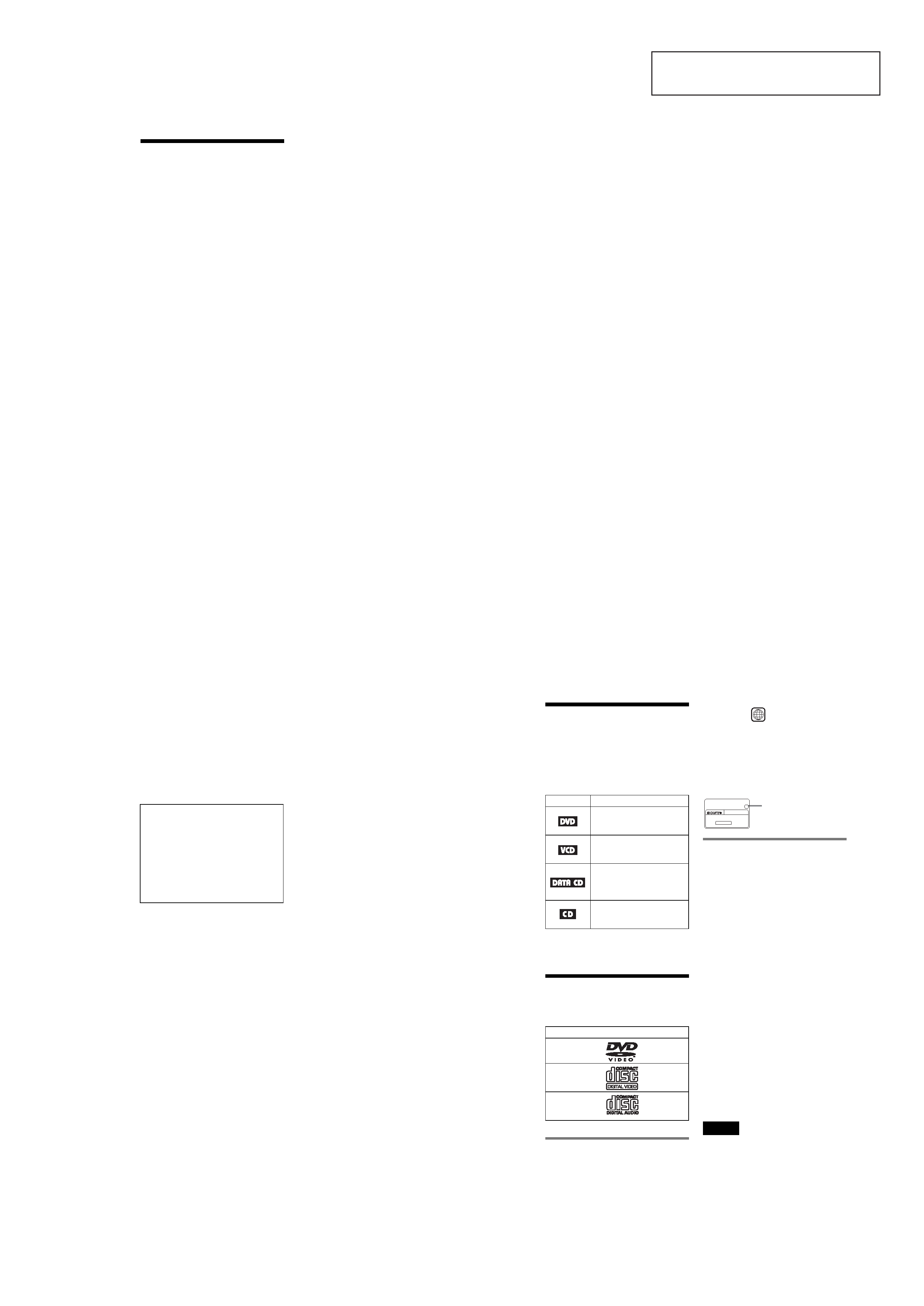
This Player Can Play the
Following Discs
The "DVD VIDEO" logo is a trademark.
Region code
Your player has a region code printed on the
bottom of the unit and only will play DVD
VIDEO discs (playback only) labeled with
identical region codes. This system is used to
protect copyrights.
DVDs labeled
will also play on this
player.
If you try to play any other DVD, the message
"Playback prohibited by area limitations."
will appear on the TV screen. Depending on
the DVD, no region code indication may be
labeled even though playing the DVD is
prohibited by area restrictions.
Example of discs that the player
cannot play
The player cannot play the following discs:
· All CD-ROMs (including PHOTO CDs)/
CD-Rs/CD-RWs other than those recorded
in the following formats:
music CD format
video CD format
MP3 format that conforms to ISO9660*
Level 1/Level 2, or its extended format,
Joliet
· Data part of CD-Extras
· DVD-RWs in VR mode
· DVD-ROMs
· DVD Audio discs
· HD layer on Super Audio CDs
* A logical format of files and folders on CD-
ROMs defined by ISO (International Standard
Organization).
Also, the player cannot play the following
discs:
· A DVD with a different region code.
· A disc that has a non-standard shape (e.g.,
card, heart).
· A disc with paper or stickers on it.
· A disc that has the adhesive of cellophane
tape or a sticker still left on it.
Note
Some CD-Rs, CD-RWs, DVD-Rs, or DVD-RWs
(in video mode) cannot be played on this player due
to the recording quality or physical condition of the
disc, or the characteristics of the recording device.
Furthermore, the disc will not play if it has not been
correctly finalized. For more information, see the
operating instructions for the recording device.
Icon
Meaning
Functions available for DVD
VIDEOs or DVD-Rs/DVD-
RWs in video mode
Functions available for VIDEO
CDs or CD-Rs/CD-RWs in
video CD format
Functions available for DATA
CDs (CD-ROMs/CD-Rs/CD-
RWs containing MP3* audio
tracks)
Functions available for music
CDs or CD-Rs/CD-RWs in
music CD format
Format of discs
DVD VIDEO
VIDEO CD
Music CD
ALL
DVPXXXX
00V 00Hz
00W
NO.
0-000-000-00
X
Region code
c continued