DVP-F21
RMT-D137A/RMT-D137P
SERVICE MANUAL
US Model
Canadian Model
AEP Model
UK Model
Mexico Model
Hong Kong Model
Singapore Model
SPECIFICATIONS
CD/DVD PLAYER
Specifications
System
Laser
Semiconductor laser
Signal format system
NTSC (EXCEPT AEP, UK)
PAL (AEP, UK)
Audio characteristics
Frequency response
DVD (PCM 96 kHz): 2 Hz to 44 kHz (
±1.0 dB)
DVD (PCM 48 kHz): 2 Hz to 22 kHz (
±0.5 dB)
CD: 2 Hz to 20 kHz (
±0.5 dB)
Signal-to-noise ratio (S/N ratio)
115 dB (AUDIO OUT L/R jacks only)
Harmonic distortion
0.003%
Dynamic range
DVD: 103 dB
CD: 99 dB
Wow and flutter
Less than detected value (
±0.001% W PEAK)
The signals from AUDIO OUT L/R jacks are measured. When you play PCM sound tracks with a 96 kHz sampling
frequency, the output signal from the DIGITAL OUT (OPTICAL) jack is converted to 48 kHz sampling frequency.
Outputs
General
Power requirements
DC 10.5 V
See page 3 for further information.
Power consumption
12 W
Dimensions (approx.)
252
× 60 × 183 mm (10 × 2 3/8 × 7 1/4 in.) (width/height/depth)
including projecting parts
Mass (approx.)
1.5 kg (3 lb 5 oz)
Operating temperature
5
°C to 35°C (41°F to 95°F)
Operating humidity
25% to 80%
Jack name
Jack type
Maximum output
level
Load impedance
DIGITAL OUT
(OPTICAL)
Optical output jack
-18 dBm
Wave length 660 nm
AUDIO OUT L/R
Phono jack
2 Vrms (50 kilohms)
Over 10 kilohms
VIDEO OUT
Phono jack
1.0 Vp-p
75 ohms, sync negative
S-VIDEO OUT
4-pin mini DIN
Luminance signal:
1.0 Vp-p
Color signal:
0.286 Vp-p (NTSC)
0.3 Vp-p (PAL)
75 ohms, sync negative
75 ohms terminated
Supp
AC power adaptor
Mo
· Audio/video cord (pinplug
× 3 pinplug × 3) (1)
· Remote commander (remote) RMT-D137A (1) (US, CND, MX)
RMT-D137P (1) (EXCEPT US, CND, MX)
· Size AA (R6) batteries (2)
· AC power adaptor AC-F21 (1)
· AC power cord (1)
· Jack cover for vertical installation (1)
del name
AC-F21
Power requirements
100 to 240 V AC, 50/60 Hz
Output voltage
DC 10.5 V, 1.3 A in operating mode
Operating temperature
5
°C to 35°C (41°F to 95°F)
Storage temperature
20
°C to 60°C (4°F to 140°F)
lied accessories
Optional accessory
Active Speaker System SA-F21
Specifications and design are subject to change without notice.
ENERGY STAR
is a U.S. registered mark. As an ENERGY STAR Partner, Sony Corporation has determined
that this product meets the
ENERGY STAR
guidelines for energy efficiency.
2
SAFETY CHECK-OUT
After correcting the original service problem, perform the following
safety checks before releasing the set to the customer:
1. Check the area of your repair for unsoldered or poorly-sol-dered
connections. Check the entire board surface for solder splashes
and bridges.
2. Check the interboard wiring to ensure that no wires are "pinched"
or contact high-wattage resistors.
3. Look for unauthorized replacement parts, particularly transis-
tors, that were installed during a previous repair. Point them out
to the customer and recommend their replacement.
4. Look for parts which, though functioning, show obvious signs
of deterioration. Point them out to the customer and recom-
mend their replacement.
5. Check the line cord for cracks and abrasion. Recommend the
replacement of any such line cord to the customer.
6. Check the B+ voltage to see it is at the values specified.
7. Check the antenna terminals, metal trim, "metallized" knobs,
screws, and all other exposed metal parts for AC leakage.
Check leakage as described below.
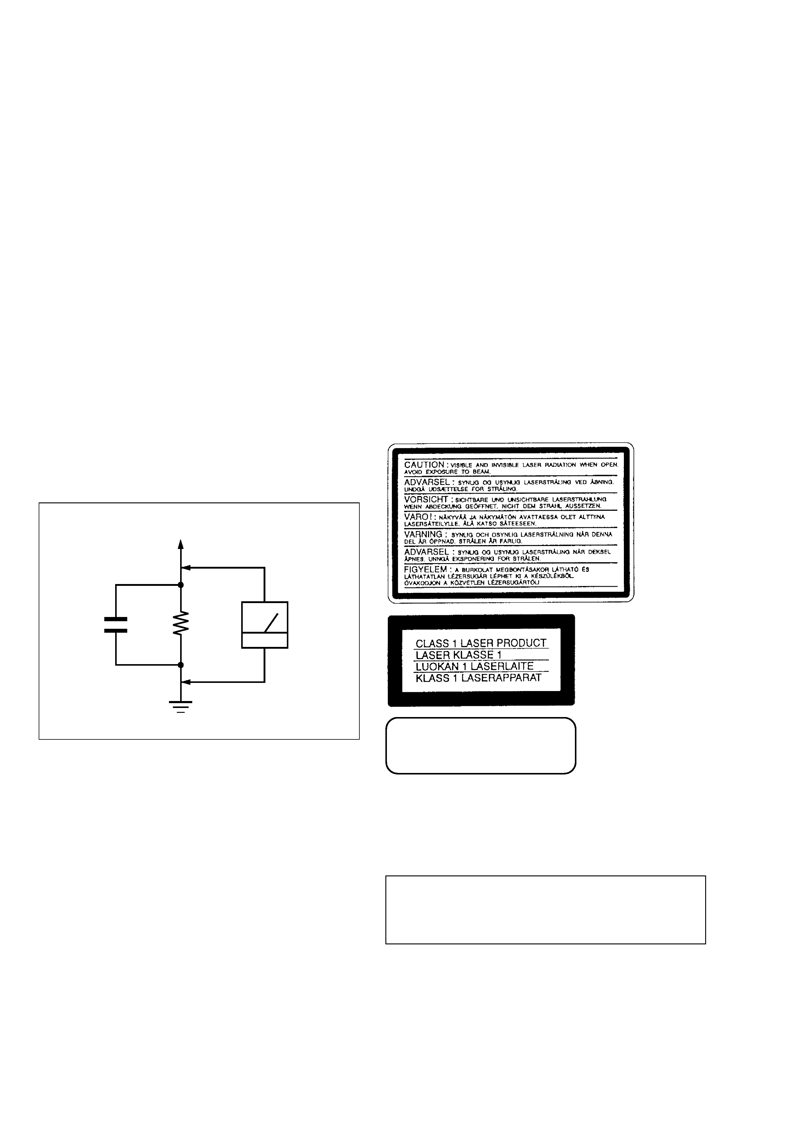
LEAKAGE TEST
The AC leakage from any exposed metal part to earth ground and
from all exposed metal parts to any exposed metal part having a
return to chassis, must not exceed 0.5 mA (500 microamperes).
Leakage current can be measured by any one of three methods.
1. A commercial leakage tester, such as the Simpson 229 or RCA
WT-540A. Follow the manufacturers' instructions to use these
instruments.
2. A battery-operated AC milliammeter. The Data Precision 245
digital multimeter is suitable for this job.
3. Measuring the voltage drop across a resistor by means of a VOM
or battery-operated AC voltmeter. The "limit" indica-tion is
0.75V, so analog meters must have an accurate low-voltage scale.
The Simpson 250 and Sanwa SH-63Trd are ex-amples of a pas-
sive VOM that is suitable. Nearly all battery operated digital
multimeters that have a 2V AC range are suit-able. (See Fig. A)
WARNING!!
WHEN SERVICING, DO NOT APPROACHTHE LASER EXIT
WITHTHE EYE TOO CLOSELY. IN CASE IT IS NECESSARY
TO CONFIRM LASER BEAM EMISSION, BE SURE TO
OBSERVE FROM A DISTANCE OF MORE THAN 25 cm
FROM THE SURFACE OF THE OBJECTIVE LENS ON THE
OPTICAL PICK-UP BLOCK.
ATTENTION AU COMPOSANT AYANT RAPPORT
À LA SÉCURITÉ!
LES COMPOSANTS IDENTIFIÉS PAR UNE MARQUE !
!
!
!
! SUR LES
DIAGRAMMES SCHÉMATIQUES ET LA LISTE DES PIÈCES SONT
CRITIQUES POUR LA SÉCURITÉ DE FONCTIONNEMENT. NE
REMPLACER CES COM-POSANTS QUE PAR DES PIÈCES SONY
DONT LES NUMÉROS SONT DONNÉS DANS CE MANUEL OU
DANS LES SUPPLÉMENTS PUBLIÉS PAR SONY.
SAFETY-RELATED COMPONENT WARNING!!
COMPONENTS IDENTIFIED BY MARK !
!
!
!
! OR DOTTED LINE WITH
MARK 0 ON THE SCHEMATIC DIAGRAMS AND IN THE PARTS
LIST ARE CRITICAL TO SAFE OPERATION. REPLACE THESE
COMPONENTS WITH SONY PARTS WHOSE PART NUMBERS
APPEAR AS SHOWN IN THIS MANUAL OR IN SUPPLEMENTS
PUB-LISHED BY SONY.
CAUTION:
The use of optical instrument with this product will increase eye
hazard.
CLASS 3B LASER
LUOKAN 3B LASER
LASERKLASS 3B
CAUTION
Use of controls or adjustments or performance of procedures
other than those specified herein may result in hazardous ra-
diation exposure.
To Exposed Metal
Parts on Set
AC
voltmeter
(0.75 V)
Earth Ground
1.5 k
0.15
µF
Fig. A. Using an AC voltmeter to check AC leakage.

3
TABLE OF CONTENTS
Section
Title
Page
1.
GENERAL
2.
DISASSEMBLY
2-1.
Terminal Cover, Lower Case .......................................... 2-1
2-2.
Upper Case .................................................................... 2-1
2-3.
Mechanism Deck ............................................................ 2-1
2-4.
Chucking Arm Block ....................................................... 2-1
2-5.
MD-90, Board, Lever Assembly ...................................... 2-2
2-6.
Base (C) Assembly ......................................................... 2-2
2-7.
Optical Device ................................................................ 2-2
2-8.
BU Holder ....................................................................... 2-2
2-9.
Gate Assembly, Cover (T) .............................................. 2-3
2-10.
Roller (Slider) ................................................................. 2-3
2-11.
Slider (L), Slider (R) ........................................................ 2-3
2-12.
FL-123 Board ................................................................. 2-3
2-13.
MB-99, IR-39 Boards ...................................................... 2-4
2-14.
Sliders (L) and (R) Phase Adjustment ............................ 2-4
2-15.
Internal Views ................................................................. 2-5
2-16.
Circuit Boards Location .................................................. 2-6
3.
BLOCK DIAGRAMS
3-1.
Overall Block Diagram .................................................... 3-1
3-2.
RF/SERVO Block Diagram ............................................. 3-3
3-3.
Signal Processor Block Diagram .................................... 3-5
3-4.
System Control Block Diagram ...................................... 3-7
3-5.
Video Block Diagram ...................................................... 3-9
3-6.
Audio Block Diagram .................................................... 3-10
3-7.
Interface Control Block Diagram ................................... 3-11
3-8.
Power Block Diagram ................................................... 3-12
4.
PRINTED WIRING BOARDS AND SCHEMATIC
DIAGRAMS
4-1.
Frame Schematic Diagram ............................................. 4-3
4-2.
Printed Wiring Boards and Schematic Diagrams ........... 4-5
· IR-39 (IR) Printed Wiring Boards and Schematic
Diagrams .................................................................... 4-5
· MB-99 (VIDEO/AUDIO/SIGNAL PROCESS/SERVO)
Printed Wiring Board .................................................. 4-7
· MB-99 (SYSTEM CONTROL) Schematic
Diagram .................................................................... 4-11
· MB-99 (RF SERVO) Schematic Diagram ................. 4-13
· MB-99 (SIGNAL PROCESS) Schematic Diagram ... 4-15
· MB-99 (SERVO) Schematic Diagram ....................... 4-17
· MB-99 (SIGNAL PROCESS) Schematic Diagram ... 4-19
· MB-99 (SIGNAL PROCESS) Schematic Diagram ... 4-21
· MB-99 (POWER) Schematic Diagram ...................... 4-23
· MB-99 (AV OUT) Schematic Diagram ...................... 4-25
· MB-99 (VIDEO) Schematic Diagram ........................ 4-27
· MB-99 (AUDIO) Schematic Diagram ........................ 4-29
· MB-99 (AVMS) Schematic Diagram ......................... 4-31
· MD-89 (FUNCTION SWITCH 1)
Printed Wiring Board and Schematic Diagram ......... 4-33
· FL-123 (INTERFACE CONTROL)
Printed Wiring Board ................................................ 4-35
· FL-123 (INTERFACE CONTROL)
Schematic Diagram .................................................. 4-37
· MD-90 (FUNCTION SWITCH) Printed Wiring Board
and Schematic Diagram ........................................... 4-39
· MD-91 (SWITCH) Printed Wiring Board and
Schematic Diagram .................................................. 4-39
Section
Title
Page
5.
IC PIN FUNCTION DESCRIPTION
5-1.
System Control PIN Function (MB-99 Board IC103) ...... 5-1
5-2.
System Control PIN Function (FL-123 Board IC403) ..... 5-2
6.
TEST MODE
6-1.
General Description ....................................................... 6-1
6-2.
Starting Test Mode ......................................................... 6-1
6-3.
Syscon Diagnosis ........................................................... 6-1
6-4.
Drive Auto Adjustment .................................................... 6-5
6-5.
Drive Manual Operation ................................................. 6-7
6-6.
Mecha Aging ................................................................ 6-10
6-7.
Emergency History ....................................................... 6-10
6-8.
Version Information ...................................................... 6-12
6-9.
Video Level Adjustment ................................................ 6-12
6-10.
IF CON Function Check Mode ..................................... 6-12
6-11.
Troubleshooting ............................................................ 6-15
7.
ELECTRICAL ADJUSTMENT
7-1.
Power Supply Check ...................................................... 7-1
1.
MB-99 Boards .......................................................... 7-1
7-2.
Adjustment of Video System .......................................... 7-2
1.
Video Level Adjustment (MB-99 Board) ................... 7-2
2.
Checking S Video Output S-Y .................................. 7-2
3.
Checking S Video Output S-C .................................. 7-2
7-3.
Adjustment Related Parts Arrangement ......................... 7-2
8.
REPAIR PARTS LIST
8-1.
Exploded Views .............................................................. 8-1
8-1-1.
Case Assembly ............................................................ 8-1
8-1-2.
MECH.DECK Block (1) ................................................ 8-2
8-1-3.
MECH.DECK Block (2) ................................................ 8-3
8-1-4.
CHASSIS Block ........................................................... 8-4
8-1-5.
Supplied Accessories .................................................. 8-5
8-2.
Electrical Parts List ......................................................... 8-6

1-1
DVP-F21
SECTION 1
GENERAL
7
About this Manual
· Instructions in this manual describe the
controls on the remote. You can also use the
controls on the player if they have the same
or similar names as those on the remote.
· The icons used in this manual are described
below:
This Player Can Play the
Following Discs
The "DVD VIDEO" logo is a trademark.
Region code
Your player has a region code printed on the
back of the unit and will only play DVDs
labeled with identical region codes.
DVDs labeled
will also play on this
player.
If you try to play any other DVD, the
message "Playback prohibited by area
limitations." will appear on the TV screen.
Depending on the DVD, no region code
indication may be labeled even though
playing the DVD is prohibited by area
restrictions.
Example of discs that the player
cannot play
The player cannot play the following discs:
· CD-ROMs (PHOTO CDs included)
· All CD-Rs/RWs other than music and VCD
format CD-Rs/RWs
· Data part of CD-Extras
· DVD-ROMs
· DVD Audio discs
· DVD-RWs recorded in video recording
format (VR mode)
· HD layer on SACDs
Also, the player cannot play the following
discs:
· A DVD with a different region code (page
78).
· A disc recorded in a color system other than
NTSC, such as PAL or SECAM. (This
player conforms to the NTSC color
system.)
· A disc that has a non-standard shape (e.g.,
card, heart).
· A disc with paper or stickers on it.
· A disc that has the adhesive of cellophane
tape or a sticker still left on it.
Icon
Meaning
Icon
Meaning
Functions
available in
DVD video
mode
Functions
available in
music CD
mode
Functions
available in
VIDEO CD
mode
z
More
convenient
features
Format of discs
ALL
Region Code
DVD VIDEO
VIDEO CD
Music CD
continued
8
Note
Some CD-Rs or CD-RWs cannot be played on this
player depending upon the recording quality or
physical condition of the disc, or the characteristics of
the recording device.
Furthermore, the disc will not play if it has not been
correctly finalized. For more information, see the
operating instructions for the recording device.
Note on playback operations of DVDs
and VIDEO CDs
Some playback operations of DVDs and
VIDEO CDs may be intentionally set by
software producers. Since this player plays
DVDs and VIDEO CDs according to the disc
contents the software producers designed,
some playback features may not be available.
Also, refer to the instructions supplied with
the DVDs or VIDEO CDs.
Copyrights
This product incorporates copyright
protection technology that is protected by
method claims of certain U.S. patents, other
intellectual property rights owned by
Macrovision Corporation, and other rights
owners. Use of this copyright protection
technology must be authorized by
Macrovision Corporation, and is intended for
home and other limited viewing uses only,
unless otherwise authorized by Macrovision
Corporation. Reverse engineering or
disassembly is prohibited.
Notes about the Discs
On handling discs
· To keep the disc clean, handle the disc by its
edge. Do not touch the surface.
· Do not expose the disc to direct sunlight or
heat sources such as hot air ducts, or leave
it in a car parked in direct sunlight as the
temperature may rise considerably inside
the car.
· After pressing
A on the player to eject the
disc, do no leave the disc as it is. Remove it
completely from the player.
· After playing, store the disc in its case.
· If glue is present on the outer edge of the
disc, wipe the edge of the disc with the side
of a pen or pencil so that the glue is spread
evenly along the edge before inserting the
disc into the player. Be sure not to touch the
playback side of the disc when wiping the
edge.
· If burrs remain on the outer edge of the
disc, remove them by rubbing with the side
of a pen or pencil. If burrs are not removed,
discs may not load properly into the player,
or fragments of plastic adhering to the
playback side of the disc may cause
skipping in the sound.
On cleaning
· Before playing, clean the disc with a
cleaning cloth. Wipe the disc from the
center out.
· Do not use solvents such as benzine,
thinner, commercially available cleaners, or
anti-static spray intended for vinyl LPs.
9
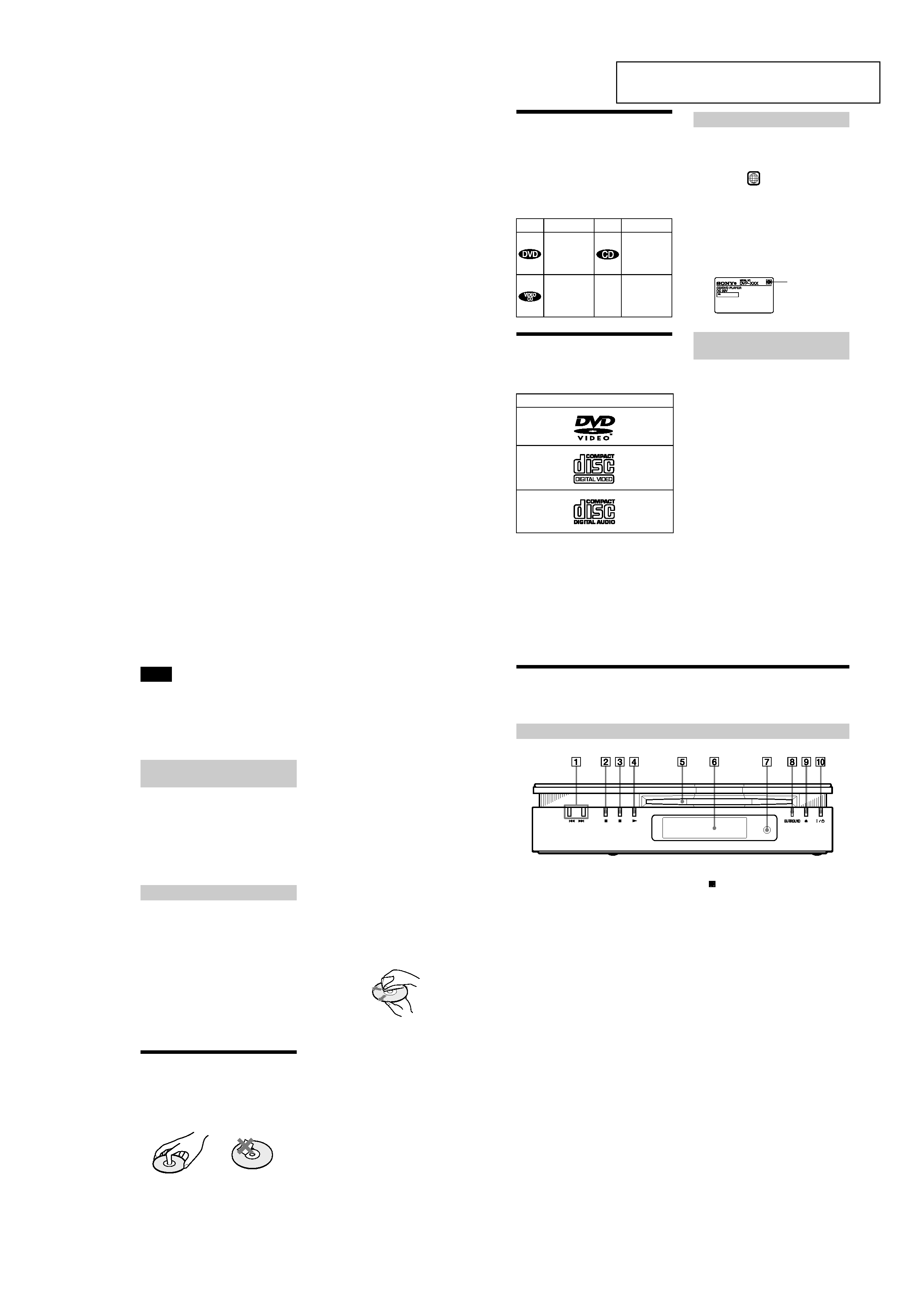
Index to Parts and Controls
For more information, refer to the pages indicated in parentheses.
Front Panel
A ./> (previous/next) buttons (37)
B x (stop) button (36)
C X (pause) button (37, 63)
D N (play) button (36)
E Disc slot (36)
F Front panel display (10)
G
(remote sensor) (15)
H SURROUND indicator (53)
I A (eject) button (37)
J ?/1 (power) button/indicator (36)
This section is extracted rom instruction
manual (3-070-343-11).