DVP-CX850D
RMT-D113P
AEP Model
UK Model
SERVICE MANUAL
CD/DVD PLAYER
MICROFILM
SPECIFICATIONS
CD/DVD player
Laser
Semiconductor laser
Signal format system
PAL/(NTSC)
Audio characteristics
Frequency response
DVD (PCM 96 kHz): 2 Hz to 44 kHz
(
±1 dB)*
DVD (PCM 48 kHz): 2 Hz to 22 kHz
(
±0.5 dB)
CD: 2 Hz to 20 kHz (
±0.5 dB)
Signal-to-noise ratio
More than 110 dB (LINE OUTPUT (AUDIO)
connectors only)
Harmonic distortion
Less than 0.0025%
Dynamic range
More than 100 dB (DVD)
More than 98 dB (CD)
Wow and flutter
Less than detected value
(
±0.001% W PEAK)
Outputs and inputs
LINE OUTPUT
(AUDIO)
DIGITAL
OUTPUT
(OPTICAL)
DIGITAL
OUTPUT
(COAXIAL)
LINE OUTPUT
(VIDEO)
S VIDEO
OUTPUT
5.1CH
OUTPUT
MEGA
CONTROL
AUDIO INPUT
General
Power requirements (indicated on the rear panel)
220 240 V AC, 50/60 Hz
Power consumption
20 W
Dimensions (approx.)
430
× 198 × 503 mm (w/h/d)
incl. projecting parts
Mass (approx.)
10 kg
Operating temperature
5 °C to 35 °C
Operating humidity
25 % to 80 %
Supplied accessories
* The signals from LINE OUTPUT (AUDIO) connectors and 5.1 ch L,
R connectors are measured. When you play the PCM sound tracks
with 96 kHz sampling frequency, the output signals from the
DIGITAL OUTPUT (OPTICAL, COAXIAL) are converted to 48
kHz (sampling frequency).
Design and specifications are subject to change without notice.
Jack
type
Phono
jacks
Optical
output
connector
Phono
jack
Phono
jacks
4-pin
mini DIN
Phono
jacks
Mini jack
Phono
jack
Output/Input
level
2 Vrms
(at 50 kilohms)
18 dBm
0.5 Vp-p
1.0 Vp-p
Y: 1.0 Vp-p
C: 0.3 Vp-p
(PAL)
0.286 Vp-p
(NTSC)
2 Vrms
(at 50 kilohms)
2 Vrms
Load impedance
Over 10 kilohms
Wave length: 660 nm
75 ohms terminated
75 ohms,
sync negative
75 ohms,
sync negative
75 ohms terminated
Over 10 kilohms
47 kilohms
· Audio/video connecting cord (1)
· S video cord (1)
· Remote commander (remote) RMT-D113P (1)
· R6 (Size AA) batteries (2)

-- 2 --
SAFETY CHECK-OUT
After correcting the original service problem, perform the following
safety checks before releasing the set to the customer.
1.
Check the area of your repair for unsoldered or poorly-soldered
connections. Check the entire board surface for solder splashes
and bridges.
2.
Check the interboard wiring to ensure that no wires are
"pinched" or contact high-wattage resistors.
3.
Look for unauthorized replacement parts, particularly
transistors, that were installed during a previous repair. Point
them out to the customer and recommend their replacement.
SAFETY-RELATED COMPONENT WARNING!!
COMPONENTS IDENTIFIED BY MARK 0 OR DOTTED LINE WITH
MARK
! ON THE SCHEMATIC DIAGRAMS AND IN THE PARTS
LIST ARE CRITICAL TO SAFE OPERATION. REPLACE THESE
COMPONENTS WITH SONY PARTS WHOSE PART NUMBERS
APPEAR AS SHOWN IN THIS MANUAL OR IN SUPPLEMENTS
PUBLISHED BY SONY.
4.
Look for parts which, though functioning, show obvious signs
of deterioration. Point them out to the customer and
recommend their replacement.
5.
Check the B+ voltage to see it is at the values specified.
6.
Flexible Circuit Board Repairing
· Keep the temperature of the soldering iron around 270°C
during repairing.
· Do not touch the soldering iron on the same conductor of the
circuit board (within 3 times).
· Be careful not to apply force on the conductor when soldering
or unsoldering.
CAUTION
Use of controls or adjustments or performance of procedures
other than those specified herein may result in hazardous radiation
exposure.
WARNING!!
WHEN SERVICING, DO NOT APPROACH THE LASER EXIT WITH
THE EYE TOO CLOSELY. IN CASE IT IS NECESSARY TO
CONFIRM LASER BEAM EMISSION, BE SURE TO OBSERVE
FROM A DISTANCE OF MORE THAN 25 cm FROM THE SURFACE
OF THE OBJECTIVE LENS ON THE OPTICAL PICK-UP BLOCK.
CAUTION:
The use of optical instrument with this product will increase eye
hazard.

-- 3 --
TABLE OF CONTENTS
SERVICE NOTE ····································································· 5
SELF-DIAGNOSIS FUNCTION
1.
FRONT BOARD TEST MODE ········································· 6
2.
HOW TO ENTER THE TEST MODE ······························· 6
3.
HOW TO EXIT THE TEST MODE ·································· 6
DETAILED DESCRIPTION OF THE
FRONT BOARD TEST
1.
TESTING THE BUTTON FUNCTION ···························· 7
2.
TESTING THE REMOTE COMMANDER
SIGNAL RECEPTION FUNCTION ································· 7
3.
TESTING THE SYSTEM CONTROLLER
IF CONTROLLER SERIAL COMMUNICATION
FUNCTION ········································································ 7
4.
TESTING THE CLICK SHUTTLE FUNCTION ·············· 7
5.
TESTING THE FL DISPLAY TUBE
ILLUMINATION CHECK ················································· 7
5-1.
FL Display Tube for DVP-CX850D ··································· 8
5-2.
Grid Check ········································································· 9
5-3.
Anode Check ······································································ 9
6.
TESTING THE LED CONTROL FUNCTION ················· 9
7.
TESTING THE KEY BOARD CONTROL FUNCTION ·· 9
8.
TROUBLESHOOTING ····················································· 9
8-1.
Cannot Enter the Test Mode ··············································· 9
8-2.
The Main Power Cannot Be Turned On ····························· 9
9.
FLD AUTO TEST OPERATION ···································· 10
1.
GENERAL
About This Manual ································································ 1-1
This Player Can Play the Following Discs ···························· 1-1
Precautions ············································································· 1-1
Notes on Discs ······································································· 1-1
Getting Started
Unpacking ·············································································· 1-1
TV Hookups ·········································································· 1-2
Receiver (Amplifier) Hookups ·············································· 1-2
5.1 Channel Surround Hookups ············································· 1-3
Selecting the Language for On-Screen Display ····················· 1-4
Inserting Discs ······································································· 1-4
Playing Discs
Playing Discs ········································································· 1-4
Playing at Various Speeds/Frame by Frame ·························· 1-5
Resuming Playback from the Point Where
You Stopped the Disc (Resume Play) ···································· 1-5
Using the Menu for Each DVD ············································· 1-5
Playing VIDEO CDs with
PBC Functions (PBC Playback) ············································ 1-6
Using the Front Panel Display ··············································· 1-6
Displaying the Disc Information (Disc Browser) ·················· 1-6
Filing Discs in the Folder ······················································ 1-7
Labeling Discs (Disc Memo)/Folders and
Indicating the Genre ······························································ 1-7
Sorting Discs ·········································································· 1-8
Using Various Functions with the Control Menu
Using the Control Menu Display ··········································· 1-8
Control Menu Item List ························································· 1-9
Seaching for the Disc/Title/Chapter/Track/Index/Scene ······· 1-9
Checking the Playing Time and Remaining Time ················· 1-9
Selecting a Start Point Using the Time Code ························ 1-9
Checking the Information of the Disc ································· 1-10
Changing the Sounds ··························································· 1-10
Displaying the Subtitles ······················································· 1-10
Changing the Angles ···························································· 1-10
Selecting the Disc Mode (1 Disc or All Discs) ···················· 1-10
Creating Your Own Program (Program Play) ······················ 1-11
Playing in Random Order (Shuffle Play) ····························· 1-11
Playing Repeatedly (Repeat Play) ······································· 1-11
Repeating a Specific Portion (A
B Rrepeat) ···················1-12
Setting for Digital Cinema Sound ······································· 1-12
Reducing the Picture Noise
(DNR: Digital Video Noise Reduction) ······························· 1-13
Adjustments for Playback Picture
(VIDEO EQ: Video Equalizer) ············································ 1-13
Displaying Different Angles Simultaneously ······················ 1-13
Dividing a Track into 9 Sections (Strobe Play) ··················· 1-13
Scanning the Title, Chapter and Track ································· 1-13
Setting and Selecting Favorite Scene (Bookmark) ·············· 1-13
Checking the Play Information ············································ 1-14
Setting and Adjustments
Using the Setup Display ······················································ 1-14
Setup Display Item List ······················································· 1-14
Setting the Language for Display and Sound
(LANGUAGE SETUP) ······················································· 1-15
Settings for Display (SCREEN SETUP) ····························· 1-15
Custom Settings (CUSTOM SETUP) ································· 1-15
Setting for Sound (AUDIO SETUP) ···································· 1-16
Speaker Set Up ···································································· 1-17
Controlling the TV or the AV Receiver (Amplifier)
with the Supplied Remote ···················································· 1-17
Controlling the CD Changer (Mega Control) ······················ 1-18
Additional Information
Troubleshooting ··································································· 1-18
Self-diagnosis function ························································ 1-19
Glossary ··············································································· 1-19
Language Code List ····························································· 1-20
Index to Parts and Controls ·················································· 1-20
2.
DISASSEMBLY
2-1.
FRONT PANEL ······························································ 2-1
2-2.
REAR PANEL, PLATE JACK ········································ 2-1
2-3.
TABLE 200 ASSEMBLY ················································ 2-2
2-4.
MECHANISM DECK ····················································· 2-3
2-5.
BASE UNIT ···································································· 2-3
2-6.
INTERNAL VIEWS ························································ 2-4
2-7.
CIRCUIT BOARDS LOCATION ··································· 2-5
3.
BLOCK DIAGRAMS
3-1.
OVERALL BLOCK DIAGRAM ···································· 3-1
3-2.
RF/SERVO BLOCK DIAGRAM ···································· 3-3
3-3.
SIGNAL PROCESS BLOCK DIAGRAM ······················ 3-5
3-4.
VIDEO BLOCK DIAGRAM ·········································· 3-7
3-5.
SYSTEM CONTROL BLOCK DIAGRAM ··················· 3-9
3-6.
AUDIO BLOCK DIAGRAM-1 ···································· 3-11
3-7.
AUDIO BLOCK DIAGRAM-2 ···································· 3-13
3-8.
INTERFACE CONTROL BLOCK DIAGRAM ··········· 3-15
3-9.
POWER BLOCK DIAGRAM ······································· 3-17
4.
PRINTED WIRING BOARDS AND
SCHEMATIC DIAGRAMS
4-1.
FRAME SCHEMATIC DIAGRAM ································ 4-3
4-2.
PRINTED WIRING BOARDS AND
SCHEMATIC DIAGRAMS ············································ 4-7
· TK-54 (RF/SERVO)
PRINTED WIRING BOARD ························· 4-8
· TK-54 (RF/SERVO)
SCHEMATIC DIAGRAM ······························ 4-9
· MB-85 (SIGNAL PROCESS/SERVO)
PRINTED WIRING BOARD ······················· 4-11
· MB-85 (INTER FACE)
SCHEMATIC DIAGRAM ···························· 4-15
· MB-85 (SYSTEM CONTROL)
SCHEMATIC DIAGRAM ···························· 4-17

-- 4 --
· MB-85 (ARP)
SCHEMATIC DIAGRAM ···························· 4-19
· MB-85 (AV DECODER)
SCHEMATIC DIAGRAM ···························· 4-21
· MB-85 (AUDIO DSP, V EQ/NR)
SCHEMATIC DIAGRAM ···························· 4-23
· MB-85 (HGA)
SCHEMATIC DIAGRAM ···························· 4-25
· MB-85 (SERVO DSP)
SCHEMATIC DIAGRAM ···························· 4-27
· MB-85 (DRIVE)
SCHEMATIC DIAGRAM ···························· 4-29
· MB-85 (DAC)
SCHEMATIC DIAGRAM ···························· 4-31
· ER-10 (EURO AV)
SCHEMATIC DIAGRAM ···························· 4-33
· ER-10 (EURO AV)
PRINTED WIRING BOARD ······················· 4-35
· AU-225 (AUDIO)
PRINTED WIRING BOARD ······················· 4-39
· AU-225 (LPF AMP)
SCHEMATIC DIAGRAM ···························· 4-43
· AU-225 (VIDEO AMP)
SCHEMATIC DIAGRAM ···························· 4-45
· CK-82 (MOTOR DRIVE)
PRINTED WIRING BOARD ······················· 4-47
· CK-82 (MOTOR DRIVE)
SCHEMATIC DIAGRAM ···························· 4-49
· TS-150 (TABLE SENSOR), SI-25 (SI SENSOR),
SO-12 (SO LED)
PRINTED WIRING BOARDS ····················· 4-51
· TS-150 (TABLE SENSOR), SI-25 (SI SENSOR),
SO-12 (SO LED)
SCHEMATIC DIAGRAMS ·························· 4-53
· LT-35 (TABLE LED), TM-127 (TABLE MOTOR),
DS-93 (DOOR SWITCH), LS-54 (CHACK SENSOR),
LM-60 (LOADING MOTOR)
PRINTED WIRING BOARDS ····················· 4-55
· LT-35 (TABLE LED), TM-127 (TABLE MOTOR),
DS-93 (DOOR SWITCH), LS-54 (CHACK SENSOR),
LM-60 (LOADING MOTOR)
SCHEMATIC DIAGRAMS ·························· 4-57
· FL-105 (FUNCTION SWITCH)
PRINTED WIRING BOARD ······················· 4-59
· FL-105 (DC-DC CONVERTER)
SCHEMATIC DIAGRAM ···························· 4-63
· FL-105 (DISPLAY CONTORL)
SCHEMATIC DIAGRAM ···························· 4-65
· SW-335 (SURROUND SWITCH), LE-26 (MULTI LED)
PRINTED WIRING BOARDS ····················· 4-67
· SW-335 (SURROUND SWITCH), LE-26 (MULTI LED)
SCHEMATIC DIAGRAMS ·························· 4-69
· FR-168 (IR/POWER SWITCH),
KB-37 (KEY BOARD JACK)
PRINTED WIRING BOARDS ····················· 4-71
· FR-168 (IR/POWER SWITCH),
KB-37 (KEY BOARD JACK)
SCHEMATIC DIAGRAMS ·························· 4-73
· HS-030SH (SWITCHING REGULATOR)
PRINTED WIRING BOARD ······················· 4-75
· HS-030SH (SWITCHING REGULATOR)
SCHEMATIC DIAGRAM ···························· 4-77
5.
IC PIN FUNCTION DESCRIPTION
5-1.
SYSTEM CONTROL PIN FUNCTION
(MB-85 BOARD IC202) ················································· 5-1
6.
TEST MODE
6-1.
GENERAL DESCRIPTION ··········································· 6-1
6-2.
STARTING TEST MODE ··············································· 6-1
6-3.
SYSCON DIAGNOSIS ··················································· 6-1
6-4.
DRIVE AUTO ADJUSTMENT ······································ 6-5
6-5.
DRIVE MANUAL OPERATION ··································· 6-7
6-6.
MECHA AGING ····························································· 6-9
6-7.
EMERGENCY HISTORY ············································ 6-10
6-8.
VERSION INFORMATION ········································· 6-11
6-9.
VIDEO LEVEL ADJUSTMENT ·································· 6-11
7.
MECHANICAL ADJUSTMENTS
7-1.
TS-150 BOARD POSITION ADJUSTMENT ················ 7-1
7-2.
SO-12 BOARD POSITION ADJUSTMENT ················· 7-2
7-3.
DISC SENSOR LEVEL ADJUSTMENT ······················· 7-2
7-4.
DISC/TABLE SENSOR CHECK ··································· 7-2
7-5.
HOLDER (DISC A) ADJUSTMENT ····························· 7-3
7-6.
GUIDE (DISC T) ADJUSTMENT ································· 7-4
7-7.
DISC PULLY ADJUSTMENT ······································· 7-5
7-8.
MAGNET ASSEMBLY ADJUSTMENT ······················· 7-6
8.
ELECTRICAL ADJUSTMENT
8-1.
POWER SUPPLY ADJUSTMENT ································· 8-1
1.
HS-030SH Board ····························································· 8-1
8-2.
ADJUSTMENT OF VIDEO SYSTEM ··························· 8-2
1.
Video Level Adjustment (MB-85 BOARD) ···················· 8-2
2.
S-terminal Output Check (MB-85 BOARD) ··················· 8-2
3.
Checking Component Video Output B-Y
(MB-85 BOARD) ···························································· 8-2
4.
Checking Component Video Output R-Y
(MB-85 BOARD) ··························································· 8-2
5.
Checking Component Video Output Y
(MB-85 BOARD) ···························································· 8-3
6.
Checking S Video Output S-C (MB-85 BOARD) ··········· 8-3
7.
Cheking EURO AV1 RGB Output ·································· 8-3
8.
Checking EURO AV1 YC Output ···································· 8-3
9.
Checking EURO AV1, 2 VIDEO Output ························· 8-4
8-3.
ADJUSTMENT RELATED PARTS
ARRANGEMENT ·························································· 8-5
9.
REPAIR PARTS LIST
9-1.
EXPLODED VIEWS ······················································ 9-1
9-1-1. CASE AND REAR PANEL SECTION ·························· 9-1
9-1-2. DISC TABLE SECTION ················································· 9-2
9-1-3. FRONT PANEL SECTION-1 ········································· 9-3
9-1-4. FRONT PANEL SECTION-2 ········································· 9-4
9-1-5. MECHANISM DECK SECTION-1 ······························· 9-5
9-1-6. MECHANISM DECK SECTION-2 ······························· 9-6
9-1-7. MECHANISM DECK SECTION-3 ······························· 9-7
9-2.
ELECTRICAL PARTS LIST ·········································· 9-8
-- 5 --
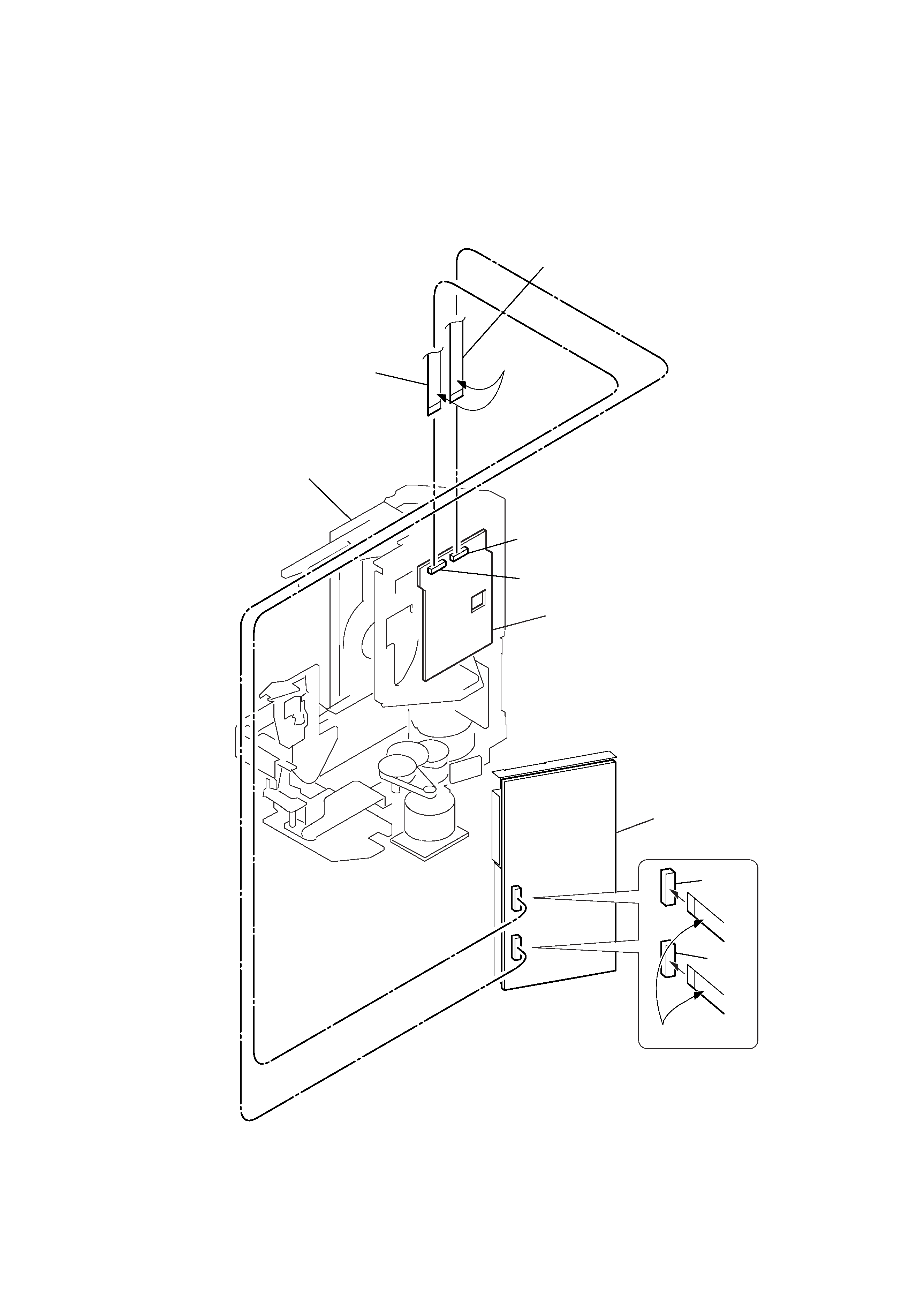
SERVICE NOTE
· The two flat type wires that connect the TK-54 board with the MB-85 board are not equipped with the mis-insertion preventive measures.
If the two wires are incorrectly inserted each other by mistake, it can damage the MB-85 board as the secondary failure.
MB-85 board
Flat type wire
(18 core)
(from CN003 to CN004)
Flat type wire
(18 core)
(from CN002 to CN003)
Insulater side
Mechanism deck
CN003
CN004
TK-54 board
CN002
CN003
Insulater side