SERVICE MANUAL
CD/DVD PLAYER
US Model
Canadian Model
SPECIFICATIONS
DVP-CX777ES
Ver 1.1 2004.09
9-961-043-02
Sony Corporation
2004I05-1
Audio Group
C
2004.09
Published by Sony Engineering Corporation
Model Name Using Similar Mechanism NEW
CD/DVD Mechanism Type
CDM62-DVBU26
Base Unit Name
DVBU26
Optical Pick-up Name
KHM-290AAA
System
Laser: Semiconductor laser
= 780 nm for CD
= 650 nm for SA-CD and DVD
Emission duration: continuous
Signal format system: NTSC
Audio characteristics
Frequency response: DVD VIDEO (PCM
96 kHz): 2 Hz to 44 kHz (44 kHz: 2 dB
±1 dB), Super Audio CD: 2 Hz to
100 kHz (50kHz: 3dB ±1 dB), CD:
2Hz to 20 kHz (±0.5 dB)
Signal-to-noise ratio (S/N ratio): 115 dB
(LINE OUT AUDIO L/R 1/2 jacks only)
Harmonic distortion: 0.003 %
Dynamic range: DVD VIDEO/Super Audio
CD: 103 dB, CD: 99 dB
Wow and flutter: Less than detected value
(±0.001% W PEAK)
Outputs
(Jack name: Jack type/Output level/Load
impedance)
LINE OUT AUDIO L/R 1/2: Phono jack/
2Vrms/10 kilohms
DIGITAL OUT (OPTICAL): Optical
output jack/18 dBm (wave length:
660 nm)
DIGITAL OUT (COAXIAL): Phono jack/
0.5 Vp-p/75 ohms
5.1CH OUTPUT: Phono jack/2 Vrms/
10 kilohms
COMPONENT VIDEO OUT (Y, PB/CB,
PR/CR): Phono jack/Y: 1.0 Vp-p/PB/CB,
PR/CR: interlace*=0.648 Vp-p,
progressive or interlace**=0.7 Vp-p/
75 ohms
*BLACK LEVEL is ON
** BLACK LEVEL is OFF
LINE OUT VIDEO 1/2: Phono jack/
1.0 Vp-p/75 ohms
S VIDEO OUPUT 1/2: 4-pin mini DIN/
Y: 1.0 Vp-p/C: 0.286 Vp-p /75 ohms
S-LINK (CONTROL S IN): Mini jack
General
Power requirements:
120 V AC, 60 Hz
Power consumption: 24 W
Dimensions (approx.): 430
× 189 × 545 mm
(17
× 7 1/2 × 21 1/2 in.) (width/height/
depth) incl. projecting parts
Mass (approx.): 10 kg (22 lb 1 oz)
Operating temperature: 5
° C to 35 ° C
(41
° F to 95 ° F)
Operating humidity: 25 % to 80 %
Supplied accessories
Specifications and design are subject to
change without notice.
·Audio/video cord (pinplug
× 3 y pinplug
·Remote commander (remote) (1)
·Size AA (R6) batteries (2)
× 3) (1)
ENERGY STARR is a U.S. registered mark.
As an
ENERGY STARR Partner, Sony
Corporation has determined that this product
meets the
ENERGY STARR guidelines for
energy efficiency.
2
DVP-CX777ES
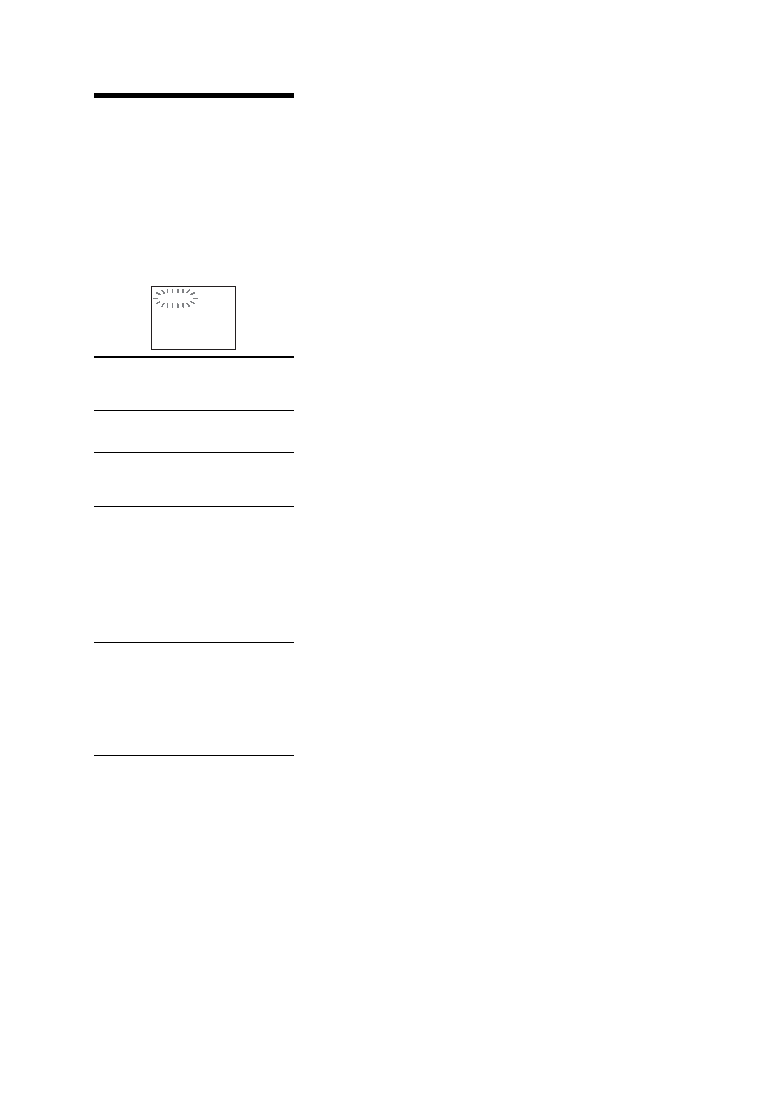
Self-diagnosis Function
(When letters/numbers appear in the
display)
When the self-diagnosis function is activated
to prevent the player from malfunctioning, a
five-character service number (e.g., C 13 50)
with a combination of a letter and four digits
appears on the screen and the front panel
display. In this case, check the following
table.
First three
characters of
the service
number
Cause and/or corrective
action
C 13
The disc is dirty.
, Clean the disc with a soft
cloth.
C 31
The disc is not inserted
correctly.
, Re-insert the disc
correctly.
C 32
The front cover
automatically opens and the
player enters standby mode.
, Check that there is
nothing wrong inside the
rotary table, such as a
fallen disc. After you
have checked the inside
of the rotary table and
resolved any possible
problems, press
H.
E XX
(xx is a number)
To prevent a malfunction, the
player has performed the
self-diagnosis function.
, Contact your nearest
Sony dealer or local
authorized Sony service
facility and give the 5-
character service number.
Example: E 61 10
C:13:50
Note: Refer to the "4. TEST MODE" (page 23)
for another self-diagnosis function.
SELF DIAGNOSIS FUNCTION
3
DVP-CX777ES
CAUTION
Use of controls or adjustments or performance of procedures
other than those specified herein may result in hazardous ra-
diation exposure.
Notes on chip component replacement
·Never reuse a disconnected chip component.
· Notice that the minus side of a tantalum capacitor may be dam-
aged by heat.
Flexible Circuit Board Repairing
·Keep the temperature of the soldering iron around 270 °C dur-
ing repairing.
· Do not touch the soldering iron on the same conductor of the
circuit board (within 3 times).
· Be careful not to apply force on the conductor when soldering
or unsoldering.
SAFETY CHECK-OUT
After correcting the original service problem, perform the follow-
ing safety check before releasing the set to the customer:
Check the antenna terminals, metal trim, "metallized" knobs,
screws, and all other exposed metal parts for AC leakage.
Check leakage as described below.
LEAKAGE TEST
The AC leakage from any exposed metal part to earth ground and
from all exposed metal parts to any exposed metal part having a
return to chassis, must not exceed 0.5 mA (500 microamperes.).
Leakage current can be measured by any one of three methods.
1. A commercial leakage tester, such as the Simpson 229 or RCA
WT-540A. Follow the manufacturers' instructions to use these
instruments.
2. A battery-operated AC milliammeter. The Data Precision 245
digital multimeter is suitable for this job.
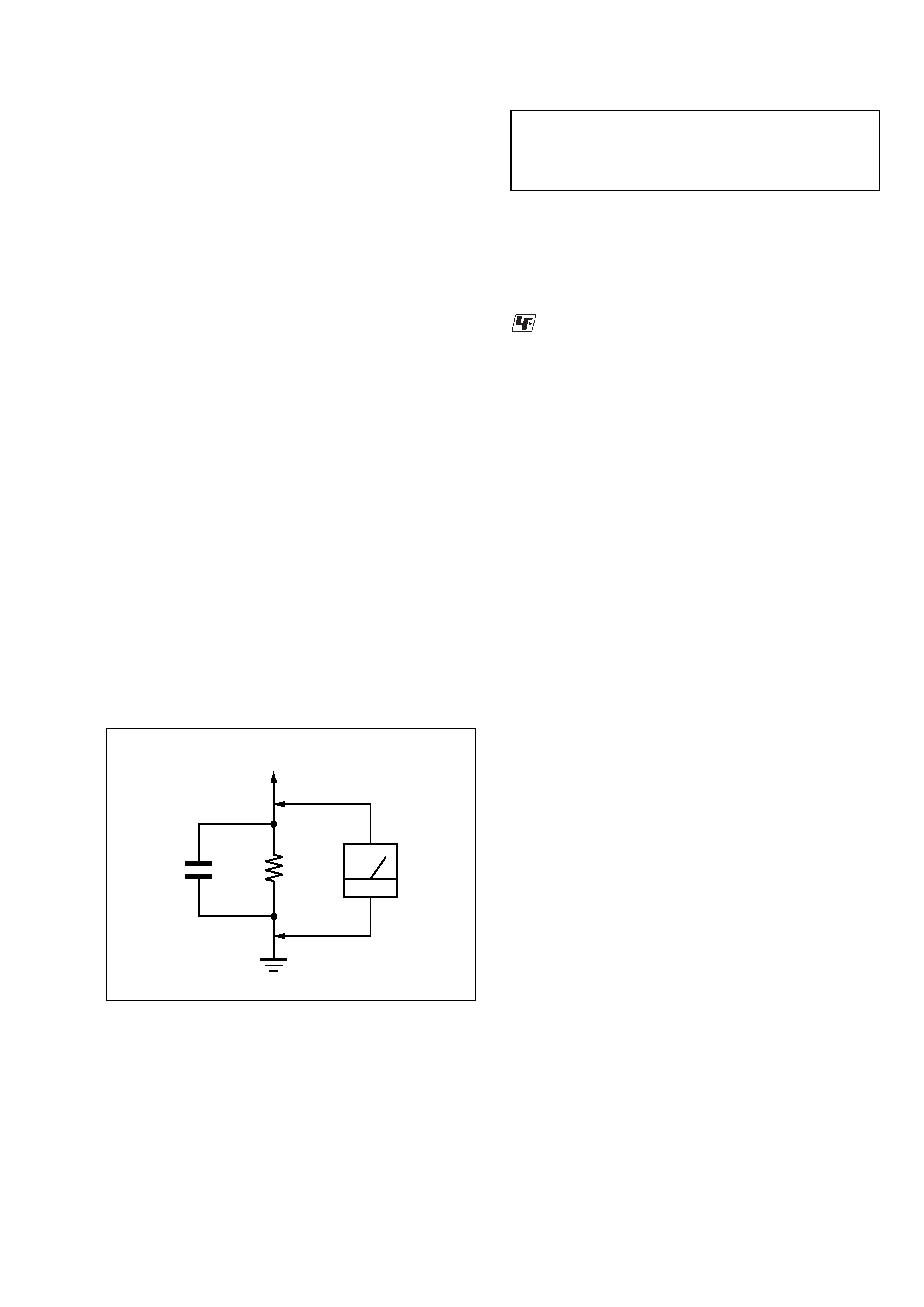
3. Measuring the voltage drop across a resistor by means of a VOM
or battery-operated AC voltmeter. The "limit" indication is 0.75
V, so analog meters must have an accurate low-voltage scale.
The Simpson 250 and Sanwa SH-63Trd are examples of a pas-
sive VOM that is suitable. Nearly all battery operated digital
multimeters that have a 2 V AC range are suitable. (See Fig. A)
Fig. A.
Using an AC voltmeter to check AC leakage.
1.5 k
0.15
µF
AC
voltmeter
(0.75 V)
To Exposed Metal
Parts on Set
Earth Ground
ATTENTION AU COMPOSANT AYANT RAPPORT
À LA SÉCURITÉ!
LES COMPOSANTS IDENTIFIÉS PAR UNE MARQUE 0
SUR LES DIAGRAMMES SCHÉMATIQUES ET LA LISTE
DES PIÈCES SONT CRITIQUES POUR LA SÉCURITÉ
DE FONCTIONNEMENT. NE REMPLACER CES COM-
POSANTS QUE PAR DES PIÈCES SONY DONT LES
NUMÉROS SONT DONNÉS DANS CE MANUEL OU
DANS LES SUPPLÉMENTS PUBLIÉS PAR SONY.
SAFETY-RELATED COMPONENT WARNING!!
COMPONENTS IDENTIFIED BY MARK 0 OR DOTTED
LINE WITH MARK 0 ON THE SCHEMATIC DIAGRAMS
AND IN THE PARTS LIST ARE CRITICAL TO SAFE
OPERATION. REPLACE THESE COMPONENTS WITH
SONY PARTS WHOSE PART NUMBERS APPEAR AS
SHOWN IN THIS MANUAL OR IN SUPPLEMENTS PUB-
LISHED BY SONY.
UNLEADED SOLDER
Boards requiring use of unleaded solder are printed with the lead-
free mark (LF) indicating the solder contains no lead.
(Caution: Some printed circuit boards may not come printed with
the lead free mark due to their particular size)
: LEAD FREE MARK
Unleaded solder has the following characteristics.
· Unleaded solder melts at a temperature about 40 °C higher than
ordinary solder.
Ordinary soldering irons can be used but the iron tip has to be
applied to the solder joint for a slightly longer time.
Soldering irons using a temperature regulator should be set to
about 350 °C.
Caution: The printed pattern (copper foil) may peel away if the
heated tip is applied for too long, so be careful!
· Strong viscosity
Unleaded solder is more viscou-s (sticky, less prone to flow)
than ordinary solder so use caution not to let solder bridges oc-
cur such as on IC pins, etc.
· Usable with ordinary solder
It is best to use only unleaded solder but unleaded solder may
also be added to ordinary solder.
4
DVP-CX777ES
Example of discs that the player
cannot play
The player cannot play the following discs:
·All CD-ROMs (including PHOTO CDs)/
CD-Rs/CD-RWs other than those recorded
in the following formats:
music CD format
video CD format
MP3 format that conforms to ISO9660*
Level 1/Level 2, or its extended format,
Joliet
·Data part of CD-Extras
· DVD-ROMs
· DVD Audios
*A logical format of files and folders on CD-
ROMs defined by ISO (International Standards
Organization).
Also, the player cannot play the following
discs:
·A DVD VIDEO with a different region
code.
·A disc recorded in a color system other than
NTSC, such as PAL or SECAM (this player
conforms to the NTSC color system).
·A disc that has a non-standard shape (e.g.,
card, heart).
·A disc with paper or stickers on it.
·A disc that has the adhesive of cellophane
tape or a sticker still left on it.
Notes
·Note about DVD-RWs/DVD-Rs, DVD+RWs/
DVD+Rs, or CD-Rs/CD-RWs.
Some DVD-RWs/DVD-Rs, DVD+RWs/
DVD+Rs, or CD-Rs/CD-RWs cannot be played
on this player due to the recording quality or
physical condition of the disc, or the
characteristics of the recording device and
authoring software. Also, images in DVD-RWs
with CPRM* protection may not be played if they
contain a copy protection signal. "Copyright
lock" appears on the screen. For more
information, see the operating instructions for the
recording device.
Note that discs created in the Packet Write format
cannot be played.
*CPRM (Content Protection for Recordable
Media) is a coding technology that protects
copyright for images.
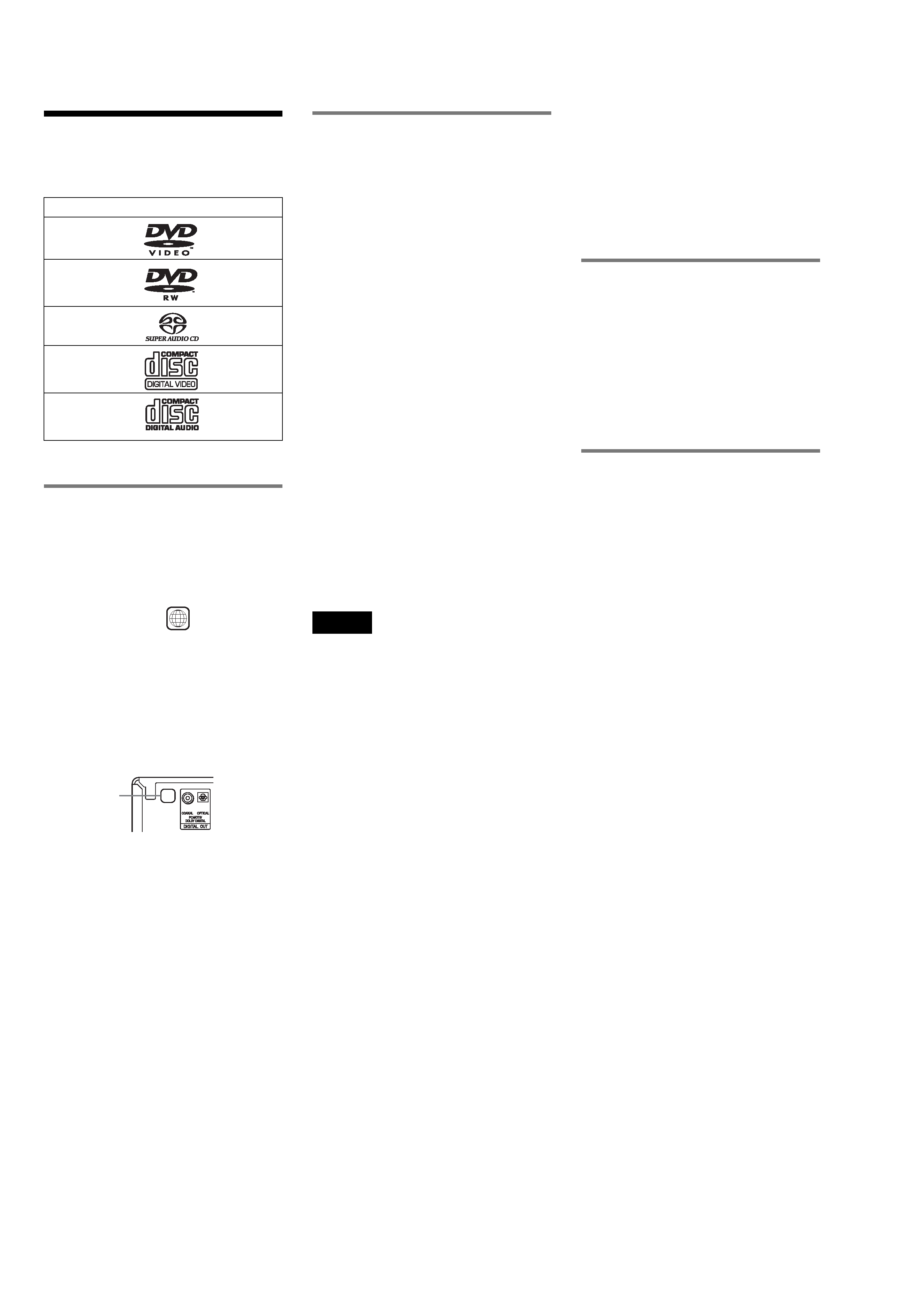
This Player Can Play the
Following Discs
"DVD VIDEO" and "DVD-RW" are
trademarks.
Region code
Your player has a region code printed on the
back of the unit and will only play DVD
VIDEOs (playback only) labeled with
identical region codes. This system is used to
protect copyrights.
DVD VIDEOs labeled
will also play on
this player.
If you try to play any other DVD VIDEO, the
message "Playback prohibited by area
limitations." will appear on the TV screen.
Depending on the DVD VIDEO, no region
code indication may be labeled even though
playing the DVD VIDEO is prohibited by
area restrictions.
Format of discs
DVD VIDEO
DVD-RW
Super Audio CD
VIDEO CD
Music CD
ALL
X
Region code
·Music discs encoded with copyright protection
technologies
This product is designed to playback discs that
conform to the Compact Disc (CD) standard.
Recently, various music discs encoded with
copyright protection technologies are marketed
by some record companies. Please be aware that
among those discs, there are some that do not
conform to the CD standard and may not be
playable by this product.
Note on playback operations of
DVDs and VIDEO CDs
Some playback operations of DVDs and
VIDEO CDs may be intentionally set by
software producers. Since this player plays
DVDs and VIDEO CDs according to the disc
contents the software producers designed,
some playback features may not be available.
Also, refer to the instructions supplied with
the DVDs or VIDEO CDs.
Copyrights
This product incorporates copyright
protection technology that is protected by
U.S. patents and other intellectual property
rights. Use of this copyright protection
technology must be authorized by
Macrovision, and is intended for home and
other limited viewing uses only unless
otherwise authorized by Macrovision.
Reverse engineering or disassembly is
prohibited.

5
DVP-CX777ES
SELF DIAGNOSIS FUNCTION ....................................
2
1.
SERVICING NOTES ............................................... 6
2.
GENERAL ................................................................... 10
3.
DISASSEMBLY
3-1. Disassembly Flow ........................................................... 11
3-2. Case (ES) Assy ................................................................ 12
3-3. MB Board ........................................................................ 12
3-4. AV Board ......................................................................... 13
3-5. Bracket (L)/(R) ................................................................ 13
3-6. Front Panel Section ......................................................... 14
3-7. Cover (PT)/(CDM) .......................................................... 14
3-8. DVBU26 Assy ................................................................. 15
3-9. Power Block, Power Transformer (T102) ...................... 15
3-10. Table (400) Assy ............................................................. 16
3-11. Door Block, Base (Door) Assy ....................................... 16
3-12. DC Motor (Door) (M603) ............................................... 17
3-13. Holder (Table Sensor 400) .............................................. 17
3-14. D. SENS OUT Board, D. SENS IN Board ..................... 18
3-15. Pop-up (400) Assy ........................................................... 18
3-16. Door SW Board ............................................................... 19
3-17. Lock SW Board, Loading SW Board ............................. 20
3-18. CD/DVD Mechanism Deck Block
(CDM62-DVBU26) ........................................................ 21
3-19. Motor (400) Assy (Loading) (M602)/(Table) (M601),
Loading Motor Board ..................................................... 21
3-20. Optical Pick-up (KHM-290AAA) .................................. 22
4.
TEST MODE .............................................................. 23
5.
MECHANICAL ADJUSTMENTS ....................... 45
6.
ELECTRICAL ADJUSTMENTS ......................... 46
7.
DIAGRAMS
7-1. Block Diagram RF Section ...................................... 50
7-2. Block Diagram SERVO/CHANGER Section ......... 51
7-3. Block Diagram AUDIO Section .............................. 52
7-4. Block Diagram VIDEO Section .............................. 53
7-5. Block Diagram
PANEL/POWER SUPPLY Section .......................... 54
7-6. Note for Printed Wiring Boards and
Schematic Diagrams ....................................................... 55
7-7. Schematic Diagram MB Board (1/15) .................... 57
7-8. Schematic Diagram MB Board (2/15) .................... 58
7-9. Schematic Diagram MB Board (3/15) .................... 59
7-10. Schematic Diagram MB Board (4/15) .................... 60
7-11. Schematic Diagram MB Board (5/15) .................... 61
7-12. Schematic Diagram MB Board (6/15) .................... 62
7-13. Schematic Diagram MB Board (7/15) .................... 63
7-14. Schematic Diagram MB Board (8/15) .................... 64
7-15. Schematic Diagram MB Board (9/15) .................... 65
7-16. Schematic Diagram MB Board (10/15) .................. 66
7-17. Schematic Diagram MB Board (11/15) .................. 67
7-18. Schematic Diagram MB Board (12/15) .................. 68
7-19. Schematic Diagram MB Board (13/15) .................. 69
7-20. Schematic Diagram MB Board (14/15) .................. 70
7-21. Schematic Diagram MB Board (15/15) .................. 71
7-22. Printed Wiring Board
MB Board (Component Side) ................................... 72
7-23. Printed Wiring Board
MB Board (Conductor Side) ..................................... 73
TABLE OF CONTENTS
7-24. Printed Wiring Board DRIVER Board .................... 74
7-25. Schematic Diagram DRIVER Board ....................... 75
7-26. Printed Wiring Boards
MOTOR/SWITCH Section ....................................... 76
7-27. Schematic Diagram MOTOR/SWITCH Section .... 77
7-28. Printed Wiring Boards SENSOR Section ................ 78
7-29. Schematic Diagram SENSOR Section .................... 79
7-30. Printed Wiring Board
AV Board (Component Side) .................................... 80
7-31. Printed Wiring Board
AV Board (Conductor Side) ...................................... 81
7-32. Printed Wiring Board
RS-232C Board ......................................................... 82
7-33. Schematic Diagram AV (1/3)/RS-232C Boards ...... 83
7-34. Schematic Diagram AV Board (2/3) ........................ 84
7-35. Schematic Diagram AV Board (3/3) ........................ 85
7-36. Printed Wiring Board
PANEL-L Board (Component Side) ......................... 86
7-37. Printed Wiring Board
PANEL-L Board (Conductor Side) .......................... 87
7-38. Schematic Diagram PANEL-L Board (1/2) ............ 88
7-39. Schematic Diagram PANEL-L Board (2/2) ............ 89
7-40. Printed Wiring Boards PANEL Section .................. 90
7-41. Schematic Diagram PANEL Section ....................... 91
7-42. Printed Wiring Board POWER Board ..................... 92
7-43. Schematic Diagram POWER Board ........................ 93
7-44. IC Pin Function Description .......................................... 102
8.
EXPLODED VIEWS
8-1. Overall Section ............................................................... 128
8-2. Front Panel Section ........................................................ 129
8-3. Power Block Section ...................................................... 130
8-4. Table Section .................................................................. 131
8-5. Chassis Section .............................................................. 132
8-6. Base (Door) Section ....................................................... 133
8-7. CD/DVD Mechanism Deck Section-1
(Pop-up Block) ............................................................... 134
8-8. CD/DVD Mechanism Deck Section-2
(Pulley Block) ................................................................ 135
8-9. CD/DVD Mechanism Deck Section-3
(Lever, Holder Block) .................................................... 136
8-10. CD/DVD Mechanism Deck Section-4
(Gear, Motor Block) ....................................................... 137
8-11. Optical Pick-up Section (DVBU26) .............................. 138
9.
ELECTRICAL PARTS LIST .............................. 139