1
Model Name Using Similar Mechanism
D-EJ611/EJ615
CD Mechanism Type
CDM-3223EBA
Optical Pick-up Name
DAX-23E
SERVICE MANUAL
E Model
Chinese Model
D-VJ65
PORTABLE VIDEO CD PLAYER
System
Compact disc digital audio/video system
Laser diode properties
Material: GaAlAs
Wavelength:
= 780 nm
Emission duration: Continuous
Laser output: Less than 44.6 µW (This output
is the value measured at a distance of 200 mm
from the objective lens surface on the optical
pick-up block with 7 mm aperture.)
Error correction
Sony Super Strategy Cross Interleave Reed
Solomon Code
D-A conversion
1-bit quartz time-axis control
Channel number
2 channels
Frequency response
20 - 20,000 Hz +1/2 dB
(measured by EIAJ CP-307)
Output (at 4.5 V input level)
Audio output (stereo minijack)
Output level 0.7 V rms at 47 kilohms
Recommended load impedance over 10
kilohms
Video output (minijack)
Output level 1 Vp-p at 75 ohms
Recommended load impedance 75 ohms
Headphones (stereo minijack)
Approx. 5 mW + Approx. 5 mW at 16 ohms
SPECIFICATIONS
Power requirements
For the area code of the model you purchased, check
the upper left side of the bar code on the package.
· Two LR6 (size AA) batteries: 3 V DC
· AC power adaptor (DC IN 4.5 V jack):
E model: 220 - 230 V, 50/60 Hz
CH model: 220 V, 50 Hz
HK model: 220 V, 50/60 Hz
· Two Sony NH-WM2AA rechargeable
batteries: 2.4 V DC
· Two Sony NC-WMAA rechargeable
batteries: 2.4 V DC
· Sony DCC-E245 car battery cord for use on
car battery: 4.5 V DC
Battery life * (approx. hours)
(When you use the VIDEO CD player on a flat and
stable surface.)
Playing time varies depending on how the CD
player is used.
VIDEO CD
Audio CD
Two NC-WMAA
1
10
(charged for
about 4 hours **)
NH-WM2AA
3
20
(charged for
about 4 hours **)
Two Sony alkaline
3
32
batteries LR6SG
*
Measured value by the standard of EIAJ
(Electronic Industries Association of Japan).
**
Charging time varies depending on how the
rechargeable battery is used.
Operating temperature
5°C - 35°C (41°F - 95°F)
Dimensions (w/h/d)
(excluding projecting parts and controls)
Approx. 131.5
× 29.0 × 135.5 mm
(5 1/4
× 1 3/16 × 5 3/8 in.)
Mass
Approx. 200 g (7.1 oz)
(excluding rechargeable batteries)
Design and specifications are subject to change
without notice.
Supplied accessories
AC power adaptor AC-E455D (1) (E)
AC power adaptor AC-E455 (1) (CH, HK)
Audio cable (1)
Video cable (1)
Wireless remote control RMT-DV11 (1)
Earphones with remote control
RM-CD6 (1) + MDR-E805SP (1)
· Abbreviation
CH: Chinese model
HK: Hong Kong model
Ver 1.0 2000. 06
2
CAUTION
Use of controls or adjustments or performance of proce-
dures other than those specified herein may result in haz-
ardous radiation exposure.
Flexible Circuit Board Repairing
· Keep the temperature of the soldering iron around 270°C during
repairing.
· Do not touch the soldering iron on the same conductor of the
circuit board (within 3 times).
· Be careful not to apply force on the conductor when soldering
or unsoldering.
Notes on Chip Component Replacement
· Never reuse a disconnected chip component.
· Notice that the minus side of a tantalum capacitor may be
damaged by heat.
SAFETY-RELATED COMPONENT WARNING!!
COMPONENTS IDENTIFIED BY MARK
0 OR DOTTED LINE
WITH MARK
0 ON THE SCHEMATIC DIAGRAMS AND IN
THE PARTS LIST ARE CRITICAL TO SAFE OPERATION.
REPLACE THESE COMPONENTS WITH SONY PARTS WHOSE
PART NUMBERS APPEAR AS SHOWN IN THIS MANUAL OR
IN SUPPLEMENTS PUBLISHED BY SONY.
NOTES ON HANDLING THE OPTICAL PICK-UP BLOCK
OR BASE UNIT
The laser diode in the optical pick-up block may suffer electro-
static breakdown because of the potential difference generated by
the charged electrostatic load, etc. on clothing and the human body.
During repair, pay attention to electrostatic breakdown and also
use the procedure in the printed matter which is included in the
repair parts.
The flexible board is easily damaged and should be handled with
care.
Precautions for Checking Emission of Laser Diode
Laser light of the equipment is focused by the object lens in the
optical pick-up so that the light focuses on the reflection surface
of the disc. Therefore, be sure to keep your eyes more then 30 cm
apart from the object lens when you check the emission of laser
diode.
Before Replacing the Optical Pick-Up Block
Please be sure to check throughly the parameters as par the "Opti-
cal Pick-Up Block Checking Procedures" (Part No.: 9-960-027-
11) issued separately before replacing the optical pick-up block.
Note and specifications required to check are given below.
· FOK output : IC601 eg pin
When checking FOK, remove the lead wire to disc motor.
· RF signal P-to-P value : 0.45 - 0.65 Vp-p
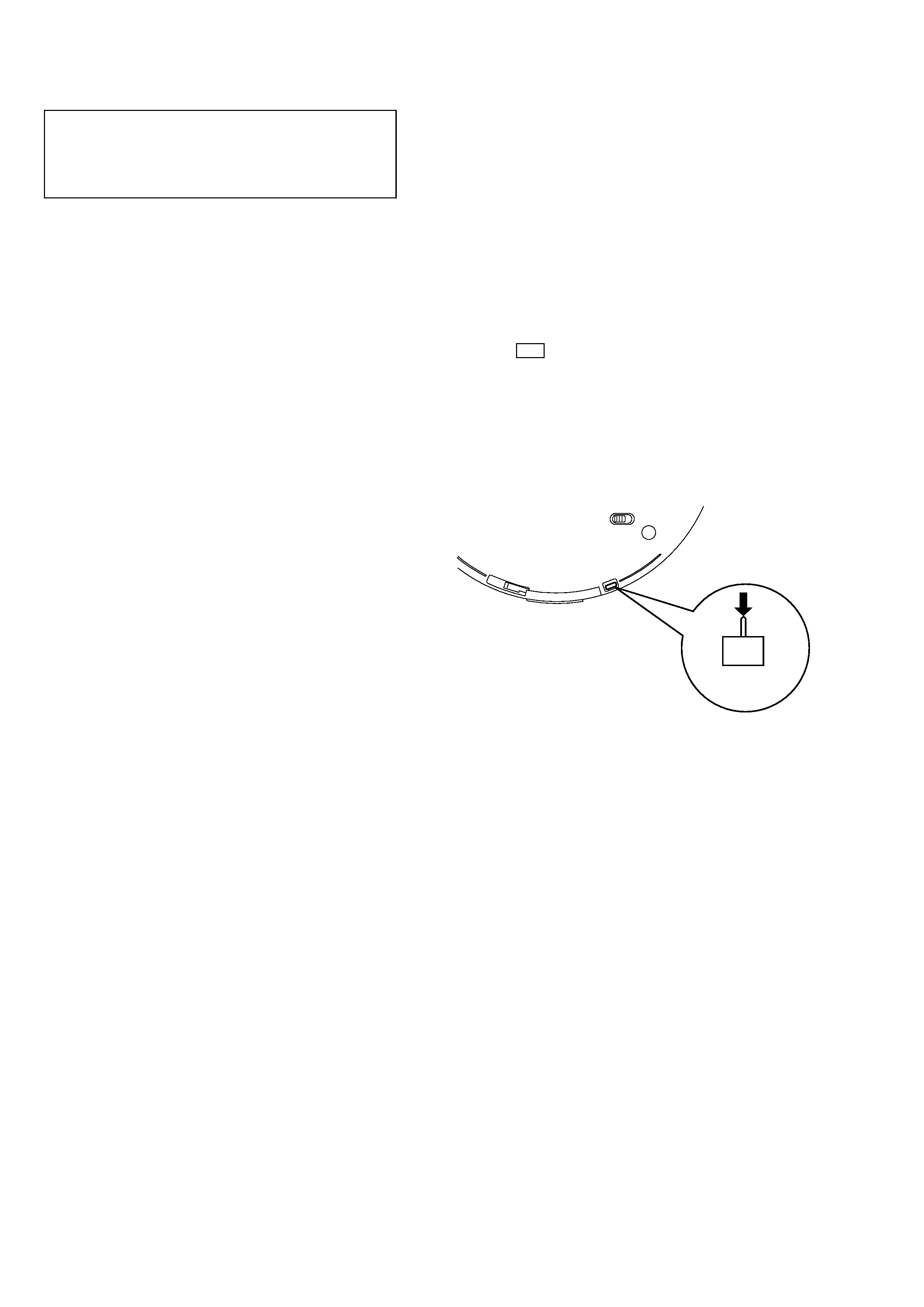
Laser Diode Checking Methods
During normal operation of the equipment, emission of the laser
diode is prohibited unless the upper lid is closed while turning ON
the S801. (push switch type)
The following two checking methods for the laser diode are
operable.
· Method:
Emission of the laser diode is visually checked.
1. Open the upper lid.
2. With a disc not set, turn on the S801 with a screwdriver having a
thin tip as shown in Fig.1.
Note: Do not push the detection lever strongly, or it may be bent
or damaged.
3. Press the u button.
4. Observing the objective lens, check that the laser diode emits
light.
When the laser diode does not emit light, automatic power
control circuit or optical pickup is faulty.
In this operation, the objective lens will move up and down 5
times along with inward motion for the focus search.
S801
Fig. 1

3
TABLE OF CONTENTS
1. GENERAL
Getting started ......................................................................... 4
Playing a VIDEO CD .............................................................. 4
Playing an audio CD................................................................ 5
2. DISASSEMBLY
2-1. Cabinet (Rear) Sub Assy, Cabinet (Upper), Main Board .... 6
2-2. MD Assy ............................................................................. 6
2-3. Motor Assy, Turntable (Spindle) (M901) ............................ 7
2-4. "Motor Assy, Sled (Sled) (M902)",
Optical Pick-up DAX-23E ................................................... 7
2-5. Switch Unit ......................................................................... 7
3. TEST MODE
3-1. Outline ................................................................................. 8
3-2. Pick-up Operational Checks ................................................ 8
3-3. Video Signal Verification .................................................... 8
4. ELECTRICAL ADJUSTMENT
4-1. Precautions for Check ......................................................... 9
4-2. Focus Bias Check ................................................................ 9
5. DIAGRAMS
5-1. IC Pin Descriptions ........................................................... 10
5-2. Block Diagram CD Section (1/2) .................................. 15
5-3. Block Diagram CD Section (2/2) .................................. 17
5-4. Block Diagram Video Section ....................................... 19
5-5. Block Diagram Power Supply Section .......................... 21
5-6. Printed Wiring Boards ....................................................... 25
5-7. Schematic Diagram Main Section (1/4) ........................ 29
5-8. Schematic Diagram Main Section (2/4) ........................ 31
5-9. Schematic Diagram Main Section (3/4) ........................ 33
5-10. Schematic Diagram Main Section (4/4) ........................ 35
6. EXPLODED VIEWS
6-1. Cabinet Section ................................................................. 39
6-2. CD Mechanism Deck Section ........................................... 40
7. ELECTRICAL PARTS LIST ......................................... 41
4
SECTION 1
GENERAL
This section is extracted
from instruction manual.
4
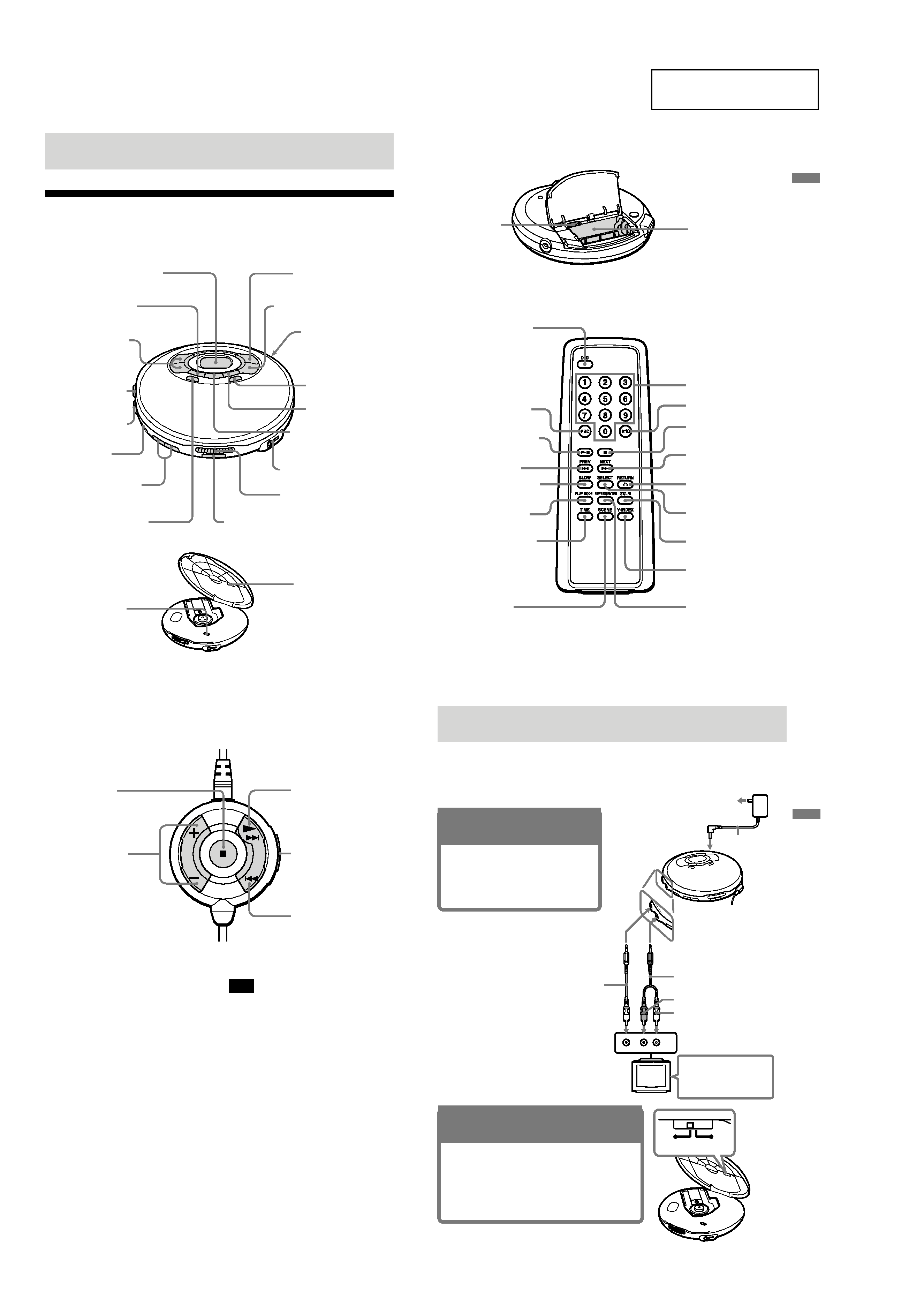
Getting started
Locating the Controls
For details, see pages in parentheses.
CD player (front)
CD player (inside)
qd SOUND button
(page 23)
1 Display (pages 9, 11, 21-24)
7 VOLUME +/ buttons
(page 10)
8 MENU button (page 15)
6 HOLD switch
(page 24)
2 PLAY MODE button
(pages 20-23)
5 AUDIO OUT jack
(pages 7, 17, 25)
4 VIDEO OUT jack
(pages 7, 17)
3
./>· PREV/
NEXT(AMS/search)
buttons (pages 9, 11,
16, 18, 21, 22)
ql NTSC/PAL switch
(pages 7)
qk G-PROTECTION
switch (pages 23)
qs RETURN O button
(page 15)
9
u (play/pause) button
(page 8-12, 14, 15, 23)
q;
x (stop) /CHG (charge)
button (pages 8-11, 27)
qa DC IN 4.5V (external
power input) jack
(pages 7, 10, 27)
qg i/REMOTE jack (page 10)
qh OPEN switch (pages 8, 10)
qf REPEAT/ENTER/
SELECT button
(page 11, 16, 20-23)
qj Remote sensor (pages 12)
5
CD player (rear)
Getting
started
Wireless remote control
wl Number buttons (pages
9, 11, 15, 18-20, 22)
ea
x (stop) button
(pages 8-11)
es NEXT > button
(pages 9, 11, 16, 18, 21, 22)
ef SELECT button
(pages 20)
This button does not
function on this model.
ej REPEAT/ENTER
button (pages 11, 16,
21-23)
e;
10 button (pages
15, 18, 19, 23)
ed RETURN O
button (page 15)
eg ST/L/R button
(page 14)
eh V-INDEX button
(page 18)
wf
u (play/pause) button
(pages 8-12, 14, 15, 23)
wk TIME button (page 19)
wh SLOW button (page 14)
wj PLAY MODE button
(pages 20 - 23)
wd PBC button (page 15)
wa Battery compartment
(pages 27)
ws OSD button (page12)
w; AVLS switch
(pages 24)
(Continued)
wg PREV . button
(pages 9, 11, 16, 18, 21, 22)
6
Remote control
Note
Use only the supplied remote control. You cannot
operate this VIDEO CD player with the remote
control supplied with other VIDEO CD players.
ek
x (stop) button
(pages 9-11)
r;
N(play) ·> (AMS/
search) button (pages 8-
11, 15, 16, 18, 22, 23)
ra HOLD switch
(page 24)
el VOL (volume) +/
button (page 10)
rs
. (AMS/search)
button (pages 9, 11, 16,
18, 22)
7
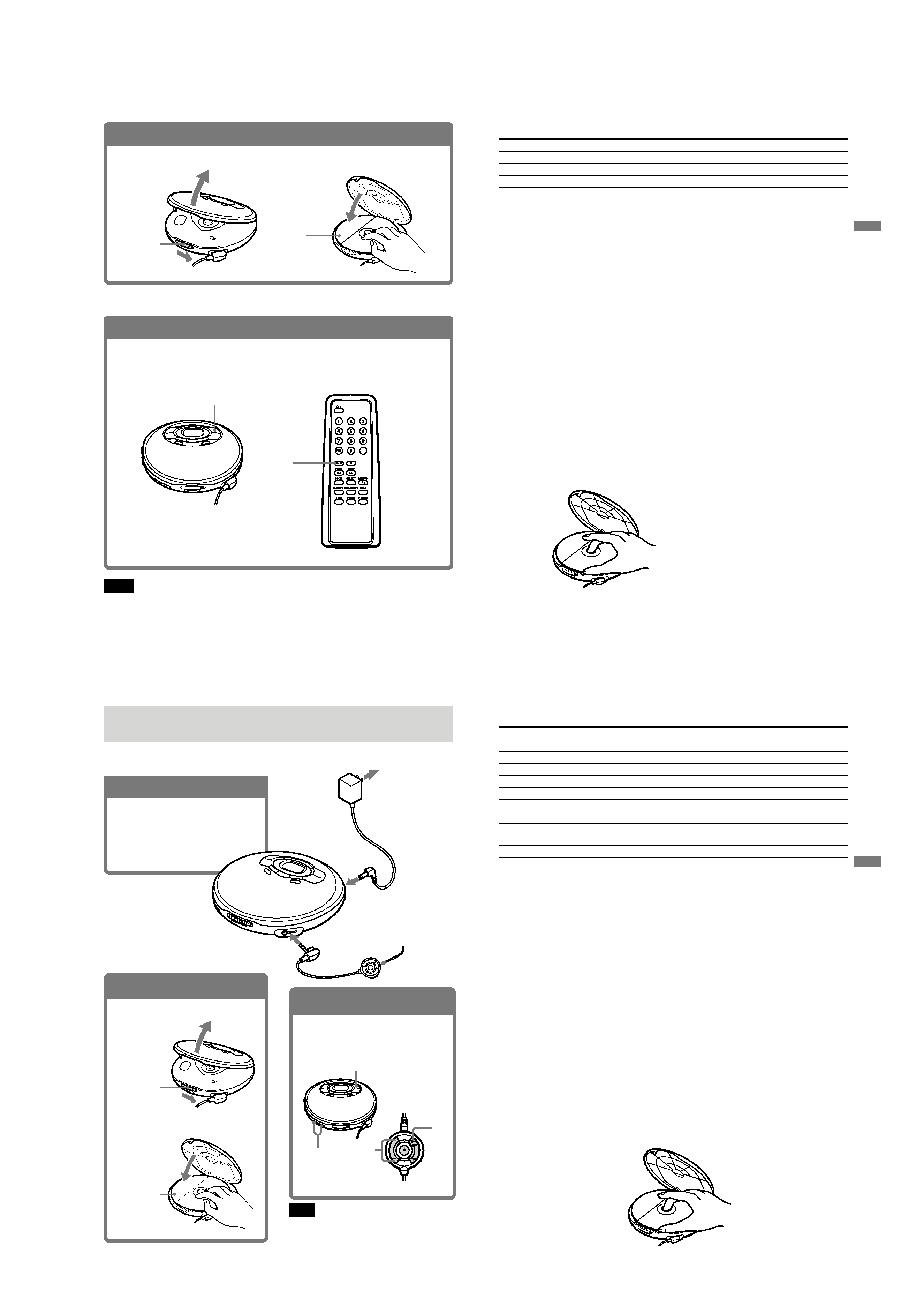
Playing a VIDEO CD
You can play back a VIDEO CD, using the supplied AC power adaptor. You can also use
rechargeable batteries and alkaline batteries. (See "Connecting a power source" on pages 27
29.)
To produce color pictures normally, you need to set the color system properly according to the
connected TV.
VIDEO
AUDIO
INPUT
RL
to an AC outlet
AC power
adaptor
to DC IN 4.5V
to AUDIO OUT
toVIDEO OUT
Audio cable
Yellow
Red
White
TV
PAL
NTSC
Video cable
Turn on the power and
set the input mode
selector to the proper
position.
Playing
a
VIDEO
CD
(Continued)
1. Connect your VIDEO CD
player.
1 Connect the AC power adaptor.
2 Connect the video and audio cables.
3 Turn on the power of the TV and set
the input mode selector to the proper
position.
2. Set the NTSC/PAL switch to the
color system of your TV.
1 Slide OPEN and raise the CD compartment lid.
2 Switch to "PAL" or "NTSC" using a pointed
material.
PAL system countries:
China, India, Indonesia, Singapore, Malaysia, etc.
NTSC system countries:
Japan, Korea, Taiwan, U.S.A., etc.
5
8
3. Insert a VIDEO CD.
1 Slide OPEN to open the lid.
2 Fit the VIDEO CD to the pivot and
close the lid.
OPEN switch
Label side
up
4. Play a VIDEO CD.
1 Press u on the main unit or the wireless remote control.
2 Adjust the volume on the equipment connected to this player. (You cannot adjust the
volume from this player except for the signals output from the i/REMOTE jack of the
player).
To stop playing, press x.
The player is also turned off.
u
u
Notes
The playback picture may be distorted when:
playing back a PAL system VIDEO CD on an NTSC system TV with the NTSC/PAL switch of this player
set to NTSC.
playing back an NTSC system VIDEO CD on a PAL system TV with the NTSC/PAL switch of this player
set to PAL.
9
Dothis
Press u.
Press x/CHG (x).
Press u (N).
Press > repeatedly until you find the scene or track.
Press . repeatedly unitl you find the scene or track.
Press the number button of the track (wireless remote
control only).
Press . or > and hold it down until m or M
appears on the TV screen.
To
Pause
Stop
Resume play after pause
Locate the next or succeeding tracks
Locate the current or preceding tracks
Locate a specific track directly
Locate a point in the track while monitoring
the picture*
* To return to normal playback, press u (N for the wireless remote control).
The above operations can also be done with the buttons on the supplied wired remote control or
wireless remote control.
About the display
· During play, the track number and the elapsed playing time of the current track appear.
· During pause, the elapsed playing time flashes.
If the volume level does not increase (when listening with the
headphones/earphone)
Is AVLS set to "LIMIT"? Set AVLS to "NORM." For details, see "To protect your hearing
(AVLS)" on page 24.
If a cable is connected to the AUDIO OUT jack, you cannot adjust the volume. In such a case,
disconnect the cable.
Removing the VIDEO CD
Remove the VIDEO CD as illustrated.
Playing
a
VIDEO
CD
10
Playing an audio CD
You can also use rechargeable batteries, alkaline batteries and a car battery. (See "Connecting a
power source" on pages 27 - 29.)
1. Connect your CD player.
1 Connect the AC power adaptor.
2 Connect the earphones with remote
control.
Connect the earphones firmly. A
loose connection may cause noise
during playback.
2. Insert an audio CD.
1 Slide OPEN to open the lid.
OPEN switch
Label side up
2 Fit the audio CD to the pivot and
close the lid.
3. Play an audio CD.
1 Press u on the main unit or press
N on the remote control.
2 Adjust the volume by pressing
VOLUME + or .
To stop playing, press x.
The player is also turned off.
u
VOLUME +/
VOL
N
Note
When playing back an audio CD using the AC
power adaptor, it takes a while until the sound is
heard.
Earphones with
remote control
(supplied)
to an AC outlet
AC power
adaptor
to DC IN
4.5V
to i/REMOTE
11
Playing
an
audio
CD
To
Pause
Stop
Resume play after pause
Find the beginning of the current track (AMS*)
Find the beginning of previous tracks (AMS)
Find the beginning of the next track (AMS)
Find the beginning of succeeding tracks (AMS)
Locate a specific track directly
Go forward quickly
Go backwards quickly
* Automatic Music Sensor
** These operations are possible during both play and pause.
The above operations can also be done with the buttons on the supplied wired remote control or
wireless remote control.
If you press REPEAT/ENTER to display "REPEAT", you can locate the tracks continuously in the following
order:
· When using >: next track t next track ...... last track t first track t second track ......
· When using .: previous track t previous track ...... first track t last track ......
About the display
· When you press u (N for the remote control), the total number of tracks in the audio CD
and total playing time appear for about two seconds.
· During play, the track number and the elapsed playing time of the current track appear.
· Between tracks, the time to the beginning of the next track appears with the "-" indication.
· During pause, the elapsed playing time flashes.
If the volume level does not increase
Is AVLS set to "LIMIT"? Set AVLS to "NORM." For details, see "To protect your hearing
(AVLS)" on page 24.
If a cable is connected to the AUDIO OUT jack, you cannot adjust the volume. In such a case,
disconnect the cable.
Removing the audio CD
Remove the audio CD as illustrated.
Press
u
x/CHG (x)
u (N)
. once**
. repeatedly**
> once**
> repeatedly**
Number buttons of the track (wireless remote
control only)**
Hold down >**
Hold down .**