1
Model Name Using Similar Mechanism
D-E01/EJ01
CD Mechanism Type
CDM-3022EBG
Optical Pick-up Name
DAX-22EG
SERVICE MANUAL
US Model
Canadian Model
AEP Model
UK Model
E Model
Australian Model
D-SJ01
PORTABLE CD PLAYER
MICROFILM
System
Compact disc digital audio system
Laser diode properties
Material: GaAlAs
Wavelength:
= 780 nm
Emission duration: Continuous
Laser output: Less than 44.6 µW (This output
is the value measured at a distance of 200 mm
from the objective lens surface on the optical
pick-up block with 7 mm aperture.)
D-A conversion
1-bit quartz time-axis control
Frequency response
20 - 20,000 Hz +1/2 dB
(measured by EIAJ CP-307)
Output (at 4.5 V input level)
Headphones (stereo minijack)
Approx. 5 mW + Approx. 5 mW
at 16 ohms
SPECIFICATIONS
Continued on next page
Power requirements
For the area code of the model you purchased,
check the upper left side of the bar code on the
package.
· Two Sony NC-WMAA rechargeable
batteries: 2.4 V DC
· Two LR6 (size AA) batteries: 3 V DC
· AC power adaptor (DC IN 4.5 V jack):
US, CND model: 120 V, 60 Hz
AEP, E13 model:
220 - 230 V, 50/60 Hz
UK model: 230 - 240V, 50 Hz
AUS model: 240 V, 50 Hz
E33 model: 100 - 240 V, 50/60 Hz
· Sony DCC-E245 car battery cord for use on
car battery: 4.5 V DC
Battery life * (approx. hours)
(When you use the CD player on a flat and stable
surface.)
Playing time varies depending on how the CD
player is used.
When using
G-PROTECTION function
off
on
Two NC-WMAA
12
11
(charged for
about 2.5 hours**)
NH-WM2AA
25
23
(charged for
about 4 hours**)
Two alkaline
40
37
batteries LR6
*
Measured value by the standard of EIAJ
(Electronic Industries Association of Japan).
**
Charging time varies depending on how the
rechargeable battery is used.
Ver 1.0 2000. 01
2
CAUTION
Use of controls or adjustments or performance of proce-
dures other than those specified herein may result in haz-
ardous radiation exposure.
Flexible Circuit Board Repairing
· Keep the temperature of the soldering iron around 270°C during
repairing.
· Do not touch the soldering iron on the same conductor of the
circuit board (within 3 times).
· Be careful not to apply force on the conductor when soldering
or unsoldering.
Notes on Chip Component Replacement
· Never reuse a disconnected chip component.
· Notice that the minus side of a tantalum capacitor may be
damaged by heat.
TABLE OF CONTENTS
1. SERVICE NOTE ................................................................ 3
2. GENERAL
Getting Started ......................................................................... 4
Playing a CD ........................................................................... 5
3. DISASSEMBLY
3-1. Hold Board .......................................................................... 6
3-2. Cabinet (M) ......................................................................... 6
3-3. Switch Unit ......................................................................... 7
3-4. CD Mechanism Deck .......................................................... 7
3-5. Main Board ......................................................................... 8
3-6. Control Board ...................................................................... 8
3-7. Optical Pick-up ................................................................... 9
4. TEST MODE
4-1. General Information .......................................................... 10
4-2. Test Mode .......................................................................... 10
5. ELECTRICAL ADJUSTMENTS
5-1. Focus Bias Check .............................................................. 11
6. DIAGRAMS
6-1. IC Pin Description ............................................................. 12
6-2. Block Diagram CD Section ........................................... 14
6-3. Block Diagram Power Supply Section .......................... 17
6-4. Printed Wiring Boards Main Section ............................ 19
6-5. Schematic Diagram Main Section (1/2) ........................ 23
6-6. Schematic Diagram Main Section (2/2) ........................ 25
6-7. IC Block Diagrams ............................................................ 27
7. EXPLODED VIEWS
7-1. Cabinet (Upper) Section .................................................... 30
7-2. Cabinet (Rear) Section ...................................................... 31
7-3. CD Mechanism Deck Section (CDM-3022EBG) ............. 32
8. ELECTRICAL PARTS LIST ......................................... 33
Operating temperature
5°C - 35°C (41°F - 95°C)
Dimensions (w/h/d) (excluding projecting parts
and controls)
Approx. 143.2
× 31 × 152.5 mm
(5 3/4
× 1 1/4 × 6 1/8 in.)
Mass (excluding accessories)
Approx. 320 g (11.3 oz.)
Supplied accessories
For the area code of the location in which you
purchased the CD player, check the upper left side
of the bar code on the package.
AC power adaptor AC-E455 (1)
Headphones/earphones with remote control
MDR-W014LP (1) (Except CND model)
MDR-G051LP (1) (CND model only)
Rechargeable batteries NC-WMAA (1)
Battery carrying case (1)
Carrying case (1)
Battery case (1)
AC plug adaptor (1) **
** Supplied with E33 model only
Design and specifications are subject to change without
notice.
SAFETY-RELATED COMPONENT WARNING!!
COMPONENTS IDENTIFIED BY MARK
0 OR DOTTED LINE
WITH MARK
0 ON THE SCHEMATIC DIAGRAMS AND IN
THE PARTS LIST ARE CRITICAL TO SAFE OPERATION.
REPLACE THESE COMPONENTS WITH SONY PARTS WHOSE
PART NUMBERS APPEAR AS SHOWN IN THIS MANUAL OR
IN SUPPLEMENTS PUBLISHED BY SONY.
ATTENTION AU COMPOSANT AYANT RAPPORT
À LA SÉCURITÉ!!
LES COMPOSANTS IDENTIFIÉS PAR UNE MARQUE
0 SUR LES
DIAGRAMMES SCHÉMATIQUES ET LA LISTE DES PIÈCES SONT
CRITIQUES POUR LA SÉCURITÉ DE FONCTIONNEMENT. NE
REMPLACER CES COMPOSANTS QUE PAR DES PIÈCES SONY
DONT LES NUMÉROS SONT DONNÉS DANS CE MANUEL OU
DANS LES SUPPLÉMENTS PUBLIÉS PAR SONY.
This Compact Disc player is
classified as a CLASS 1
LASER product.
The CLASS 1 LASER
PRODUCT table is located
on the bottom exterior.
· Abbreviation
CND : Canadian model
E13 : AC 220-230V area in E model
AUS : Australian model
E33 : AC 100-240V area in E model
3
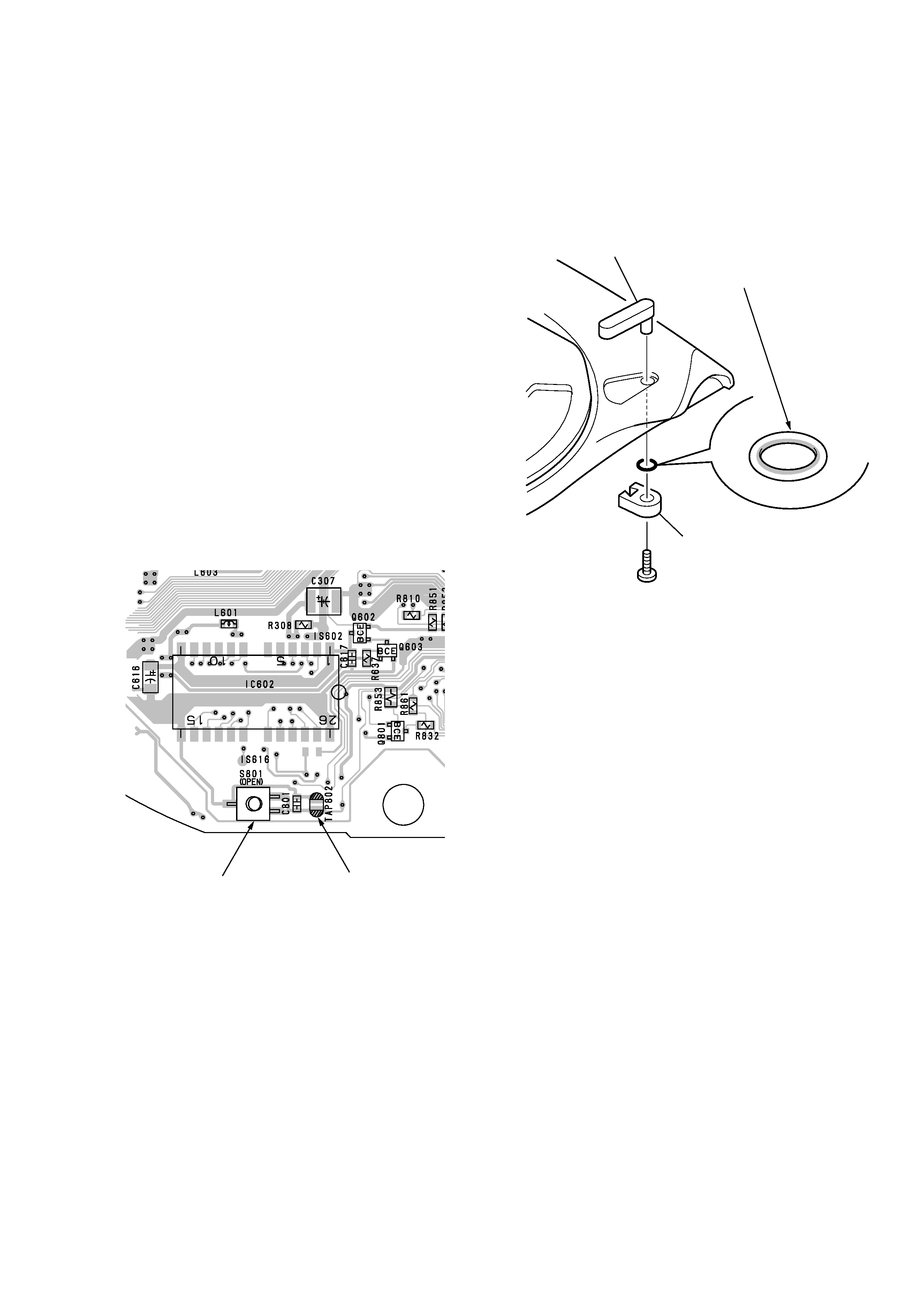
(OPEN)
S801
TAP802
main board (side A)
SECTION 1
SERVICE NOTE
· NOTES ON HANDLING THE OPTICAL PICK-UP BLOCK
OR BASE UNIT
The laser diode in the optical pick-up block may suffer electro-
static breakdown because of the potential difference generated by
the charged electrostatic load, etc. on clothing and the human body.
During repair, pay attention to electrostatic breakdown and also
use the procedure in the printed matter which is included in the
repair parts.
The flexible board is easily damaged and should be handled with
care.
· NOTES ON LASER DIODE EMISSION CHECK
The laser beam on this model is concentrated so as to be focused
on the disc reflective surface by the objective lens in the optical
pick-up block. Therefore, when checking the laser diode emis-
sion, observe from more than 30 cm away from the objective lens.
· To Check the Laser Diode and Focus Search Operation
Open the upper panel. Turn on the power without a disc while
the main board S801 (OPEN) is ON (or TAP802 is shorted). Then,
observe the objective lens and check that the following opera-
tions are performed.
1. Scatterd light of laser beams is seen.
2. Check for vertical movements (five) of the objective lens (with
movement of the PU on the inner circumference).
· Moisture Resistant Treatment
Be sure to perform the following work when the cabinet and ring
have been replaced in servicing :
Apply SONY grease SGL-505 (7-662-010-04) to the ring at the
points specified in the figure with an applicator or other means.
· Before Replacing the Optical Pick-Up Block
Please be sure to check throughly the parameters as par the "Opti-
cal Pick-Up Block Checking Procedures" (Part No.: 9-960-027-
11) issued separately before replacing the optical pick-up block.
Note and specifications required to check are given below.
· FOK output : IC601 eg pin
When checking FOK, remove the lead wire to disc motor.
When checking FOK value, remove the lead wire to disc
motor.
· RF signal P-to-P value : 0.35 - 0.65 Vp-p
· The repairing grating holder is impossible.
grease applying
points (ring)
lever (HOLD)
lever (SW)
4
SECTION 2
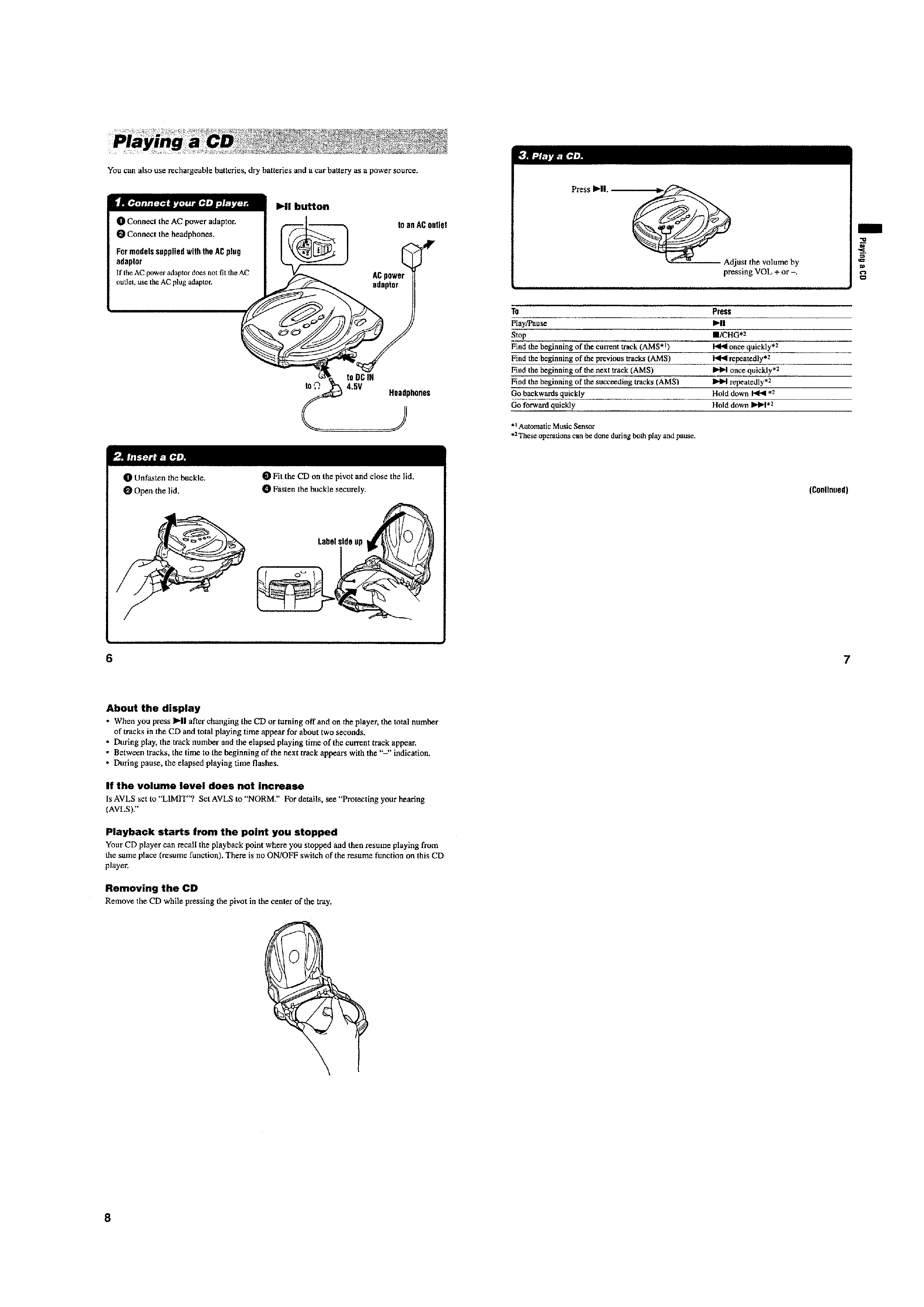
GENERAL
This section is extracted
from instruction manual.
5