SERVICE MANUAL
DIGITAL STILL CAMERA
SPECIFICATIONS
DSC-S70
Level 1
AEP Model
UK Model
System
Image device
1/1.8 type color CCD
Lens
3
× zoom lens
f = 7 21 mm
(34 102 mm when converted
into a 35 mm still camera)
F = 2.0 2.5
Exposure control
Automatic exposure
White balance
Automatic, Indoor, Outdoor,
Hold
Data system
Movie: MPEG1
Still: JPEG, GIF (in TEXT
mode), TIFF
Audio with still image:
MPEG1 (Monaural)
Recording medium
"Memory Stick"
Flash
Recommended recording
distance:
11 7/8 inches to 8 1/4 feet
(0.3 m to 2.5 m)
Output connector
A/V OUT (Monaural)
Minijack
Video: 1 Vp-p, 75
,
unbalanced, sync negative
Audio: 327 mV (at a 47 k
load)
Output impedance: 2.2 k
Digital I/O (USB)
Special minijack
External flash jack
Minijack
LCD screen
Used LCD panel
2 type TFT (Thin Film
Transistor active matrix) drive
Total number of dots
123 200 (560
× 220) dots
General
Used battery pack
NP-FM50
Power requirements
7.2 V
Power consumption
(during recording)
3.9 W
Operation temperature
32°F to 104°F
(0°C to 40°C)
Storage temperature
4°F to +140°F
(20°C to +60°C)
Maximum dimensions
4 5/8
× 2 7/8× 2 5/8 inches
(117
× 71× 64 mm) (w/h/d)
Mass
Approx. 15 oz (423 g)
(including battery pack NP-
FM50, "Memory Stick,"
shoulder strap and lens cap
etc.)
Built-in microphone
Electret condenser microphone
Built-in speaker
Dynamic speaker
AC-L10 AC power
adaptor
Power requirements
100 to 240 V AC, 50/60 Hz
Rated output voltage
DC 8.4 V, 1.5 A in operating
mode
Operation temperature
32°F to 104°F (0°C to 40°C)
Storage temperature
4°F to +140°F
(20°C to +60°C)
Maximum dimensions
5
× 1 9/16× 2 1/2 inches
(125
× 39× 62 mm) (w/h/d)
Mass
Approx. 10 oz (280 g)
NP-FM50 battery pack
Used battery
Lithium ion battery
Maximum voltage
DC 8.4 V
Nominal voltage
DC 7.2 V
Capacity
8.5 Wh (1 180 mAh)
Design and specifications are
subject to change without
notice.
Ver. 1.2 2001.07

2
1. Check the area of your repair for unsoldered or poorly-sol-
dered connections. Check the entire board surface for solder
splashes and bridges.
2. Check the interboard wiring to ensure that no wires are
"pinched" or contact high-wattage resistors.
3. Look for unauthorized replacement parts, particularly transis-
tors, that were installed during a previous repair. Point them
out to the customer and recommend their replacement.
SAFETY CHECK-OUT
After correcting the original service problem, perform the following
safety checks before releasing the set to the customer.
4. Look for parts which, though functioning, show obvious signs
of deterioration. Point them out to the customer and recom-
mend their replacement.
5. Check the B+ voltage to see it is at the values specified.
6. Flexible Circuit Board Repairing
·
Keep the temperature of the soldering iron around 270 °C
during repairing.
·
Do not touch the soldering iron on the same conductor of
the circuit board (within 3 times).
·
Be careful not to apply force on the conductor when sol-
dering or unsoldering.
SAFETY-RELATED COMPONENT WARNING!!
COMPONENTS IDENTIFIED BY MARK 0 OR DOTTED
LINE WITH MARK 0 ON THE SCHEMATIC DIAGRAMS
AND IN THE PARTS LIST ARE CRITICAL TO SAFE
OPERATION. REPLACE THESE COMPONENTS WITH
SONY PARTS WHOSE PART NUMBERS APPEAR AS
SHOWN IN THIS MANUAL OR IN SUPPLEMENTS PUB-
LISHED BY SONY.

3
TABLE OF CONTENTS
SERVICE NOTE
Self-diagnosis Display ................................................... 4
1.
MAIN PARTS
1.
Ornamental Parts .......................................................... 5
2.
DISASSEMBLY
2-1.
Front Cabinet Block Assembly ...................................... 6
2-2.
LCD Holder and Flash Unit ........................................... 7
2-3.
Battery Lid Assembly and Speaker ............................... 7
2-4.
Control Switch Block and Front Panel .......................... 8
2-5.
MS-54 Board and BT Holder Assembly ........................ 8
2-6.
Lens Block Assembly .................................................... 9
2-7.
SY-58 Board and DD-141 Board ................................... 9
2-8.
Control Switch Block, PD-128 Board and
Indicator Module ............................................................ 10
2-9.
SL-56 Board .................................................................. 10
3.
REPAIR PARTS LIST
3-1.
Exploded Views
3-1-1. Front Panel Section .................................................. 11
3-1-2. Front Cabinet Section .............................................. 12
3-1-3. Rear Cabinet Section ............................................... 13
3-1-4. Lens Block Assembly ............................................... 14
4.
GENERAL
Identifying the Parts ................................................................. 15
Preparing the Power Supply .................................................... 16
Setting the Date and Time ....................................................... 17
Inserting the "Memory Stick" ................................................... 18
Recording Still Images ............................................................ 18
Recording Moving Images ....................................................... 19
Playing Back Still Images ........................................................ 19
Playing Back Moving Images .................................................. 20
Viewing Images Using a Personal Computer ......................... 20
Image File Storage Destinations and Image Files .................. 21
Before Performing Advanced Operations ............................... 21
Various Recording ................................................................... 23
Various Playback ..................................................................... 25
Editing ...................................................................................... 26
Precautions .............................................................................. 27
On "Memory Sticks" ................................................................. 28
Using Your Camera Abroad ..................................................... 28
Troubleshooting ....................................................................... 28
Warning and Notice Messages ............................................... 29
Self-diagnosis Display ............................................................. 29
Display Window Indicators ...................................................... 30
LCD Screen Indicators ............................................................ 30
Section
Title
Page
4
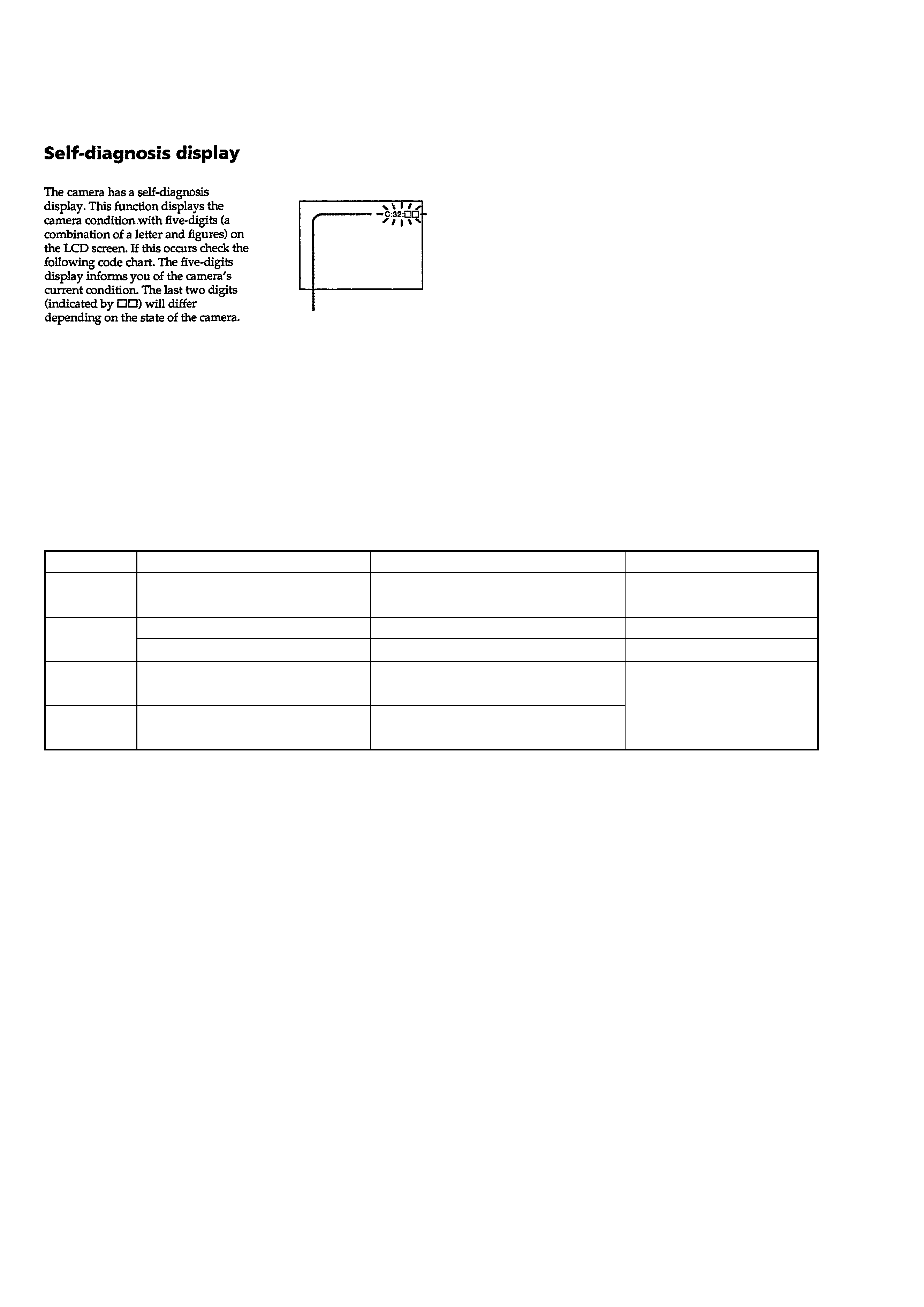
Self-diagnosis display
· C: ss
You can reverse the camera
malfunction yourself. (However,
contact your Sony dealer or local
authorized Sony service facility
when you cannot recover from the
camera malfunction.)
· E: ss
Contact your Sony dealer or local
authorized Sony service facility.
[Description on Self-diagnosis Display]
SERVICE NOTE
Display Code
C:32:ss
C:13:ss
E:61:ss
E:91:ss
Countermeasure
Turn the power off and on again.
Format the "Memory stick".
Insert a new "Memory Stick".
Checking of lens drive circuit.
Cause
Trouble with hardware.
Unformatted memory stick is inserted.
Memory stick is broken.
When failed in the focus and zoom
initialization.
Abnormality when flash is being
charged.
Checking of flash unit or replacement
of flash unit.
Caution Display During Error
SYSTEM ERROR
FORMAT ERROR
MEMORY STICK ERROR
--
*1
*2
Note: The error code is cleared if the battery is removed, except detective flash, unit.
*1: The error display is given in two ways.
*2: When the flash charging failed, Page : D, Address: 67. Data: 04 are written.
After repair, be sure to write Page: D, address: 67. Data: 00.
5
1. MAIN PARTS
Note:
· Items marked "*" are not stocked since they are seldom required for routine service.
Some delay should be anticipated when ordering these items.
· The parts numbers of such as a cabinet are also appeared in this section.
Refer to the parts number mentioned below the name of parts to order.
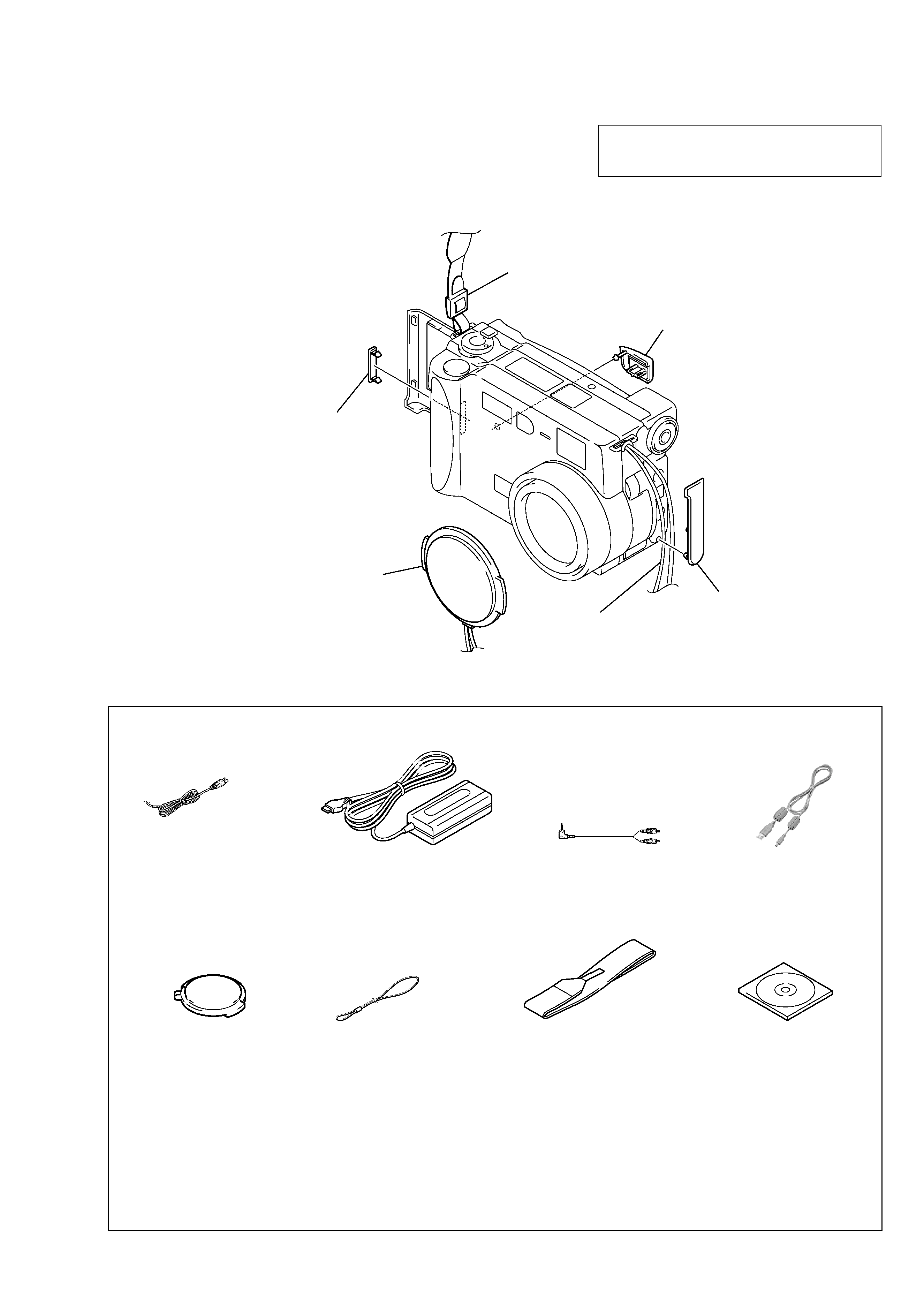
1.
ORNAMENTAL PARTS
The components identified by mark 0 or dotted
line with mark 0 are critical for safety.
Replace only with part number specified.
DSC-S70
DC cover
3-060-298-01
Shoulder belt
3-987-015-01
CPC lid
3-060-251-01
Lens cap assembly
X-3950-542-2
JK lid
3-060-301-01
Cap string
3-061-217-01
Checking supplied accessories.
Other accessories
3-060-522-11
MANUAL, INSTRUCTION (ENGLISH)
3-060-522-21
MANUAL, INSTRUCTION (FRENCH, GERMAN) (AEP)
3-060-522-31
MANUAL, INSTRUCTION (SPANISH, PORTUGUESE)
(AEP)
3-060-522-41
MANUAL, INSTRUCTION (ITALIAN, DUTCH) (AEP)
3-060-522-61
MANUAL, INSTRUCTION (RUSSIAN, SWEDISH) (AEP)
Power cord (1)
0 1-769-608-11 (AEP)
0 1-783-374-11 (UK)
AV connecting cable (1.5m) (1)
1-783-738-31
USB cable (1)
1-792-623-11
Lens cap assembly (1)
X-3950-542-2
Cap string (1)
3-061-217-01
AC adaptor (1)
0 1-475-599-11
Shoulder belt (S) (1)
3-987-015-01
Bundle soft (2000) (1)
3-060-716-01
Check that the following accessories are supplied with your digital still camera.