DSC-F55V
E Model
Australian Model
Hong Kong Model
Chinese Model
Tourist Model
Japanese Model
SERVICE MANUAL
DIGITAL STILL CAMERA
This service manual contains information
for japanese model as well.
Level 2
SPECIFICATIONS
On the SY-59 board
This service manual provides the information that is premised the circuit board
replacement service and not intended repair inside the SY-59 board.
Therefore, schematic diagram, printed wiring board and electrical parts list of
the SY-59 board are not shown.
The following pages are not shown.
Block diagram ............................... Page 3-9 to 3-16
Schematic diagram ....................... Page 4-9 to 4-34
Printed wiring board ..................... Page 4-35 to 4-36
Electrical parts list ........................ Page 6-8 to 6-14
The above-described information is shown in service manual Level 3.
System
Image device
1/1.8 type color CCD
Lens
f = 6.85 mm
(37 mm when converted into a
35 mm still camera)
F = 2.8
Exposure control
Automatic exposure
White balance
Automatic, Indoor, Outdoor,
Hold
Data system
Movie: MPEG1
Still: JPEG, GIF (in TEXT
mode), TIFF
Audio with still image:
MPEG1 (Monaural)
Recording medium
"Memory Stick"
Flash
Recommended recording
distance:
0.3m to 2.5m
Input and output
connector
A/V OUT (Monaural)
Minijack
Video: 1 Vp-p, 75
,
unbalanced, sync negative
Audio: 327 mV (at a 47 k
load)
Output impedance: 2.2 k
Digital I/O (USB)
Special minijack
LCD screen
Used LCD panel
2 type TFT (Thin Film
Transistor active matrix) drive
Total number of dots
123 200 (560
×220) dots
General
Used battery pack
NP-FS11
Power requirements
3.6 V
Power consumption
(during recording)
3.3 W
Operation temperature
0
°C to 40°C
Storage temperature
20
°C to +60°C
Maximum dimensions
Approx. 103
×79×48 mm
(w/h/d)
Mass
Approx. 300 g (including
battery pack NP-FS11,
"Memory Stick," lens cap,
etc.)
Built-in microphone
Electret condenser microphone
Built-in speaker
Dynamic speaker
AC-VF10 AC power
adaptor/charger
Power requirements
100 to 240 V AC, 50/60 Hz
Rated output voltage
DC OUT: DC 4.2 V, 1.8 A in
operating mode
Battery charge terminal:
DC 4.2 V, 1.5 A in charge
mode
Operation temperature
0
°C to 40°C
Storage temperature
20
°C to +60°C
Maximum dimensions
49
×39×85 mm (w/h/d)
Mass
Approx. 120 g
NP-FS11 battery pack
Used battery
Lithium ion battery
Maximum voltage
DC 4.2 V
Nominal voltage
DC 3.6 V
Capacity
4.1 Wh (1 140 mAh)
Accessories
A/V connecting cable (1)
NP-FS11 battery pack (1)
AC-VF10 AC power adaptor/
charger (1)
DK-115 DC connecting cable
(1)
Power cord (1)
USB cable (1)
Lens cap (1)
Lens cap strap (1)
Wrist strap (1)
"Memory Stick" (8 MB) (1)
CD-ROM (1)
Operating Instructions (1)
Design and specifications are
subject to change without
notice.
Ver 1.0 2000. 06

-- 2 --
SAFETY-RELATED COMPONENT WARNING!!
COMPONENTS IDENTIFIED BY MARK 0 OR DOTTED LINE WITH
MARK 0 ON THE SCHEMATIC DIAGRAMS AND IN THE PARTS
LIST ARE CRITICAL TO SAFE OPERATION. REPLACE THESE
COMPONENTS WITH SONY PARTS WHOSE PART NUMBERS
APPEAR AS SHOWN IN THIS MANUAL OR IN SUPPLEMENTS
PUBLISHED BY SONY.
1.
Check the area of your repair for unsoldered or poorly-soldered
connections. Check the entire board surface for solder splashes
and bridges.
2.
Check the interboard wiring to ensure that no wires are
"pinched" or contact high-wattage resistors.
3.
Look for unauthorized replacement parts, particularly
transistors, that were installed during a previous repair. Point
them out to the customer and recommend their replacement.
4.
Look for parts which, through functioning, show obvious signs
of deterioration. Point them out to the customer and
recommend their replacement.
5.
Check the B+ voltage to see it is at the values specified.
6.
Flexible Circuit Board Repairing
· Keep the temperature of the soldering iron around 270°C
during repairing.
· Do not touch the soldering iron on the same conductor of the
circuit board (within 3 times).
· Be careful not to apply force on the conductor when soldering
or unsoldering.
SAFETY CHECK-OUT
After correcting the original service problem, perform the following
safety checks before releasing the set to the customer.

-- 3 --
TABLE OF CONTENTS
2-6.
LCD, INVERTER TRANSFORMER UNIT ·················· 2-6
2-7.
LENS ASSEMBLY, FLASH UNIT,
MICROPHONE UNIT ···················································· 2-6
2-8.
CIRCUIT BOARDS LOCATION ··································· 2-7
2-9.
FLEXIBLE BOARDS LOCATION ································ 2-7
3.
BLOCK DIAGRAMS
3-1.
OVERALL BLOCK DIAGRAM (1/2) ··························· 3-1
3-2.
OVERALL BLOCK DIAGRAM (2/2) ··························· 3-3
3-3.
POWER BLOCK DIAGRAM (1/2) ································ 3-5
3-4.
POWER BLOCK DIAGRAM (2/2) ································ 3-7
4.
PRINTED WIRING BOARDS AND
SCHEMATIC DIAGRAMS
4-1.
FRAME SCHEMATIC DIAGRAM ································ 4-1
4-2.
PRINTED WIRING BOARDS AND SCHEMATIC
DIAGRAMS ···································································· 4-4
· CD-264 (CCD IMAGER)
PRINTED WIRING BOARD ························· 4-5
· CD-264 (CCD IMAGER)
SCHEMATIC DIAGRAM ······························ 4-7
· CONTROL SWITCH BLOCK (MS/HF)
SCHEMATIC DIAGRAM ···························· 4-37
· DD-143 (DC/DC CONVERTER)
SCHEMATIC DIAGRAM ···························· 4-39
· DD-143 (DC/DC CONVERTER)
PRINTED WIRING BOARD ······················· 4-41
4-3.
WAVEFORMS ······························································ 4-43
4-4.
MOUNTED PARTS LOCATION ································· 4-48
5.
ADJUSTMENTS
1.
Before starting adjustment ··············································· 5-1
1-1.
Adjusting items when replacing main parts and boards ·· 5-2
5-1.
ADJUSTMENTS ····························································· 5-3
1-1.
PREPARATIONS BEFORE ADJUSTMENT ················· 5-3
1-1-1. List of Service Tools ························································ 5-3
1-1-2. Preparations ····································································· 5-4
1-1-3. Discharging of the strobe power supply ·························· 5-4
1-1-4. Precaution ········································································ 5-6
1.
Setting the Switch ···························································· 5-6
2.
Order of Adjustments ······················································ 5-6
3.
Subjects ··········································································· 5-6
1-2.
INITIALIZATION OF B, D, E, F, 7 PAGE DATA ········· 5-7
1-2-1. INITIALIZATION OF D PAGE DATA ·························· 5-7
1.
Initializing the D Page Data ············································ 5-7
2.
Modification of D Page Data ··········································· 5-7
3.
D Page Table ···································································· 5-7
1-2-2. Initializing the B, E, F, 7 Page Data ································ 5-8
1.
Initializing the B, E, F, 7 Page Data ································ 5-8
2.
Modification of B, E, F, 7 Page Data ······························· 5-8
3.
F Page Table ···································································· 5-9
4.
7 Page Table ··································································· 5-10
5.
E Page Table ·································································· 5-11
6.
B Page Table ·································································· 5-11
1-3.
VIDEO SYSTEM ADJUSTMENTS ····························· 5-12
1.
Video Output Level Adjustment (SY-59 board) ············ 5-12
1-4.
CAMERA SYSTEM ADJUSTMENTS ························ 5-13
1.
HALL Adjustment ························································· 5-13
2.
Flange Back Adjustment (Using Minipattern Box) ······· 5-14
SERVICE NOTE ····································································· 5
1.
GENERAL
Getting started
Identifying the parts ······························································· 1-1
Preparing the power supply ··················································· 1-1
Setting the date and time ························································ 1-2
Inserting the "Memory Stick" ················································ 1-3
Basic operations
B Recording
Recording still images ··························································· 1-3
Recording moving images ····················································· 1-4
B Playback
Playing back still images ······················································· 1-4
Playing back moving images ················································· 1-4
Viewing images using a personal computer ·························· 1-5
Image file storage destinations and image files ····················· 1-6
Advanced operations
Before performing advanced operations
How to use the MODE selector ············································· 1-6
How to use the control button ················································ 1-6
How to change the menu settings ·········································· 1-7
Menu settings ········································································· 1-7
B Various recording
Rotating the LCD screen -- Face-to-Face recording ············ 1-8
Setting the image size (IMAGE SIZE) ·································· 1-8
Recording still images for e-mail (E-MAIL) ························· 1-8
Adding audio files to still images (VOICE) ·························· 1-9
Recording text documents (TEXT) ······································· 1-9
Recording uncompressed images (TIFF) ······························· 1-9
Recording images in macro ··················································· 1-9
Setting the distance to the subject ·········································· 1-9
Using the PROGRAM AE function ······································· 1-9
Adjusting the exposure (EXPOSURE) ·································· 1-9
Adjusting the white balance (WHITE BALANCE) ············ 1-10
Recording the date and time on the still image
(DATE/TIME) ······································································ 1-10
Enjoying picture effects (P.EFFECT) ·································· 1-10
B Various playback
Playing back six images at once (INDEX) ·························· 1-10
Enlarging a part of the still image (Zoom and trimming) ···· 1-10
Rotating a still image (ROTATE) ········································· 1-11
Playing back the images in order (SLIDE SHOW) ············· 1-11
Viewing images on a TV screen ·········································· 1-11
B Editing
Preventing accidental erasure (PROTECT) ························· 1-11
Deleting images (DELETE) ················································ 1-11
Changing the recorded still image size (RESIZE) ··············· 1-12
Copying images (COPY) ····················································· 1-12
Selecting still images to print (PRINT MARK) ·················· 1-12
Additional information
Precautions ··········································································· 1-12
On "Memory Sticks" ··························································· 1-13
Using your camera abroad ··················································· 1-13
Troubleshooting ··································································· 1-13
Warning and notice messages ·············································· 1-14
Self-diagnosis display ·························································· 1-14
LCD screen indicators ························································· 1-15
2.
DISASSEMBLY
2-1.
CABINET (FRONT) ASSEMBLY, CHECK COVER ···· 2-1
2-2.
DD-143 BOARD ····························································· 2-2
2-3.
CAMERA BLOCK ASSEMBLY ···································· 2-2
2-4.
SY-59 BOARD ································································ 2-3
2-5.
LCD PANEL BLOCK, SPEAKER (2.0CM),
CONTROL SWITCH BLOCK (MS)/(HF) ····················· 2-5
Schematic diagram and printed wiring board of the SY-
59 board are not shown.
Pages from 4-9 to 4-36 are not shown.
Founctional block diagrams are not shown.
Pages from 3-9 to 3-16 are not shown.

-- 4 --
3.
Flange Back Adjustment
(Using Flange Back Adjustment Chart) ························ 5-15
4.
Flange Back Check ························································ 5-15
5.
F No. Standard Data Input ············································· 5-15
6.
Mechanical Shutter Adjustment ···································· 5-16
7.
Picture Frame Setting ···················································· 5-17
8.
Light Level Adjustment and ND Shutter Check ············ 5-18
9.
Mixed Color Cancel Adjustment ··································· 5-18
10.
Auto White Balance Standard Data Input ····················· 5-19
11.
Auto White Balance Adjustment ··································· 5-19
12.
Color Reproduction Adjustment ···································· 5-20
13.
Color Reproduction Check ············································ 5-21
14.
White Balance Check ···················································· 5-22
15.
Strobe White Balance Adjustment ································· 5-23
16.
Strobe Light Level and White Balance Check ·············· 5-23
17.
CCD Black Defect Compensation ································· 5-24
18.
CCD White Defect Compensation ································ 5-24
1-5.
LCD SYSTEM ADJUSTMENT ··································· 5-25
1.
LCD Initial Data Input ·················································· 5-25
2.
VCO Adjustment (SY-59 board) ··································· 5-26
3.
D Range Adjustment (SY-59 board) ······························ 5-26
4.
Bright Adjustment (SY-59 board) ·································· 5-27
5.
Contrast Adjustment (SY-59 board) ······························ 5-27
6.
Color Adjustment (SY-59 board) ··································· 5-28
7.
V-COM Level Adjustment (SY-59 board) ····················· 5-28
8.
V-COM Adjustment (SY-59 board) ······························· 5-29
9.
White Balance Adjustment (SY-59 board) ···················· 5-29
1-6.
SYSTEM CONTROL SYSTEM ADJUSTMENT ········ 5-30
1.
Battery End Adjustment (SY-59 board) ························· 5-30
5-2.
SERVICE MODE ·························································· 5-31
2-1.
ADJUSTMENT REMOTE COMMANDER ················ 5-31
1.
Using the Adjustment Remote Commander ·················· 5-31
2.
Precautions Upon Using the Adjustment Remote
Commander ··································································· 5-31
2-2.
DATA PROCESS ··························································· 5-32
2-3.
SERVICE MODE ·························································· 5-33
1.
Setting the Test Mode ···················································· 5-33
2.
Bit Value Discrimination ··············································· 5-33
3.
Emergency Memory Address of Flash Unit ·················· 5-33
4.
Record of Use check ······················································ 5-34
5.
Self Diagnostics Log check ··········································· 5-34
6.
Switch check (1) ···························································· 5-35
7.
Switch check (2) ···························································· 5-35
8.
LED check ····································································· 5-35
9.
Position sensor check (SY-59 board SE401) ················· 5-36
6.
REPAIR PARTS LIST
6-1.
EXPLODED VIEWS ······················································ 6-1
6-1-1. OVERALL SECTION ····················································· 6-1
6-1-2. CABINET (FRONT) SECTION ····································· 6-2
6-1-3. CAMERA BLOCK SECTION ······································· 6-3
6-1-4. CABINET (REAR) SECTION ······································· 6-4
6-2.
ELECTRICAL PARTS LIST ·········································· 6-5
Electrical parts list of the SY-59 board is not shown.
pages 6-8 to 6-14 are not shown.
* Color reproduction frame is shown on page 105.
-- 5 --
SERVICE NOTE
· NOTE FOR REPAIR
[Discharging of the FLASH unit's charging capacitor]
The charging capacitor of the FLASH unit is charged up to the
maximum 300 V potential.
There is a danger of electric shock by this high voltage when the
capacitor is handled by hand. The electric shock is caused by the
charged voltage which is kept without discharging when the main
power of the DSC-F55V is simply turned off. Therefore, the
remaining voltage must be discharged as described below.
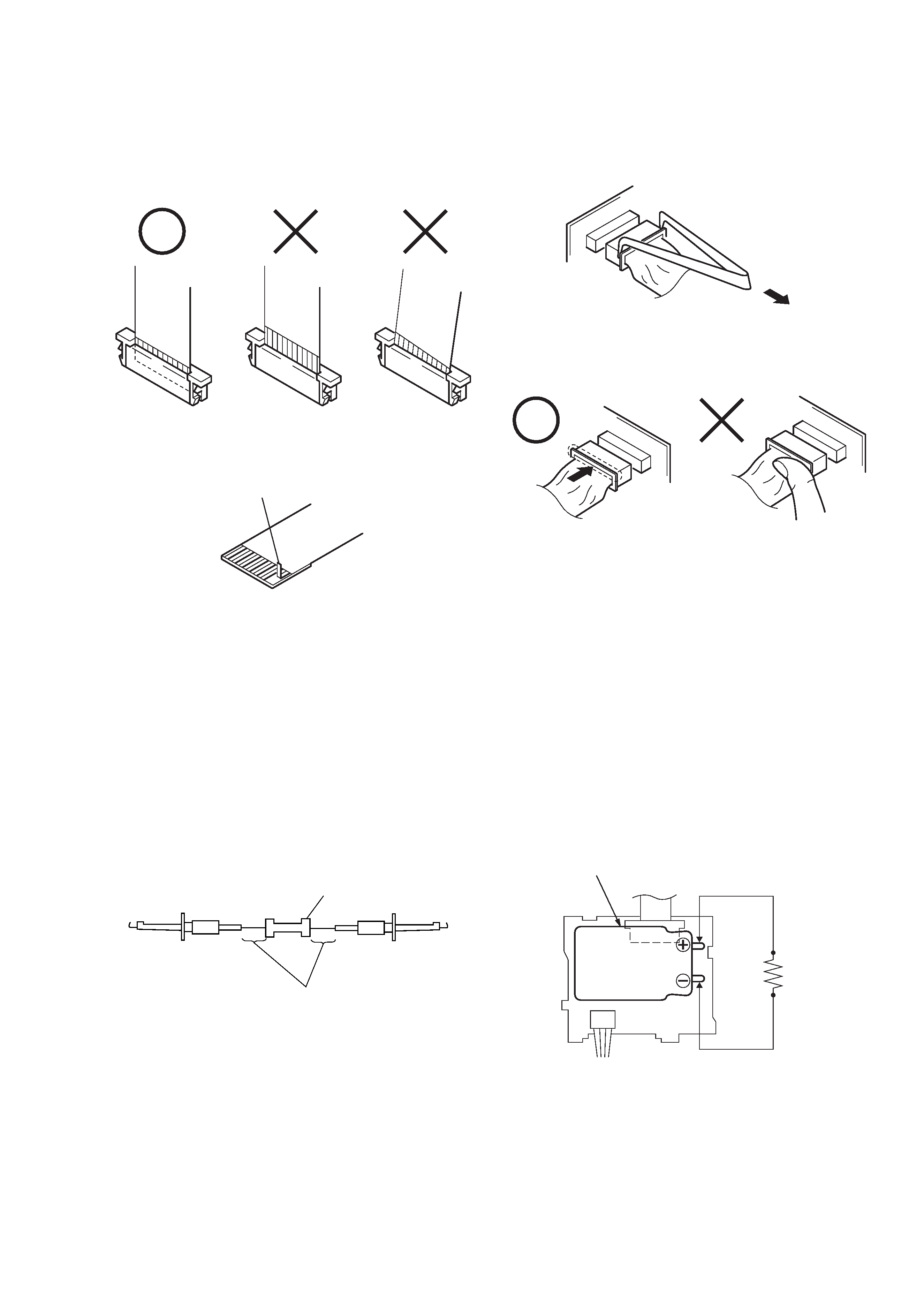
Preparing the Short Jig
To preparing the short jig. a small clip is attached to each end of a
resistor of 1 k
/1 W (1-215-869-11)
Wrap insulating tape fully around the leads of the resistor to prevent
electrical shock.
1 k
/1 W
Wrap insulating tape.
Make sure that the flat cable and flexible board are not cracked of
bent at the terminal.
Do not insert the cable insufficiently nor crookedly.
Cut and remove the part of gilt
which comes off at the point.
(Take care that there are
some pieces of gilt left inside)
When remove a connector, don't pull at wire of connector.
Be in danger of the snapping of a wire.
When installing a connector, don't press down at wire of connector.
Be in danger of the snapping of a wire.
Discharging the Capacitor
Short circuits between the positive and the negative terminals of
charged capacitor with the short jig about 10 seconds.
FLASH UNIT
Short jig
Capacitor