SERVICE MANUAL
SPECIFICATIONS
DSC-1024HD
Digital Scan Converter
US Model
Canadian Model
AEP Model
Chassis No. SCC-J91B-A
MICROFILM
Continued on next page
Signal input
VIDEO 1 IN
Composite video/reference input
BNC connector
× 2 (loop-through),
75 ohms (automatic termination)
NTSC3.58/PAL4.43, 1 Vp-p typical
Black burst signal for the gen-lock
function*
S video (Y/C)
4-pin mini DIN connector
× 2 (loop-
through), 75 ohms (automatic
termination)
Y: 1 Vp-p typical, sync negative
C: 0.286 Vp-p (NTSC)/0.3 Vp-p
(PAL) typical
VIDEO 2 IN
RGB/component/composite video
D-sub 15-pin, 3-row x 2 (loop-
through), 75 ohms/high
impedance
R/G/B: 0.714 Vp-p
H/V or composite sync: 1 to 5 Vp-p
Y/B-Y/R-Y: 0.7 Vp-p (NTSC/PAL,
sync on Y)
Composite video: 1 Vp-p
(NTSC3.58/PAL4.43)
VIDEO 3 IN
RGB/component
D-sub 15-pin, 3-row connector
× 2
(loop-through), 75 ohms/high
impedance
R/G/B: 0.714 Vp-p (sync on G
acceptable)
H/V or composite sync: 1 to 5 Vp-p
Y/B-Y/R-Y: 0.7 Vp-p typical
(NTSC/PAL, sync on Y)
AUDIO IN 1, 2, 3 (L/R) RCA pin jack, more than 10 kilohms
0 dBs (1 Vrms) max.
Video processing
Capture range
Horizontal rate: 15.6 to 70 kHz,
Vertical rate: 50 to 120 Hz
Preset signal
Input: 10 formats
Output: 7 formats
Gen-lock output: NTSC or PAL
(See page 49.)
Video memory
1,152
× 1,152 × 24 bits (RGB total)
Sampling rate
14.3 to 40 MHz offset phase max.
(equivalent to 80 MHz sampling)
Output pixel clock
14.3 to 50 MHz max.
General
Power requirements
100 to 120 V AC, 50/60 Hz, 0.4 A
200 to 240 V AC, 50 60 Hz, 0.25 A
Power consumption
30 W (max. in operation)
3 W (power off)
Operation temperature 0 to 35°C (32 95°F)
Dimensions
424
× 44 × 354 mm (w/h/d)
(16 3/4
× 1 3/4 × 14 inches)
excluding bracket and legs
Mass
Approx. 4.1 kg (9 lb 1 oz)
Supplied accessories
AC power cord (1)
Signal cable (1)
Screws for mounting bracket kit MB-
510 (4)
Optional accessories
Rack mount bracket MB-510
SMF-400: D-sub 15-pin (male) to 5 BNC cable
SMF-401: D-sub 15-pin (male) to D-sub 15-pin (male) cable
Remote commander RM-854, RM-1271, RM-PJ1292, RM-PJ350
* Note on the gen-lock function
The reference signal should comply with SMPTE 170M (NTSC)
or ITU-R624 (PAL).
DSC-1024HD
2
Signal output
VIDEO OUT
Composite video
BNC connector, 75 ohms typical
NTSC3.58/PAL4.43, 1 Vp-p typical
S video (Y/C)
4-pin mini DIN connector, 75 ohms
typical
Y: 1 Vp-p typical, sync negative
C: 0.286 Vp-p (NTSC)/0.3 Vp-p
(PAL) typical
RGB/component
D-sub 15-pin, 3-row connector, 75
ohms typical
R/G/B: 0.714 Vp-p with external
sync
H/V or composite sync: TTL sync
negative
Y/B-Y/R-Y: 0.7 Vp-p typical (sync
on Y)
AUDIO OUT (L/R)
RCA pin jack
Audio gain: ± 1.0 dB typical
Total harmonic distortion: less than
1 %, 1 Vrms
Signal standards
Scan lines
Line rate/field rate
525 lines total (interlaced)
15.73 kHz/59.94 Hz
625 lines total (interlaced)
15.63 kHz/50.00 Hz
1035 lines active (interlaced)
33.75 kHz/59.94 Hz
400 lines active (non-interlaced)
31.47 kHz/70.11 Hz
480 lines active (non-interlaced)
31.47 kHz/59.94 Hz
480 lines active (non-interlaced)
35.00 kHz/66.67 Hz
600 lines active (non-interlaced)
37.88 kHz/60.32 Hz
624 lines active (non-interlaced)
49.73 kHz/74.55 Hz
768 lines active (non-interlaced)
48.36 kHz/60.00 Hz
1024 lines active (non-interlaced)
63.95 kHz/59.94 Hz
1080 lines active (interlaced)
33.75 kHz/60 Hz, 59.94 Hz
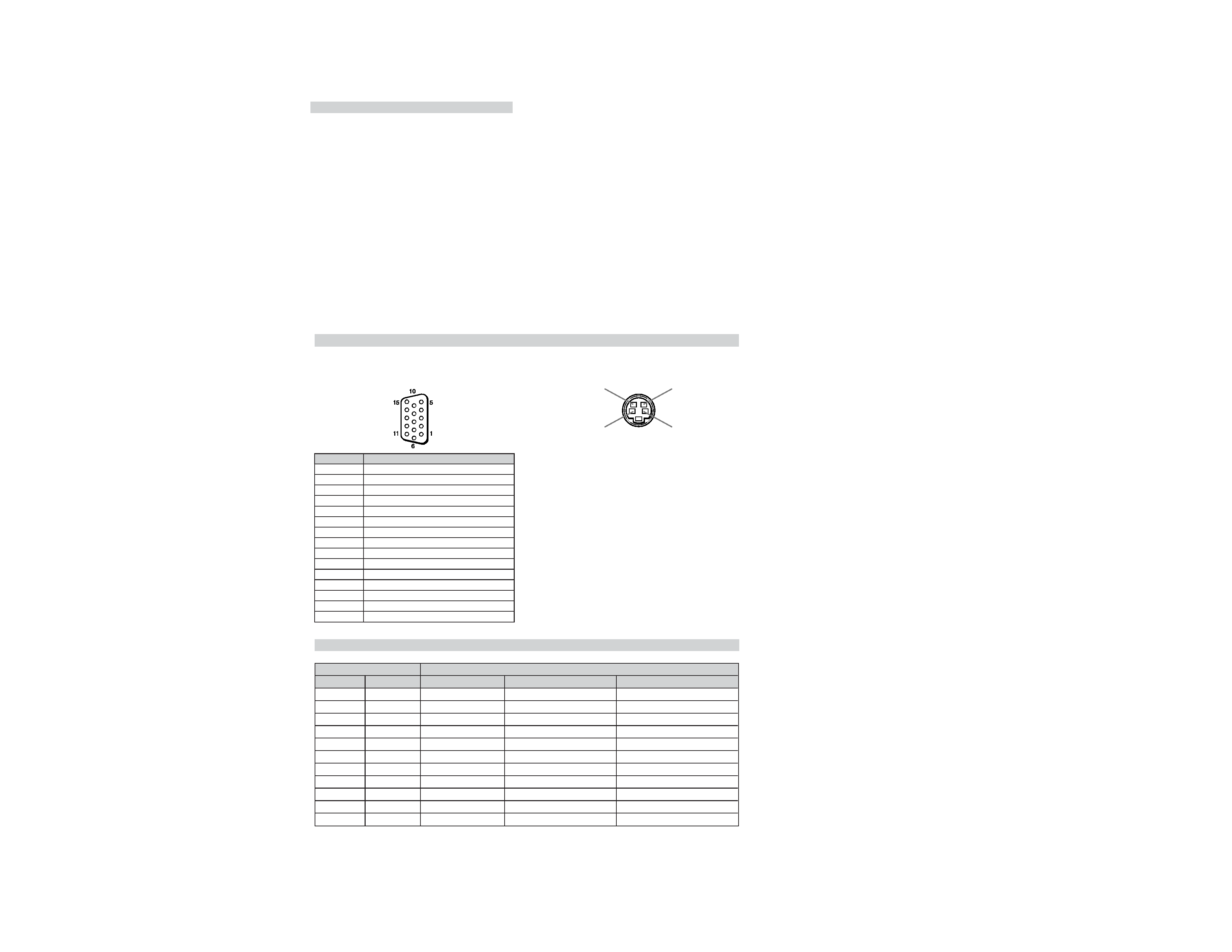
Signal assignment
VIDEO 2 IN connector (D-sub 15-pin, 3-row)
VIDEO 3 IN connector (D-sub 15-pin, 3-row)
VIDEO OUT connector (D-sub 15-pin, 3-row)
Y/C IN/OUT connector (4-pin mini DIN)
Pin No.
1
2
3
4
5
6
7
8
9
10
11
12
13
14
15
Signal
Red video or R-Y
Green video, Y or composite video*
Blue video or B-Y
Ground
Ground
Red ground
Green ground
Blue ground
Not used
Ground
Ground
Not used
H sync or composite sync
V sync
Not used
Preset signals
Chrominance
signal (C)
Ground
Luminance
signal (Y)
Ground
· H. SYNC and V. SYNC of all the output signals are negative.
VESA is a registered trademark of Video Electronics Standards Association.
VGA and SVGA are registered trademarks of International Business Machines Corporation.
Mac (Macintosh) is a registered trademark of Apple Computer, Inc.
Design and specifications are subject to change without notice.
Indicator
INPUT
NTSC
PAL
OTHERS
31.5k
31.5k
OTHERS
37k
OTHERS
48k
64k
--
OUTPUT
NTSC
PAL
--
--
31.5k
--
37k
--
48k
64k
1080i
Name
NTSC
PAL
HDTV 1920
× 1035 (Japan)
VGA Text
VGA 640
× 480
Mac 13" mode
VESA 800
× 600
Mac 16" mode
VESA 1024
× 768
VESA 1280
× 1024
HDTV 1920
× 1080
DSC-1024HD
3
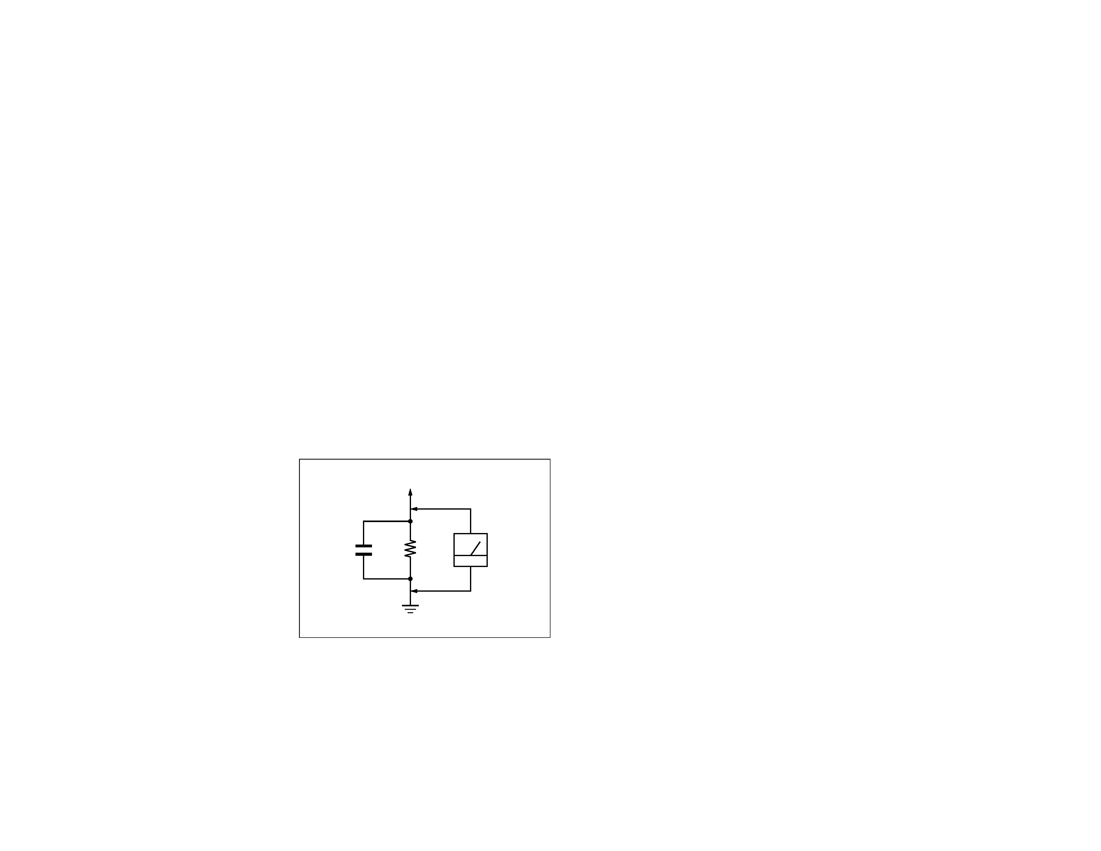
Fig. A. Using an AC voltmeter to check AC leakage.
SAFETY CHECK-OUT
1.5 k
0.15
µF
AC
Voltmeter
(0.75 V)
To Exposed Metal
Parts on Set
Earth Ground
After correcting the original service problem, perform the
following safety checks before releasing the set to the customer:
1. Check the area of your repair for unsoldered or poorly-sol-
dered connections. Check the entire board surface for solder
splashes and bridges.
2. Check the interboard wiring to ensure that no wires are
"pinched" or contact high-wattage resistors.
3. Check that all control knobs, shields, covers, ground straps,
and mounting hardware have been replaced. Be absolutely
certain that you have replaced all the insulators.
4. Look for unauthorized replacement parts, particularly tran-
sistors, that were installed during a previous repair. Point
them out to the customer and recommend their replacement.
5. Look for parts which, though functioning, show obvious
signs of deterioration. Point them out to the customer and
recommend their replacement.
6. Check the line cords for cracks and abrasion. Recommend
the replacement of any such line cord to the customer.
7. Check the B+ and HV to see if they are specified values.
Make sure your instruments are accurate; be suspicious of
your HV meter if sets always have low HV.
8. Check the antenna terminals, metal trim, "metallized" knobs,
screws, and all other exposed metal parts for AC Leakage.
Check leakage as described below.
LEAKAGE TEST
The AC leakage from any exposed metal part to earth ground
and from all exposed metal parts to any exposed metal part having
a return to chassis, must not exceed 0.5 mA (500 microamperes).
Leakage current can be measured by any one of three methods.
1. A commercial leakage tester, such as the Simpson 229 or
RCA WT-540A. Follow the manufacturers' instructions to
use these instruments.
2. A battery-operated AC milliammeter. The Data Precision
245 digital multimeter is suitable for this job.
3. Measuring the voltage drop across a resistor by means of a
VOM or battery-operated AC voltmeter. The "limit" indica-
tion is 0.75 V, so analog meters must have an accurate low-
voltage scale. The Simpson 250 and Sanwa SH-63Trd are
examples of a passive VOMs that are suitable. Nearly all
battery operated digital multimeters that have a 2 V AC
range are suitable. (See Fig. A)
WARNING!!
NEVER TURN ON THE POWER IN A CONDITION IN
WHICH THE DEGAUSS COIL HAS BEEN REMOVED.
SAFETY-RELATED COMPONENT WARNING!!
COMPONENTS IDENTIFIED BY SHADING AND MARK
¡
ON THE SCHEMATIC DIAGRAMS, EXPLODED VIEWS
AND IN THE PARTS LIST ARE CRITICAL FOR SAFE
OPERATION. REPLACE THESE COMPONENTS WITH
SONY PARTS WHOSE PART NUMBERS APPEAR AS
SHOWN IN THIS MANUAL OR IN SUPPLEMENTS
PUBLISHED BY SONY. CIRCUIT ADJUSTMENTS THAT
ARE CRITICAL FOR SAFE OPERATION ARE IDENTIFIED
IN THIS MANUAL. FOLLOW THESE PROCEDURES
WHENEVER CRITICAL COMPONENTS ARE REPLACED
OR IMPROPER OPERATION IS SUSPECTED.
AVERTISSEMENT!!
NE JAMAIS METTRE SOUS TENSION QUAND LA BOBINE
DE DEMAGNETISATION EST ENLEVÉE.
ATTENTION AUX COMPOSANTS RELATIFS À LA
SÉCURITÉ!!
LES COMPOSANTS IDENTIFIÉS PAR UNE TRAME ET
UNE MARQUE ¡ SONT CRITIQUES POUR LA SÉCURITÉ.
NE LES REMPLACER QUE PAR UNE PIÈCE PORTANT LE
NUMÉRO SPECIFIÉ. LES RÉGLAGES DE CIRCUIT DONT
L'IMPORTANCE EST CRITIQUE POUR LA SÉCURITÉ DU
FONCTIONNEMENT SONT IDENTIFIÉS DANS LE
PRÉSENT MANUEL. SUIVRE CES PROCÉDURES LORS
DE CHAQUE REMPLACEMENT DE COMPOSANTS CRI-
TIQUES, OU LORSQU'UN MAUVAIS FONCTIONNE-MENT
EST SUSPECTÉ.

DSC-1024HD
4
TABLE OF CONTENTS
Section
Title
Page
1. GENERAL ............................................................... 1-1
2. DISASSEMBLY ...................................................... 2-1
2-1.
Top Cover Removal ........................................... 2-1
2-2.
H1 and H2 Boards Removal .............................. 2-1
2-3.
K1 and K2 Boards Removal ............................. 2-1
3. SOFTWARE
(COLOR ADJUSTING, ETC.) ........................... 3-1
3-1.
Necessary Items .................................................. 3-1
3-2.
Purpose ............................................................... 3-1
3-3.
Setting ................................................................. 3-1
3-4.
Operation ............................................................ 3-1
3-5.
Color Adjustment Procedures ............................ 3-2
3-5-1. Preparations ...................................................... 3-2
3-5-2. Confirming Operations .................................... 3-2
3-5-3. Adjustment of Reference Frequency ............... 3-2
3-5-4. Adjustment of Subcarrier Frequency ............... 3-2
3-5-5. W/B Adjustment ............................................... 3-2
4. DIAGRAMS .............................................................. 4-1
4-1.
Block Diagrams .................................................. 4-1
4-2.
Frame Schematic Diagram ................................. 4-7
4-3.
Net Diagram (A Board) ...................................... 4-9
4-4.
Circuit Board Location ....................................... 4-11
4-5.
Schematic Diagrams and Printed
Wining Boards .................................................... 4-11
· Schematic Diagrams
(1)
A Board (COMB FILTER : 9/10) ...................... 4-19
(2)
A Board (I/O DECODER : 2/10) ....................... 4-27
(3)
A Board (LPF BLK : 8/10) ................................ 4-39
(4)
A Board (A/D : 3/10) ......................................... 4-31
(5)
A Board (R-MEM BLK : 4/10) .......................... 4-41
(6)
A Board (G-MEM BLK : 5/10) ......................... 4-43
(7)
A Board (B-MEM BLK : 6/10) .......................... 4-45
(8)
A Board (D/A ENCODER : 1/10) ..................... 4-23
(9)
A Board (CPU BLK : 7/10) ............................... 4-47
(10) A Board (GEN-LOCK : 10/10) .......................... 4-35
(11) G Board (POWER SUPPLY) ............................. 4-55
(12) H1 Board
(CONTROL SW, SIGNAL LAMP, SIRCS) ..... 4-51
(13) H2 Board
(CONTROL SW, SIGNAL LAMP) .................. 4-12
(14) K1 Board
(AUDIO IN/OUT, AUDIO INTER FACE) ...... 4-57
(15) K2 Board
(VIDEO IN/OUT, VIDEO INTER FACE) ....... 4-53
(16) J1 Board (CONTROL SW) ................................ 4-12
(17) J2 Board (CONTROL SW) ................................ 3-12
· Printed Wiring Boards
(1)
A Board (Main Board) ....................................... 4-15
(2)
G Board (POWER SUPPLY) ............................. 4-55
(3)
H1 Board
(CONTROL SW, SIGNAL LAMP, SIRCS) ..... 4-51
(4)
H2 Board
(CONTROL SW, SIGNAL LAMP) .................. 4-14
(5)
K1 Board
(AUDIO IN/OUT AUDIO INTER FACE) ....... 4-57
(6)
K2 Board
(VIDEO IN/OUT, VIDEO INTER FACE) ....... 4-53
(7)
J1 Board (CONTROL SW) ................................ 4-14
(8)
J2 Board (CONTROL SW) ................................ 4-14
4-6.
SEMICONDUCTORS ....................................... 4-58
5. EXPLODED VIEWS .............................................. 5-1
5-1.
Chassis ................................................................ 5-1
5-2.
Packing Materials ............................................... 5-2
6. ELECTRICAL PARTS LIST .............................. 6-1
Section
Title
Page
SECTION 1
GENERAL
The operating instructions mentioned here are partial abstracts
from the Operating Instruction Manual. The page numbers of
the Operating Instruction Manual remain as in the manual.
1-1
29
English
Generator lock (Gen-lock)
When you use this unit with your video editing system, the
output NTSC or PAL signal can be locked to a reference signal
(black burst video).
Aspect ratio display
The aspect ratio of the converted picture is displayed on the
screen as you zoom the picture or change the picture size.
Other features
· Three dimensional comb filter for NTSC Y/C separation
· Line correlation comb filter for PAL Y/C separation
· Up to
× 4 zooming
· Accepts infrared or wired Sony remote commanders using
SIRCS code
· On-screen display in five languages for user-friendly access
· Built-in test patterns for display alignment
· Three sets of video inputs with audio inputs: one composite
video or Y/C input, one composite video or RGB/
component input, and one RGB/component input
· Memory function for storage of up to five operation settings
· Automatic input signal detection with indication
· Self-adjusting for uniform output signal
· EIA rack mounting
· Selectable setup level (black reference level) for the output
NTSC signal
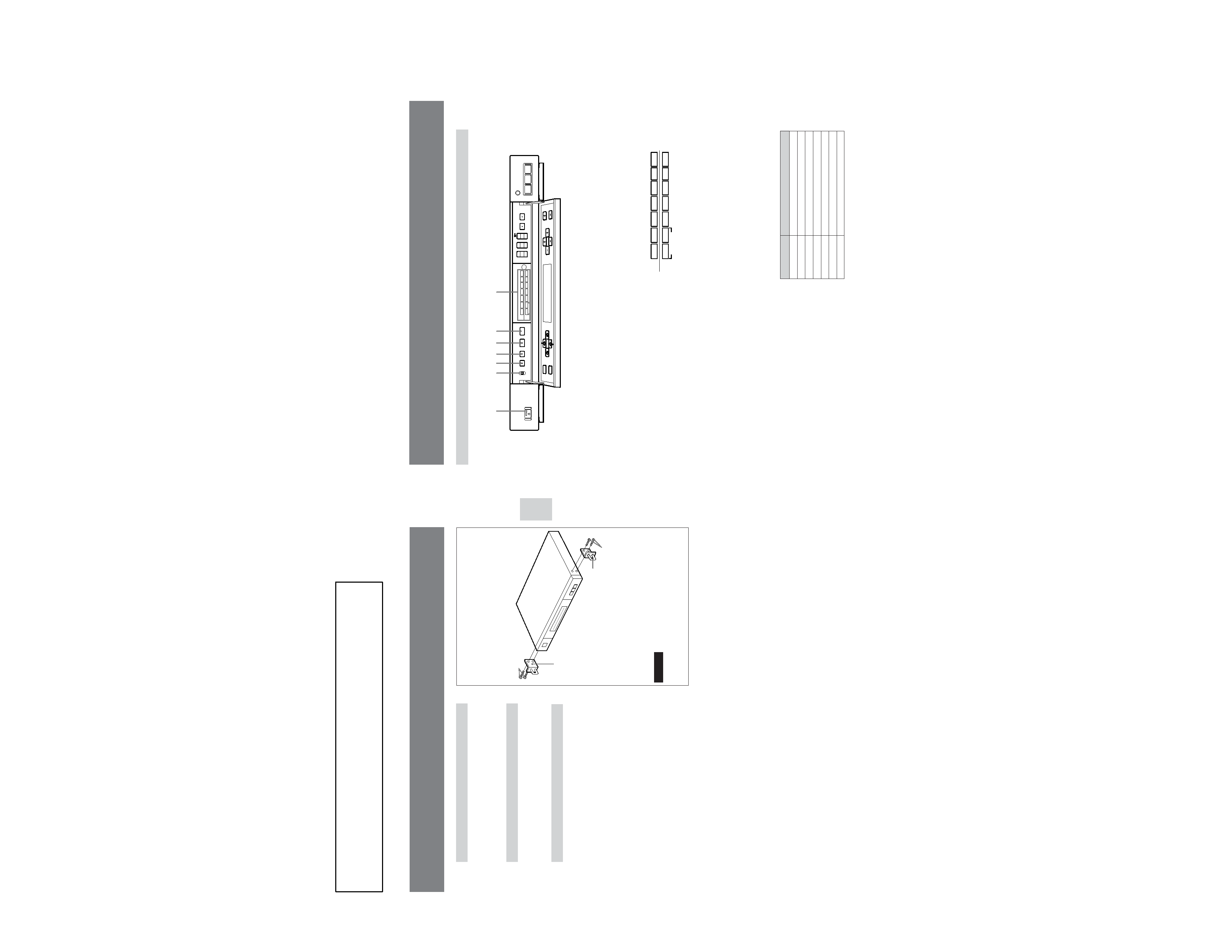
Rack mounting
You can mount the unit on a 19-inch EIA standard rack
using the optional MB-510 mounting bracket kit.
1 Attach the handle brackets with the four screws
included with this unit.
2 Remove the four legs from the bottom of the unit.
3 Mount the unit into a 19-inch standard rack.
Caution
Do not hold the handle brackets to carry the unit. If you do,
the unit may separate from the handle brackets.
Handle bracket
Handle bracket
Screws
Screws
30
Front panel
6 OUTPUT FORMAT button
Press this button to select the desired output signal format.
The selected output signal indicator lights.
7 SIGNAL FORMAT indicators
IN indicators (upper)
Shows the input signal format that the unit automatically
detected.
31.5k, 37k, 48k and 64k indicate the horizontal scanning
frequencies. If the horizontal scanning frequency of the
input signal detected is one of these values ±1 kHz, the
corresponding indicator lights. If another value is
detected, the OTHERS indicator lights.
OUT indicators (lower)
Shows the output signal format selected by the OUTPUT
FORMAT button. The output signal format shown by each
indicator is as follows:
For specifications of each format, see "Preset signals" on
page 49.
GEN-LOCK indicator
When the output signal format is PAL or NTSC and GEN
LOCK is set to ON on the menu screen, the GEN-LOCK
indicator lights or flashes.
Location and function of parts and controls
1 ON/OFF (power) switch and indicator
Press to turn the unit on and off.
The indicator on the switch lights when the unit is turned
on.
2 COMMAND MODE selector
When using the remote commander supplied with the
Sony monitor or TV, set it to TV.
When using the remote commander supplied with the
Sony projector, set it to PJ.
When not using the remote commander, set to OFF.
3 DISPLAY ON/OFF button and indicator
Press this button to turn on the indicator (DISPLAY ON) to
display the current operating mode on the screen.
Press it again to turn off the indicator to eliminate the
display (DISPLAY OFF).
Note
The main menu appears by pressing the MENU button,
even if the DISPLAY OFF mode is selected.
4 TEST PATTERN button and indicator
Press this button to turn on the indicator to display the test
pattern on the screen.
To turn off the test pattern, press the TEST PATTERN
button repeatedly until no test pattern is displayed, or
press the ON/OFF, INPUT SELECT or OUTPUT
FORMAT button.
5 LINE DOUBLER button and indicator
When the input signal format is NTSC or PAL, press this
button to turn on the indicator and activate the line doubler
function. Press it again to turn off the indicator and cancel
the line doubler function.
Format name
NTSC
PAL
VGA 640
× 480
VESA 800
× 600
VESA 1024
× 768
VESA 1280
× 1024
HDTV 1920
× 1080
OUT indicator
NTSC
PAL
31.5k
37k
48k
64k
1080i
NTSC
NTSC
IN
OUT
PAL
PAL
31.5k
31.5k
37k
37k
48k
48k
64k OTHERS
64k
1080i
SIGNAL FORMAT
CHROMA
CONTRAST
APERTURE
OUTPUT
FORMAT
LINE
DOUBLER
OVER FLOW
STILL
OPEN
SCAN CONVERTER DSC-1024HD
INPUT SELECT
PHASE
12
3
TEST
PATTERN
DISPLAY
ON/OFF
TV
PJ
OFF
COMMAND
MODE
ON/OFF
MENU
ENTER
CENT
ZOOM
SIZE
V
V
H
H
234 5 6
7
S
1
GEN-LOCK
NTSC
NTSC
IN
OUT
PAL
PAL
31.5k
31.5k
37k
37k
48k
48k
64k OTHERS
64k
SIGNAL FORMAT
GEN-LOCK
1080i