DRN-XM01C/XM01R/XM01H/
XM01CK/XM01HK
US Model
SERVICE MANUAL
DIGITAL AUDIO RECEIVER
SPECIFICATIONS
Ver 1.1 2001. 12
Time display
12-hour system
Auto power down function
OFF/60 min/120 min/180 min
Output
LINE OUT jack (ø 3.5 mm stereo minijack)
Power requirements
6 V DC, DC IN 6V jack
Dimensions
Incl. projecting parts and controls:
Main unit:
Approx. 105
× 40 × 120 mm (w/h/d)
(Approx. 4 1/4 × 1 5/8 × 4 3/4 inches)
When the main unit is installed in the car cradle with the car stand:
Approx. 105
× 68 × 128 mm (w/h/d)
(Approx. 4 1/4 × 2 3/4 × 5 1/8 inches)
When the main unit is installed in the home cradle with the home
stand:
Approx. 105
× 55 × 128 mm (w/h/d)
(Approx. 4 1/
4 × 2
1/
4 × 5
1/
8 inches)
Not incl. projecting parts and controls:
Main unit:
Approx. 102
× 38 × 120 mm (w/h/d)
(Approx. 4 1/8 × 1 1/2 × 4 3/4 inches)
When the main unit is installed in the car cradle with the car stand:
Approx. 102
× 66 × 128 mm (w/h/d)
(Approx. 4 1/
8 × 2
5/
8 × 5
1/
8 inches)
When the main unit is installed in the home cradle with the home
stand:
Approx. 102
× 53 × 128 mm (w/h/d)
(Approx. 4 1/
8 × 2
1/
8 × 5
1/
8 inches)
Mass
Main unit:
Approx. 220 g (7.8 oz)
When the main unit is installed in the car cradle with the car stand:
Approx. 380 g (13.4 oz)
When the main unit is installed in the home cradle with the home
stand:
Approx. 300 g (10.6 oz)
Remote commander
Power requirements
3V DC, one CR2025 lithium battery
Dimensions
Approx. 52
× 89 × 12 mm (w/h/d)
(Approx. 2 1/
8 × 3
5/
8 ×
1/
2 inches)
incl. projecting parts and controls
Mass
Approx. 30 g (1.1 oz) incl. lithium battery
Design and specifications are subject to change without notice.
Main unit
Accessories supplied
XM antenna (1)
Remote commander (1)
For DRN-XM01C/XM01CK/XM01R:
Car cradle (1)
Car stand (1)
Screw (5)
Cover (1)
Water proof cushion (1)
Cable guide (3)
Cord clamp (4)
Cushion with the double-sided adhesive tape (1)
Seal (1)
For DRN-XM01C/XM01CK only:
Car battery cord (1)
Car connecting pack (1)
For DRN-XM01R only:
RF modulator (1)
For DRN-XM01H/XM01HK:
Home cradle (1)
Home stand (1)
Audio cord (1)
AC power adaptor (1)
Sony Corporation
Personal Audio Company
Published by Sony Engineering Corporation
9-873-268-02
2001L1600-1
© 2001.12

2
SAFETY-RELATED COMPONENT WARNING!!
COMPONENTS IDENTIFIED BY MARK 0 OR DOTTED LINE WITH
MARK 0 ON THE SCHEMATIC DIAGRAMS AND IN THE PARTS
LIST ARE CRITICAL TO SAFE OPERATION. REPLACE THESE
COMPONENTS WITH SONY PARTS WHOSE PART NUMBERS
APPEAR AS SHOWN IN THIS MANUAL OR IN SUPPLEMENTS
PUBLISHED BY SONY.
Notes on chip component replacement
· Never reuse a disconnected chip component.
· Notice that the minus side of a tantalum capacitor may be
damaged by heat.
Flexible Circuit Board Repairing
· Keep the temperature of soldering iron around 270°C
during repairing.
· Do not touch the soldering iron on the same conductor of the
circuit Board (within 3 times).
· Be careful not to apply force on the conductor when soldering
or unsoldering.
DRN-XM01C/XM01R/XM01H/
XM01CK/XM01HK
1. SERVICING NOTES ················································· 3
2. GENERAL ·································································· 5
3. DISASSEMBLY ························································· 7
3-1.
Front Panel Assy ·························································· 7
3-2.
LCD Board ··································································· 7
3-3.
Lower Cabinet Assembly,
Upper Cabinet Assembly ············································· 8
3-4.
BB Board, DC FAN ····················································· 8
3-5.
CPU Board, USB Board ··············································· 9
4. TEST MODE ···························································· 10
4-1.
Test Mode ··································································· 10
4-2.
Diagnostic Mode ························································ 11
4-3.
System Error List ······················································· 11
5. SERVICE TOOL
5-1.
Installing USB Driver ················································· 12
5-2.
Installing DRN-XM01 Service Tool ·························· 19
5.3.
How To Use DRN-XM01 Service Tool ····················· 22
6. DIAGRAMS ······························································ 26
6-1.
Block Diagram Tuner Section ······························ 27
Control Section ···················································· 28
6-2.
Printed Wiring Boards CPU Board ······················ 29
6-3.
Schematic Diagram CPU Board (1/2) ·················· 30
6-4.
Schematic Diagram CPU Board (2/2) ·················· 31
6-5.
Printed Wiring Boards BB Board ························· 32
6-6.
Schematic Diagram BB Board (1/3) ···················· 33
6-7.
Schematic Diagram BB Board (2/3) ···················· 34
6-8.
Schematic Diagram BB Board (3/3) ···················· 35
6-9.
Printed Wiring Boards Panel Section ··················· 36
6-10. Schematic Diagram Panel Section ······················· 37
6-11. IC Block Diagrams ····················································· 38
6-12. IC Pin Function Description ······································ 40
7. EXPLODED VIEWS
7-1.
Front Panel Assembly,
Lower Panel Assembly ··············································· 42
7-2.
Upper Cabinet Assembly ··········································· 43
8. ELECTRICAL PARTS LIST ·································· 44
TABLE OF CONTENTS

3
DRN-XM01C/XM01R/XM01H/
XM01CK/XM01HK
SECTION 1
SERVICING NOTES
Ver 1.1 2001.12
What to do when memory or the BB board or the unit is replaced?
The DRN-XM01 Service Tool is simply referred to as "the dedicated software" in this document.
· When IC504 (flash memory) is replaced
Connect the DRN-XM01 to a PC with the USB cable and enter the serial number in the dedicated software. Then
write the newest program in the flash memory.
(Contents of the user setup are automatically cleared.)
· When IC509 (EEPROM) is replaced
Connect the DRN-XM01 to a PC with the USB cable and enter the serial number in the dedicated software. Then
write the newest program in the flash memory.
(Contents of the user setup are automatically cleared.)
· When failed in writing the flash memory
Connect again the DRN-XM01 to the PC with the USB cable and enter the serial number in the dedicated software.
Then write the newest program in the flash memory.
(Contents of the user setup are automatically cleared.)
· When IC102 (STA450) is replaced
Replace IC103 (ST19AF08) at the same time.
Then perform the CAP-binding (see Note 1) using the dedicated equipment (see Note 2).
Write the radio ID that is displayed on the binding computer, into the label.
Connect again the DRN-XM01 to the PC with the USB cable and enter the serial number in the dedicated software.
Then write the newest program in the flash memory.
(Contents of the user setup are automatically cleared.)
Turn on the power of the DRN-XM01. Confirm that the radio ID that is displayed on the CH0 matches the number
on the label. Then attach the label to the DRN-XM01.
After that, update the contract with the XM Radio Inc. Ltd., accordingly.
· When IC103 (ST19AF08) is replaced
Perform the CAP-binding using the dedicated equipment.
Confirm that the radio ID that is displayed on the binding computer matches the indication on the label of the DRN-XM01.
Connect the DRN-XM01 to a PC with the USB cable and enter the newest program in the flash memory using the
dedicated software.
(Contents of the user setup are automatically cleared.)
Turn on the power of the DRN-XM01. Confirm that the radio ID that is displayed on the CH0 matches the number
on the label.
After that, update the contract with the XM Radio Inc. Ltd., accordingly.
· When the BB board is replaced
Perform the CAP-binding using the dedicated equipment.
Write the radio ID that is displayed on the binding computer, into the label.
Connect the DRN-XM01 to a PC with the USB cable and write the newest program in the flash memory using the
dedicated software.
(Contents of the user setup are automatically cleared.)
Turn on the power of the DRN-XM01. Confirm that the radio ID that is displayed on the CH0 matches the number
on the label.
After that, update the contract with the XM Radio Inc. Ltd., accordingly.
· When the CPU board is replaced
Connect the DRN-XM01 to a PC with the USB cable and write the newest program in the flash memory using the
dedicated software.
(Contents of the user setup are automatically cleared.)
· When the DRN-XM01 is replaced
Perform the "activate" work (see Note 3). Update the contract with the XM Radio Inc. Ltd., accordingly.
Note 1 : CAP : IC103 ST19AF08 (Conditional Access Processor)
Note 2 : Dedicated equipment : It means the dedicated pin-jig that connects the BB board to a binding PC that is
used for the CAP-binding i.e., the procedure of writing the radio ID (XM Radio Hardware ID) to support
the pay services.
Note 3 : "activate" work: The procedure of visiting the XM Radio Inc., Ltd., Web site or contacting the XM Radio
Inc., Ltd., over telephone to tell them the credit card number and radio ID (XM Radio Hardware ID) to
enable reception of pay radio.
4
DRN-XM01C/XM01R/XM01H/
XM01CK/XM01HK
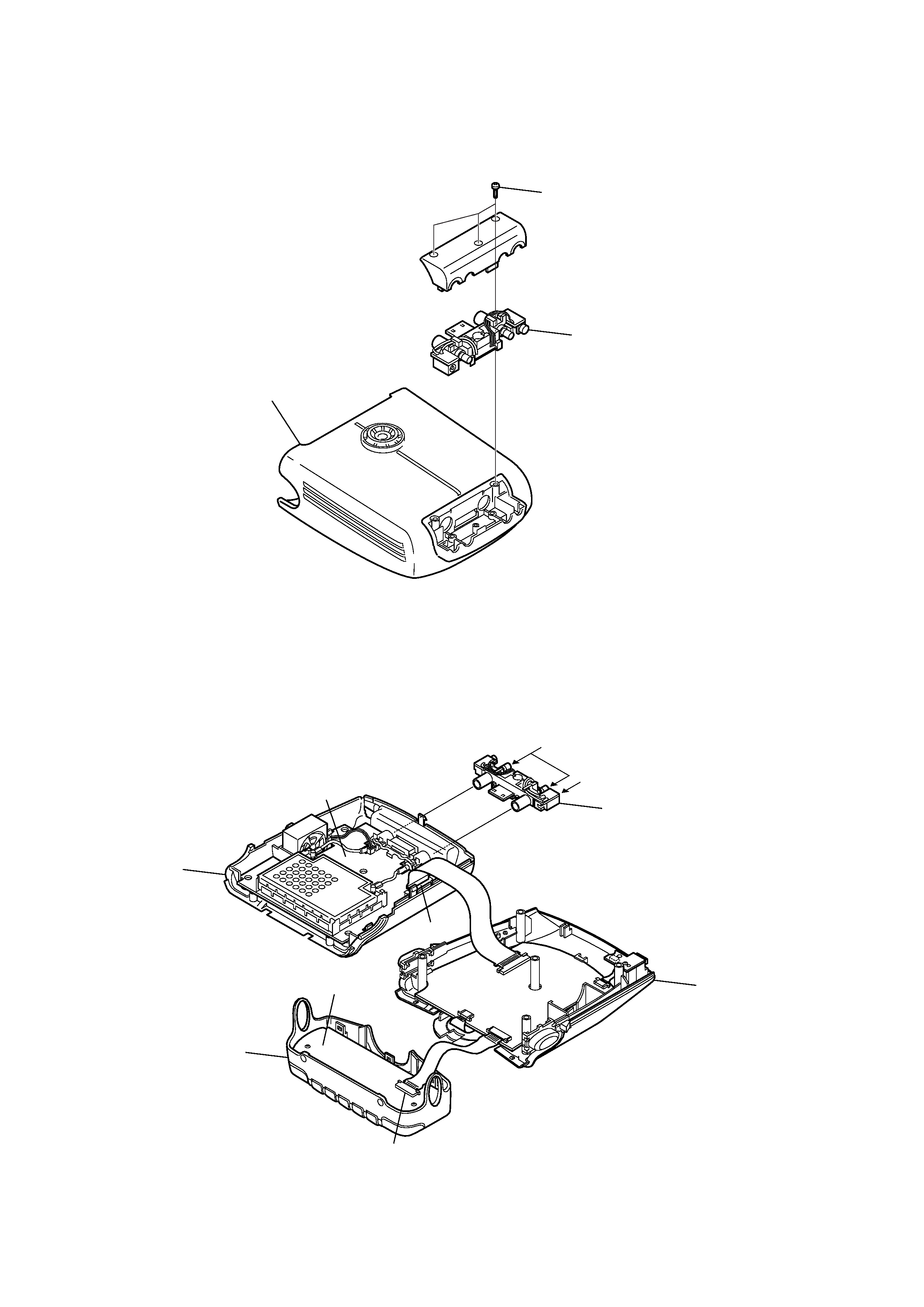
Three screws
A
Cradle
A
Upper cabinet assembly
Lower cabinet assembly
Front panel assy
LCD board
CN301
CN502
CN501
CN102
CPU board
BB board
XM Antenna
DC IN (6V)
SERVICE POSITION
· Disassemble and remove A from the cradle.
· Connect A to the set as shown below.
Then connect XM antenna and power supply.
5
DRN-XM01C/XM01R/XM01H/
XM01CK/XM01HK
SECTION 2
GENERAL
This section is extracted from
instruction manual.