1
SERVICE MANUAL
DP-IF5100
DIGITAL SURROUND PROCESSOR
SPECIFICATIONS
Modulation System
Frequency modulation
Carrier wave frequency Right channel 2.8 MHz
Left channel 2.3 MHz
Transmission distance
Approx. 10 m to the front
Transmission range
20 20,000 Hz
Distortion rate
1% or less (1 kHz)
Audio inputs
Optical input
(rectangular-type)
× 1
Analog input (pin jack
left/right)
× 1
Power requirements
DC 9 V (from the
supplied AC power
adapter)
Dimensions (w/h/d)
Approx. 85
× 190 × 180
mm (3 3/8
× 7 1/2 × 7 1/8
inch)
Mass
Approx. 1.0 kg
(1000 g) (2 lb 30 oz)
Design and specifications are subject to
change without notice.
· DP-IF5100 is the component model block one in
MDR-DS5100.
COMPONENT MODEL NAME FOR MDR-DS5100
DIGITAL SURROUND PROCESSOR
DP-IF5100
CORDLESS STEREO HEADPHONES
MDR-IF5000
· Manufactured under license from Dolby Laboratories Licensing
Corporation.
DOLBY, the double-D symbol ; , "PRO LOGIC",
"Dolby Digital (AC-3)", and "VIRTUAL DOLBY DIGITAL" are
trademarks of Dolby Laboratories Licensing Corporation.
Notes on Chip Component Replacement
· Never reuse a disconnected chip component.
· Notice that the minus side of a tantalum capacitor may be dam-
aged by heat.
US Model
Canadian Model
AEP Model
UK Model
E Model
Ver 1.1 2000. 02

2
TABLE OF CONTENTS
1. GENERAL
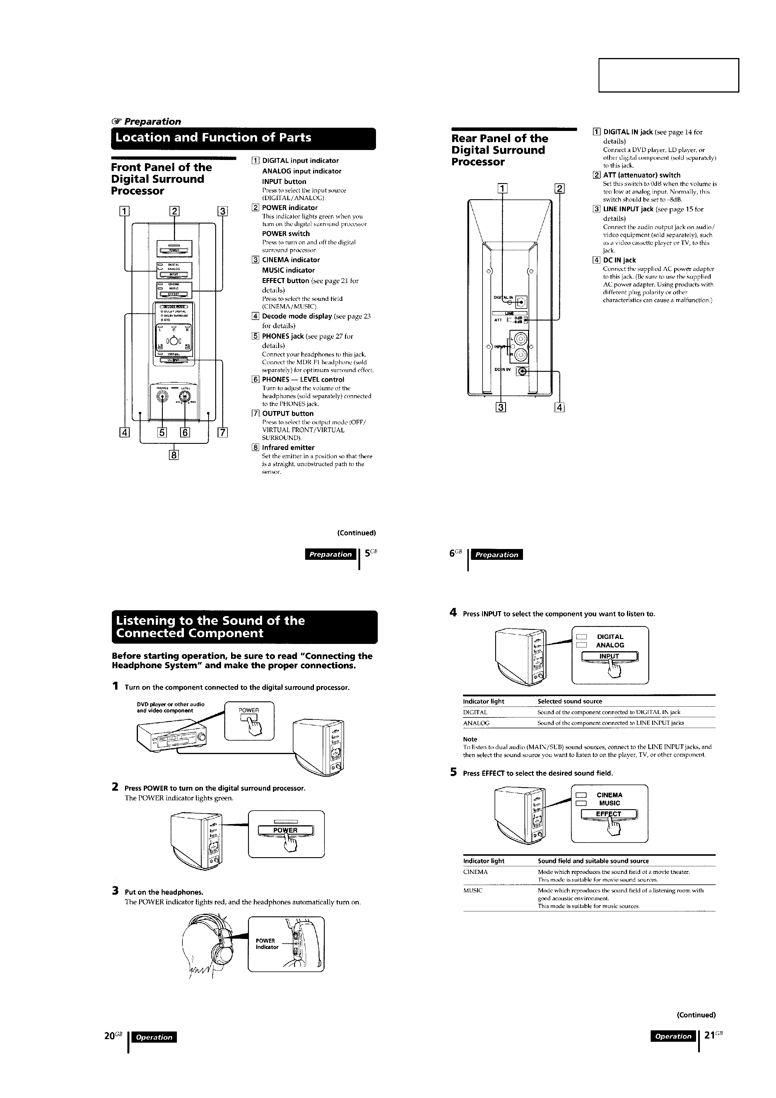
Location and Function of Parts ............................................... 3
Listening to the Sound of the Connected Component ............ 3
2. DISASSEMBLY
2-1. Cover Assy .......................................................................... 5
2-2. Panel Assy, Front ................................................................. 5
2-3. Panel Assy, Sub ................................................................... 6
2-4. TX Board ............................................................................ 6
3. SERVICE MODE
3-1. General ................................................................................ 7
3-2. Setting the Test Mode .......................................................... 7
3-3. Releasing the Test Mode ..................................................... 7
3-4. Test Mode ............................................................................ 7
4. ELECTRICAL ADJUSTMENTS ................................... 8
5. DIAGRAMS
5-1. IC Pin Descriptions ............................................................. 9
5-1-1. IC201 µPD784216 (Program, System Control) ............ 9
5-1-2. IC301 CXD9511AQ (Dolby Digital (AC-3)/
Pro Logic, DTS Decoder) ............................................ 11
5-1-3. IC302 XCB56362PV100 (24 Bit Audio Digital
Signal Processor) ......................................................... 13
5-2. Block Diagrams ................................................................ 17
5-2-1. Block Diagram Processor Section ........................... 17
5-2-2. Block Diagram Transmitter Section ........................ 19
5-3. Printed Wiring Boards and Schematic Diagrams .............. 21
5-3-1. Printed Wiring Board TX Board ............................. 21
5-3-2. Schematic Diagram TX Board (1/2) ....................... 25
5-3-3. Schematic Diagram TX Board (2/2) ....................... 27
5-3-4. Printed Wiring Board LED Board ........................... 29
5-3-5. Schematic Diagram LED Board .............................. 31
5-3-6. Printed Wiring Board AMP Board .......................... 33
5-3-7. Schematic Diagram AMP Board ............................. 34
5-4. IC Block Diagrams ........................................................... 35
6. EXPLODED VIEW ........................................................... 38
7. ELECTRICAL PARTS LIST......................................... 39
3
SECTION 1
GENERAL
This section is extracted
from instruction manual.
4
5
SECTION 2
DISASSEMBLY
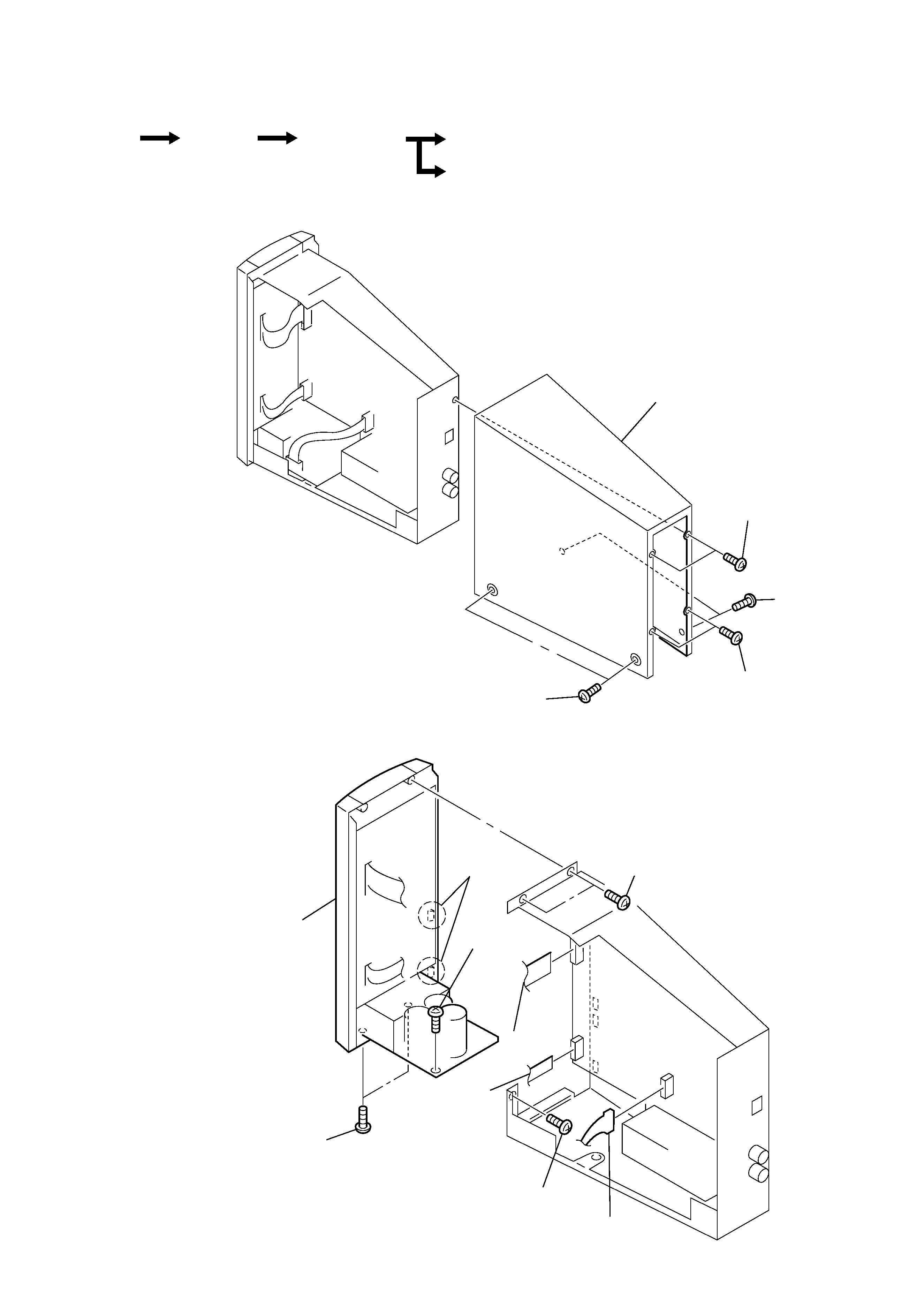
2-1. COVER ASSY
· The equipment can be removed using the following procedure.
Note : Follow the disassembly procedure in the numerical order given.
2-2. PANEL ASSY, FRONT
Set
Cover assy
Panel assy, front
Panel assy, sub
TX board
3
PTT 2.6X5
5
cover assy
2
PTT 2.6X5
4
PTT 2.6X5
1
PTT 2.6X5
4
CN103
5
CN101
6
P 3X6
7
P 3X6
3
CN102
2
PTT 2.6X5
9
panel assy, front
8
claws
1
screws (2.6x6)