1
SERVICE MANUAL
US Model
Canadian Model
AEP Model
UK Model
E Model
Tourist Model
DP-IF3000
DIGITAL SURROUND PROCESSOR
Ver 1.1 2004. 02
9-961-273-02
2004B02-1
© 2004.02
Sony Corporation
Personal Audio Company
Published by Sony Engineering Corporation
SPECIFICATIONS
· The DP-IF3000 is the digital surround
processor that comprises the MDR-
DS3000.
· MDR-DS3000 consists of the following models respectively.
Cordless stereo headphones
MDR-IF3000
Digital surround processor
DP-IF3000
Manufactured under licence from Dolby Laboratories and Digital Theater Systems, Inc.
"Dolby," "Pro Logic" and the double-D symbol
a are trademarks of Dolby Laboratories.
"DTS" and "DTS VIRTUAL " are trademarks of Digital Theater Systems, Inc.
Decoder functions
Dolby Digital
Dolby Pro Logic II
DTS
Virtual sound function
OFF
CINEMA
MUSIC
Modulation System
FM-IM (Based on IEC)
Secondary carrier wave frequency
Right channel 2.8 MHz
Left channel 2.3 MHz
Transmission distance
Approx. 7 m (23 ft.) to the front
Transmission range
20 20,000 Hz
Distortion rate
1% or less (1 kHz)
Audio inputs
Optical input
(rectangular-type) x 1
Analogue input (pin jack left/right) x 1
Power requirements
DC 9 V (from the supplied AC power
adaptor)
Dimensions
Approx. 145 x 150 x 146 mm
(5 3/4 x 6 x 5
3/
4 in.)
(w/h/d)
Mass
Approx. 370 g (14 oz.)

2
TABLE OF CONTENTS
1. GENERAL ............................................................................ 3
2. DISASSEMBLY
2-1. Cabinet (Lower) Assy, Luminous Window Assy,
IF Board ............................................................................... 5
2-2. Digital Board ........................................................................ 6
3. ELECTRICAL ADJUSTMENTS
Oscillation Frequency Adjustment .......................................... 7
RF Level Adjustment ............................................................... 7
4. DIAGRAMS
4-1. Block Diagrams ................................................................... 9
4-2. Printed Wiring Board Digital Section (Side A) ........... 10
Printed Wiring Board Digital Section (Side B) ........... 11
4-3. Schematic Diagram Digital (1/2)Section .................... 12
4-4. Schematic Diagram Digital (2/2)Section .................... 13
4-5. Printed Wiring Board IF Section ................................. 14
4-6. Schematic Diagram IF Section .................................... 15
4-7. IC Pin Function Description ............................................. 16
4-8. IC Block Diagram ............................................................. 20
5. EXPLODED VIEW
5-1. Processor Section .............................................................. 21
6. ELECTRICAL PARTS LIST ......................................... 22
DP-IF3000
Notes on Chip Component Replacement
· Never reuse a disconnected chip component.
· Notice that the minus side of a tantalum capacitor may be
damaged by heat.
r
UNLEADED SOLDER
Boards requiring use of unleaded solder are printed with the lead-
free mark (LF) indicating the solder contains no lead.
(Caution: Some printed circuit boards may not come printed with
the lead free mark due to their particular size.)
: LEAD FREE MARK
Unleaded solder has the following characteristics.
· Unleaded solder melts at a temperature about 40
°C higher than
ordinary solder.
Ordinary soldering irons can be used but the iron tip has to be
applied to the solder joint for a slightly longer time.
Soldering irons using a temperature regulator should be set to
about 350
°C.
Caution: The printed pattern (copper foil) may peel away if
the heated tip is applied for too long, so be careful!
· Strong viscosity
Unleaded solder is more viscous (sticky, less prone to flow)
than ordinary solder so use caution not to let solder bridges
occur such as on IC pins, etc.
· Usable with ordinary solder
It is best to use only unleaded solder but unleaded solder may
also be added to ordinary solder.
r
Repair DP-IF3000 with MDR-IF3000.
3
DP-IF3000
SECTION 1
GENERAL
This section is extracted
from instruction manual.
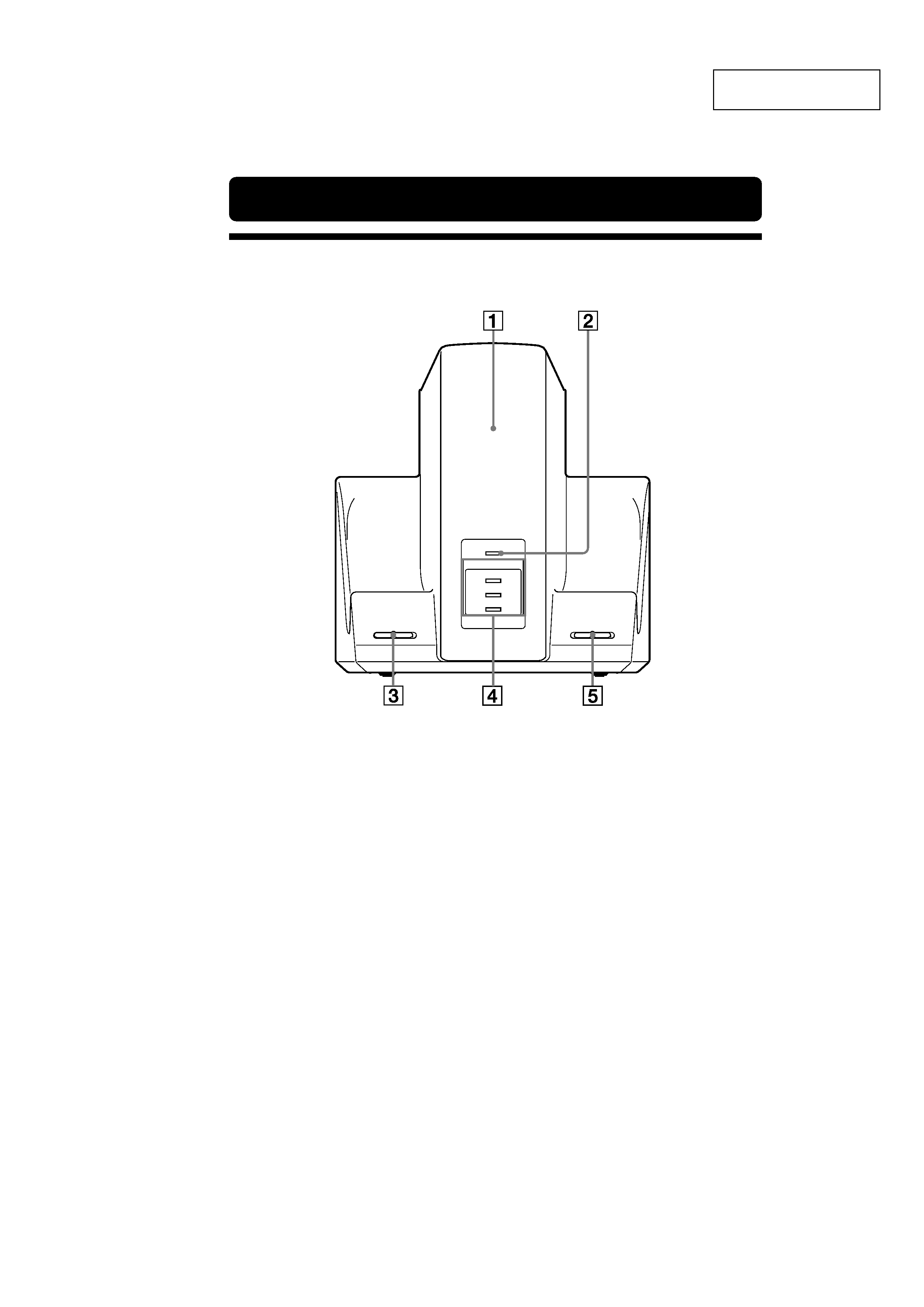
Front Panel
CHG
DECODE MODE
DOLBY DIGITAL
DOLBY PRO LOGIC II
DTS
ANALOG
DIGITAL
INPUT SELECT
MUSIC
CINEMA
OF F
EFFECT
Location and Function of Parts
1
Infrared emitte r
Set the emitter in a position so that there
is a straight, unobstructed path to the
sensor.
2
CHG indicator
Lights red while charging.
3
INPUT SE LECTswitch
Slide to select the input source
(DIGITAL/ANALOG) .
4
DECODE MODE indica tor
5
EFFECT switch
Slide to select the sound field (OFF/
CINEMA/MUSIC).
4
DP-IF3000
This section is extracted
from instruction manual.
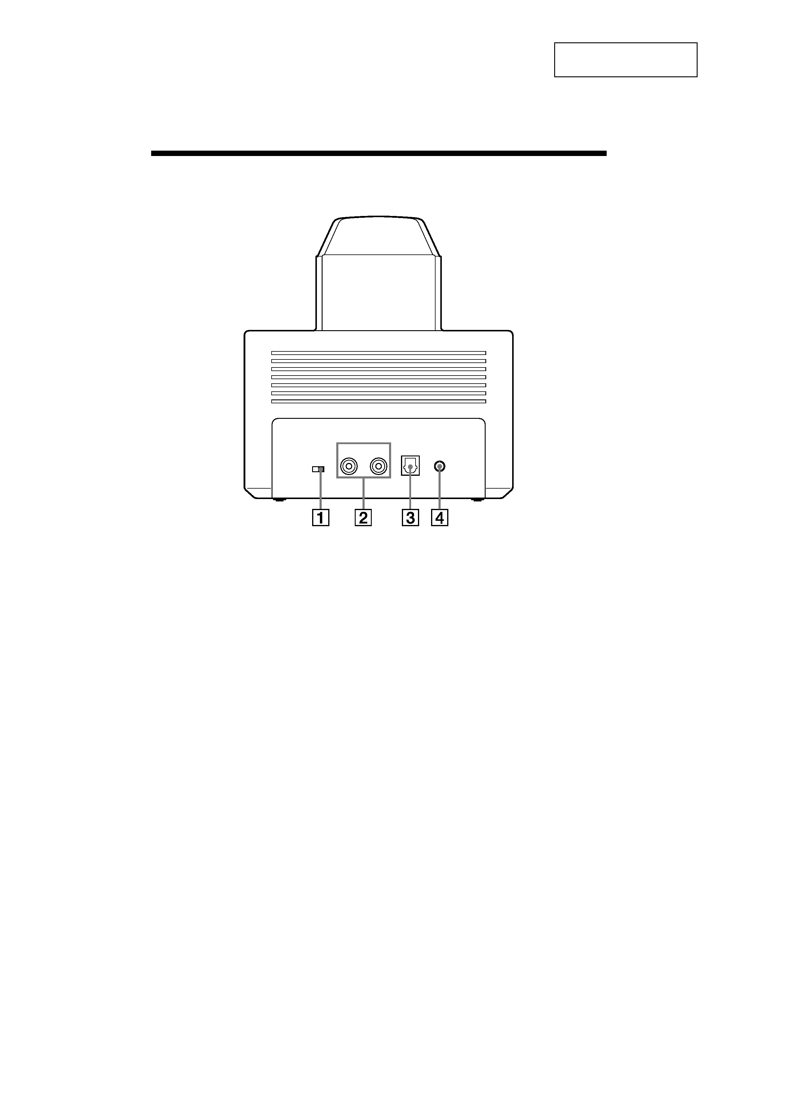
Rear Pane l
LINE IN
ATT
DIGITAL IN
L
DC IN 9V
R
0dB- 8dB
1
ATT (attenu ator) switch
Set this switch to "0dB" if the volume is
too low at analogue input. Normally, this
switch should be set to "-8dB"
2
LINE IN jacks
Connect the audio output jacks on audio
or video component (sold separately),
such as a video cassette player or TV, to
these jacks.
3
DIGITAL IN jack
Connect a DVD player, or other digital
component (sold separately) to this jack.
4
DC IN 9V jack
Connect the supplied AC power adaptor
to this jack. (Be sure to use the supplied
AC power adaptor. Using products with
different plug polarity or other
characteristics can cause a malfunction.)
5
DP-IF3000
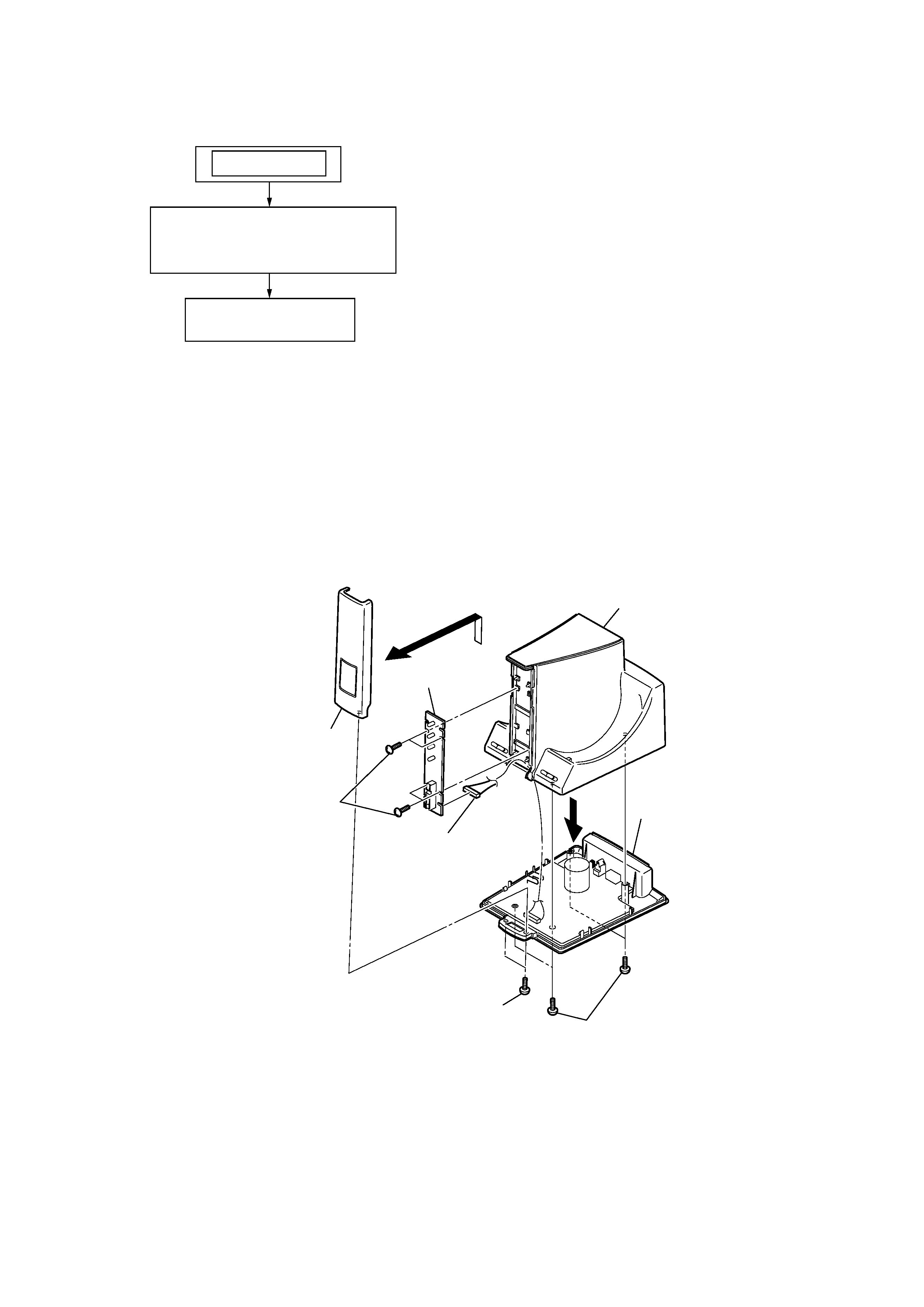
Note : This set can be disassemble according to the following sequence.
SECTION 2
DISASSEMBLY
2-1. CABINET (LOWER) ASSY, LUMINOUS WINDOW ASSY, IF BOARD
Note : Follow the disassembly procedure in the numerical order given.
CABINET (LOWER) ASSY,
LUMINOUS WINDOW ASSY,
IF BOARD
SET
DIGITAL BOARD
3
6
2
two screws (+B2.6)
8
four screws (+B2.6)
4
connector (CN501)
1
four screws (+B2.6)
5
cabinet (lower) assy
9
IF board
cabinet (upper)
7
luminous window assy