DPA-300
US Model
Canadian Model
SERVICE MANUAL
DIGITAL STILL RECORDER
MICROFILM
Model Name Using Similar Mechanism
NEW
MD Mechanism Type
MDM-2BR
Base Unit Name
MBU-2
Optical Pick-up Name
KMS-210A/J-N
U.S and foreign patents licensed from Dolby Laboratories
Licensing Corporation.
-- Continued on next page --
SPECIFICATIONS
System
Recording format
Picture MD recording system
Data compression/saving system
JPEG
FINE mode : 128kB
(the maximum 1,000 images)
STANDARD mode : 64kB
(the maximum 2,000 images)
Revolutions
400 rpm to 900 rpm (CLV)
Error correction
Advanced Cross Interleave Reed
Solomon Code (ACIRC)
Laser
Semiconductor laser (
= 780 nm)
Emission duration : continuous
Laser output
Max 44.6 µW
* This output is the value measured at a
distance of 200 mm from the objective lens
surface on the Optical Pick-up Block with
7 mm aperture.
Sampling frequency
44.1 kHz
Coding
Adaptive TRansform Acoustic Coding
(ATRAC)
Modulation system
EFM (Eight to Fourteen Modulation)
Number of channels
2 stereo channels
Input
VIDEO INPUT
Input signal : 1Vp-p
(75
unbalanced)
Y/C INPUT, Mini DIN 4-pin
Luminance signal : 1Vp-p
(75
unbalanced)
Chrominance signal : 0.286 Vp-p
(75
unbalanced)
AUDIO IN (L/R)
Input level : 2 Vrms (full bit)
Input impedance : more than 47 k
FS1/FS2 (RED/WHITE) connectors
Output
VIDEO OUTPUT
Output signal : 1 Vp-p
(75
unbalanced)
Y/C OUTPUT, Mini DIN 4-pin
Luminance signal : 1 Vp-p
(75
unbalanced)
Chrominance signal : 0.286 Vp-p
(75
unbalanced)
AUDIO OUT (L/R)
Output level : 2 Vrms (full bit)
Output impedance : more than 47 k
-- 2 --
SAFETY-RELATED COMPONENT WARNING!!
COMPONENTS IDENTIFIED BY MARK ! OR DOTTED LINE WITH
MARK ! ON THE SCHEMATIC DIAGRAMS AND IN THE PARTS
LIST ARE CRITICAL TO SAFE OPERATION. REPLACE THESE
COMPONENTS WITH SONY PARTS WHOSE PART NUMBERS
APPEAR AS SHOWN IN THIS MANUAL OR IN SUPPLEMENTS
PUBLISHED BY SONY.
ATTENTION AU COMPOSANT AYANT RAPPORT
À LA SÉCURITÉ!
LES COMPOSANTS IDENTIFÉS PAR UNE MARQUE ! SUR LES
DIAGRAMMES SCHÉMATIQUES ET LA LISTE DES PIÈCES SONT
CRITIQUES POUR LA SÉCURITÉ DE FONCTIONNEMENT. NE
REMPLACER CES COMPOSANTS QUE PAR DES PIÈSES SONY
DONT LES NUMÉROS SONT DONNÉS DANS CE MANUEL OU
DANS LES SUPPÉMENTS PUBLIÉS PAR SONY.
After correcting the original service problem, perform the following
safety checks before releasing the set to the customer:
Check the antenna terminals, metal trim, "metallized" knobs, screws,
and all other exposed metal parts for AC leakage. Check leakage as
described below.
LEAKAGE
The AC leakage from any exposed metal part to earth ground and
from all exposed metal parts to any exposed metal part having a
return to chassis, must not exceed 0.5 mA (500 microamperes).
Leakage current can be measured by any one of three methods.
1.
A commercial leakage tester, such as the Simpson 229 or RCA
WT-540A. Follow the manufacturers' instructions to use these
instruments.
2.
A battery-operated AC milliammeter. The Data Precision 245
digital multimeter is suitable for this job.
3.
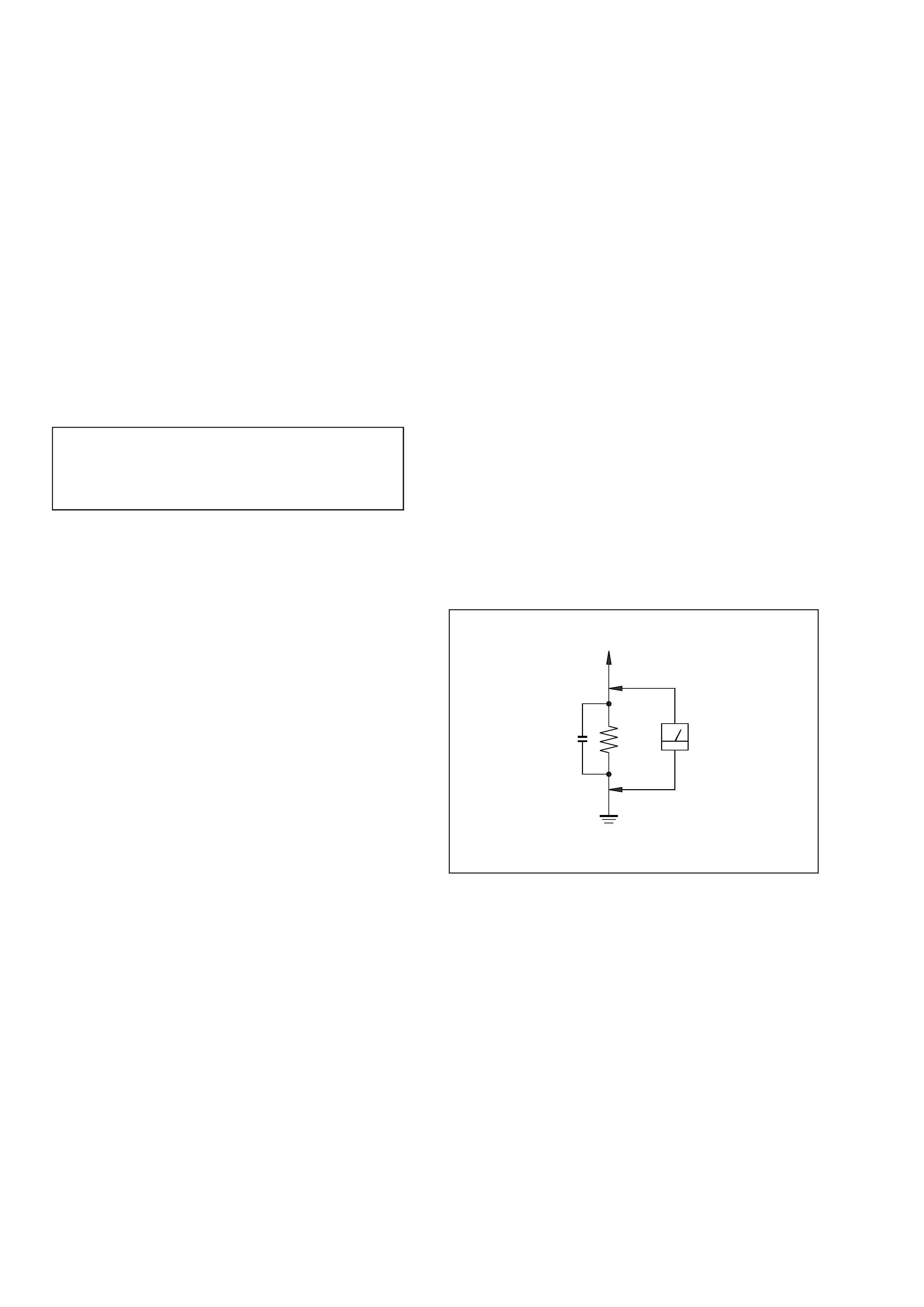
Measuring the voltage drop across a resistor by means of a
VOM or battery-operated AC voltmeter. The "limit" indication
is 0.75 V, so analog meters must have an accurate low-voltage
scale. The Simpson 250 and Sanwa SH-63Trd are examples of
a passive VOM that is suitable. Nearly all battery operated
digital multimeters that have a 2V AC range are suitable. (See
Fig. A)
SAFETY CHECK-OUT
To Exposed Metal
Parts on Set
0.15
µF
1.5k
AC
voltmeter
(0.75V)
Earth Ground
Fig. A. Using an AC voltmeter to check AC leakage.
General
Power requirements
Sony AC Power Adaptor AC-DA300
(supplied) connected at the DC IN 12 V
jack : 120V AC, 60Hz (US model)
Power consumption
20 W
Operating temperature
5
°C to 35 °C (41°F to 95°F)
Operating humidity
30% to 85%
Dimensions
Approx. 280
× 80 × 290 mm
(11
1/8
× 31/4 × 111/2 inches)
(w/h/d, including projecting parts and
controls)
Mass
Approx. 2.5 kg (5 lb. 8 oz)
Supplied accessories
AC power adaptor AC-DA300
Remote commander RMT-DA300 (1)
Size AA (R6) batteries (2)
Design and specifications are subject to change without notice.
Notes on chip component replacement
· Never reuse a disconnected chip component.
· Notice that the minus side of a tantalum capacitor may be
damaged by heat.
Flexible Circuit Board Repairing
· Keep the temperature of soldering iron around 270°C
during repairing.
· Do not touch the soldering iron on the same conductor of the
circuit board (within 3 times).
· Be careful not to apply force on the conductor when soldering
or unsoldering.
CAUTION
Danger of explosion if battery is incorrectly replaced.
Replace only with the same or equivalent type recommended by
the manufacturer.
Discard used batteries according to the manufacturer's instructions.
CAUTION
Use of controls or adjustments or performance of procedures
other than those specified herein may result in hazardous
radiation exposure.

-- 3 --
TABLE OF CONTENTS
1. SERVICING NOTE ·························································· 4
2. GENERAL ·········································································· 7
3. DISASSEMBLY
3-1.
Upper Case ································································· 11
3-2.
Front Panel, Panel Board and Video In Board ··········· 11
3-3.
Picture Board, Power Board and Mechanism Deck
···················································································· 12
3-4.
MD Mechanism Deck ················································ 13
3-5.
Slider (MD Mechanism) ············································ 13
3-6.
MD Base Unit (MBU-2) and Loading Motor Assy ··· 14
3-7.
How to Attach the Slider (MD Mechanism) ·············· 14
4. TEST MODE ···································································· 15
5. ELECTRICAL ADJUSTMENTS ······························· 18
6. DIAGRAMS
6-1.
Circuit Board Location ··············································· 28
6-2.
Block Diagram -- BD Section -- ······························ 29
6-3.
Block Diagram -- MD Control Section -- ··············· 31
6-4.
Block Diagram -- Video Control Section -- ············ 33
6-5.
Block Diagram -- Video Process Section -- ············ 35
6-6.
Block Diagram -- IR Section -- ······························· 37
6-7.
Block Diagram -- Video Out Section -- ··················· 39
6-8.
Block Diagram -- Video In Section -- ····················· 41
6-9.
Block Diagram -- Audio Section -- ························· 43
6-10. Block Diagram -- Power Section -- ························· 45
6-11. Printed Wiring Board -- Picture Section -- ·············· 47
6-12. Schematic Diagram -- Picture Section (1/3) -- ········ 51
6-13. Schematic Diagram -- Picture Section (2/3) -- ········ 55
6-14. Schematic Diagram -- Picture Section (3/3) -- ········ 59
6-15. Printed Wiring Board -- BD Section -- ···················· 62
6-16. Schematic Diagram -- BD Section -- ······················ 65
6-17. Schematic Diagram -- Video In Section -- ·············· 69
6-18. Printed Wiring Board -- Video In Section -- ··········· 73
6-19. Printed Wirimg Board -- MD Section -- ·················· 77
6-20. Schematic Diagram -- MD Section (1/2) -- ············· 81
6-21. Schematic Diagram -- MD Section (2/2) -- ············· 85
6-22. Printed Wiring Board -- Power Section -- ··············· 89
6-23. Schematic Diagram -- Power Section -- ·················· 91
6-24. Printed Wiring Board -- Panel Section -- ················ 94
6-25. Schematic Diagram -- Panel Section -- ··················· 97
6-26. IC Block Diagrams ····················································· 99
6-27. IC Pin Function ························································ 111
7. EXPLODED VIEWS
7-1.
Upper Case Section ·················································· 144
7-2.
Front Panel Section ·················································· 145
7-3.
Bottom Cabinet Section ··········································· 146
7-4.
Mechanism Section (MDM-2BR) ···························· 147
7-5.
Base Unit Section (MBU-2) ····································· 148
8.
ELECTRICAL PARTS LIST ································· 149
-- 4 --
SECTION 1
SERVICING NOTE
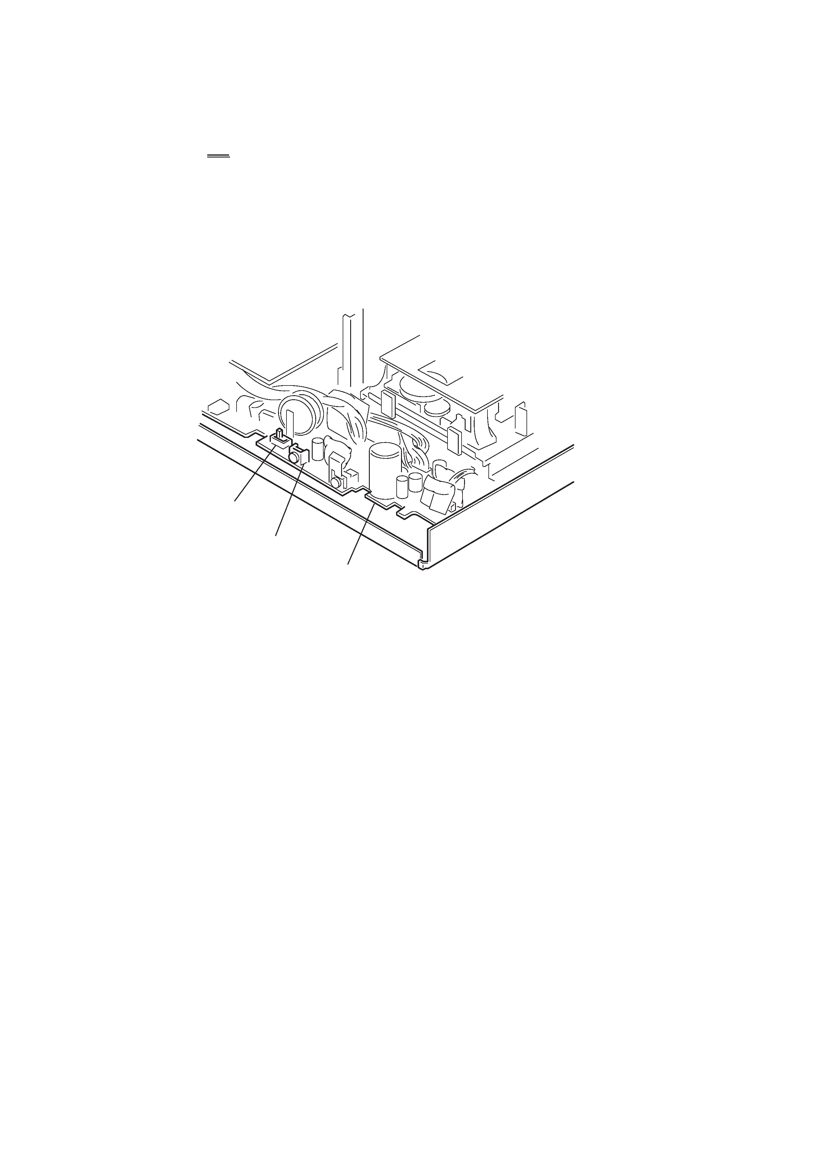
[About Switches on POWER Board]
· Backup Power ON/OFF Switch (S1351 B. UP ON)
Be sure to turn this switch to OFF when removing and inserting connectors to and from the circuit boards.
This switch protects semiconductors from breakdown due to static electricity.
Set this switch to ON during normal operation. The DPA-300 does not work unless this switch is set to ON.
· Reset Switch (S1352 RESET)
This switch resets forcibly system of DPA-300. Press the reset switch when microprocessor runs away, or when DPA-300 does not
operate normally, or when the main power is desired to turn ON, OFF and back ON momentarily during test mode, etc.
Rear Side
S1351
(B.UP ON)
S1352
(RESET)
POWER board
-- 5 --
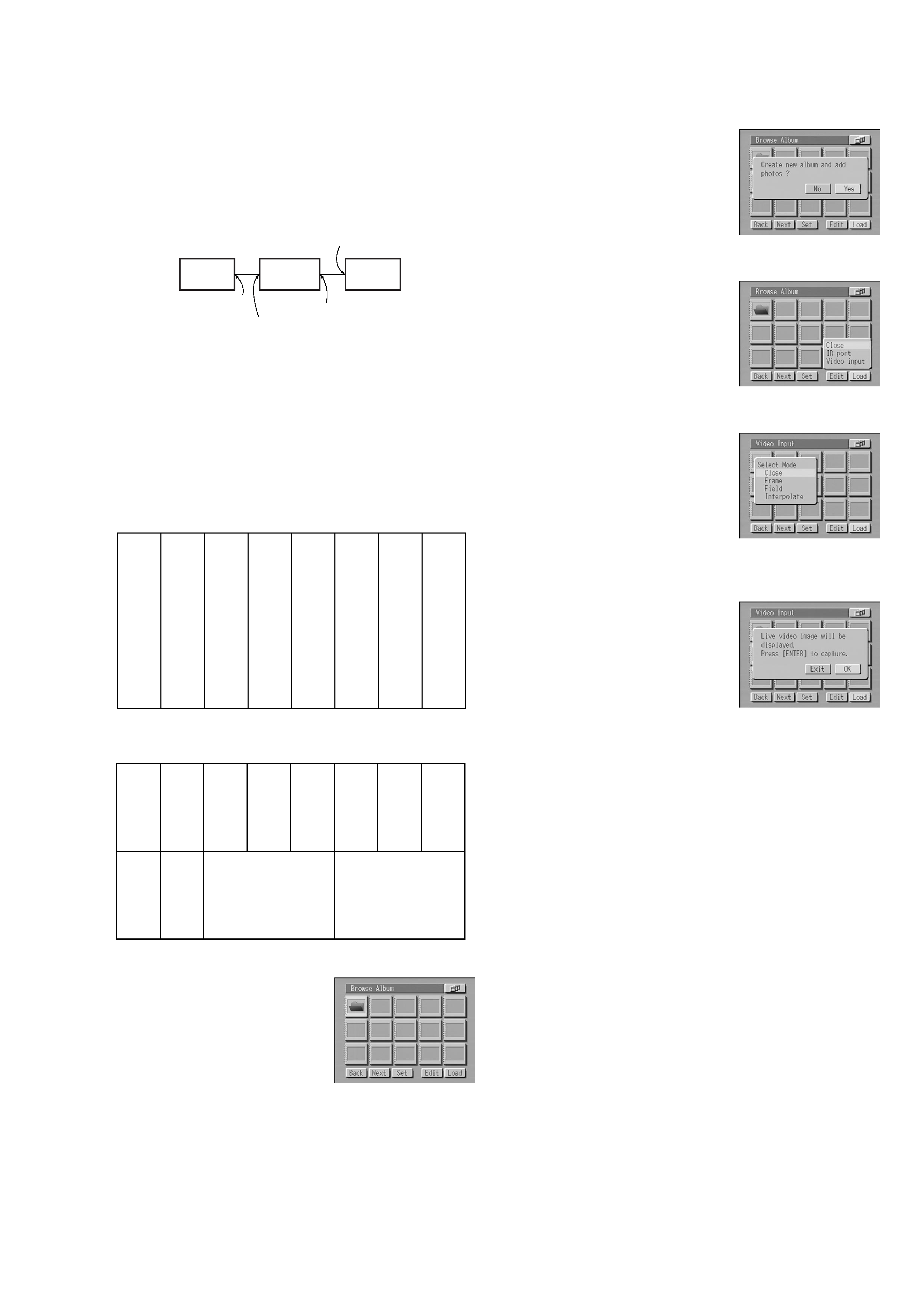
[How to Set the Mode Displaying the Through Picture]
Input the color bar signal and enter this mode as follows to check
the DPA-300 for voltages, waveforms and to implement a part of
adjustments.
Connection:
When the equipment connection is completed, set up this mode by
following the procedures in the order given below.
1. Turn the main power ON. (Turn on the main power of color
bar generator, DPA-300 and monitor.)
2. Connect the color bar signal to video input.
Color bar signal specifications to be input
Color bar signal for voltage and waveform measurement
Color bar signal for adjustment
3. Insert the MD data disc.
List of album appears.
When the MD data disc has not been formatted, format it.
4. Select "Load" using the f F g G button and press the ENTER
button.
The message "Create new album
and add photos?" appears.
5. Select "Yes" using the f F g G button and press the ENTER
button.
The new album to load the pictures
are created. When an album is
created, the loading menu appears.
6. Select "Video input" using the g G button and press the ENTER
button.
The display from which the modes
can be selected, appears
7. Select "Frame" using the g G button and press the ENTER
button.
Mode differs depending on the type
of input signal supplied from the
video equipment connected.
8. Select "OK" using the f F g G button and press the ENTER
button.
9. Color bars supplied to the Video Input connector, appear on
monitor when the ENTER button is pressed.
Note : When the ENTER button is pressed in the state of step 9, the
picture is loaded and the DPA-300 exits the Through mode.
When the ENTER button is pressed incorrectly, follow the
instruction shown on the monitor screen and return to the
state of step 9.
DPA-300
Color bar generator
Output
Input
Video Output
Video Input or
S-Video Input
monitor
WHITE
(75%)
YELLOW
CY
AN
GREEN
MAGENT
A
RED
BLUE
BLACK
WHITE
(75%)
YELLOW
CY
AN
GREEN
MAGENT
A
RED
BLUE
BLACK
Q
I
WHITE (100%)
BLACK