SERVICE MANUAL
COLOUR PRINTER
AEP Model
SPECIFICATIONS
DMP-1000P
9-928-154-11
Printer section
Printing system
Sublimation dye transfer printing
(Yellow/Magenta/Cyan 3 pass)
Effective pixels
1,376 (H)
× 1,024 (V) dot
Printing size
114 (H)
× 85 (V) mm (maximum)
(41/
2 × 3
3/
8 inches)
Gradations
256 levels (8 bits), per colour (24 bits)
Approx. 16,770,000 colours
Printing time (excluding data transmission time)
Approx. 100 seconds per sheet
Input/output connectors
VIDEO INPUT connector (phono jack
× 1)
1 Vp-p, 75 ohms (unbalanced),
sync nagative
S VIDEO INPUT connector
(4-pin mini-DIN
× 1)
Y: 1 Vp-p, 75 ohms (unbalanced),
sync negative
C: 0.286 Vp-p (colour burst),
75-ohms (unbalanced)
VIDEO OUTPUT connector
(phono jack
× 1)
1 Vp-p, 75 ohms (unbalanced),
sync negative
3.5" Floppy disk drive
Print cartridge and Print paper (100
× 140 mm (4 × 55/
8 inches))
DPM-50STA (Standard papers)
Power requirements
220 - 240 V AC, 50/60 Hz, 0.6 A
Power consumption
72 W (printing)
13 W (stand by mode)
Operating temperature
5
°C to 35 °C (41 °F to 95 °F)
Dimensions
Approx. 301
× 83 × 246 mm
(w/h/d, excluding protruding parts)
(12
× 33/
8 × 9
7/
8 inches)
Mass
Approx. 3 kg (6 lb 10 oz)
Supplied accessories
AC power cord (1)
Automatic feeder (1)
Video connecting cable (1)
BNC-PIN cable adapter (2)
Instruction Manual (1)
Warranty (1)
Automatic feeder section
Maximum Printing Quantity
25 sheets
(1, 2, 3, 4, 5, 10, 25 selectable)
Print paper
VP-standard print paper
(100
× 140 mm (4 × 5 5/8 inches) (v/h),
cut paper)
Operating temperatures
5
°C to 35 °C (41 °F to 95 °F)
Dimensions
Approx. 149
× 32 × 185 mm
(5 7/8
× 1 5/16 × 7 3/8 inches) (w/h/d)
excluding projecting parts
Mass
Approx. 360 g (13 oz)
Design and specifications are subject to change without notice.
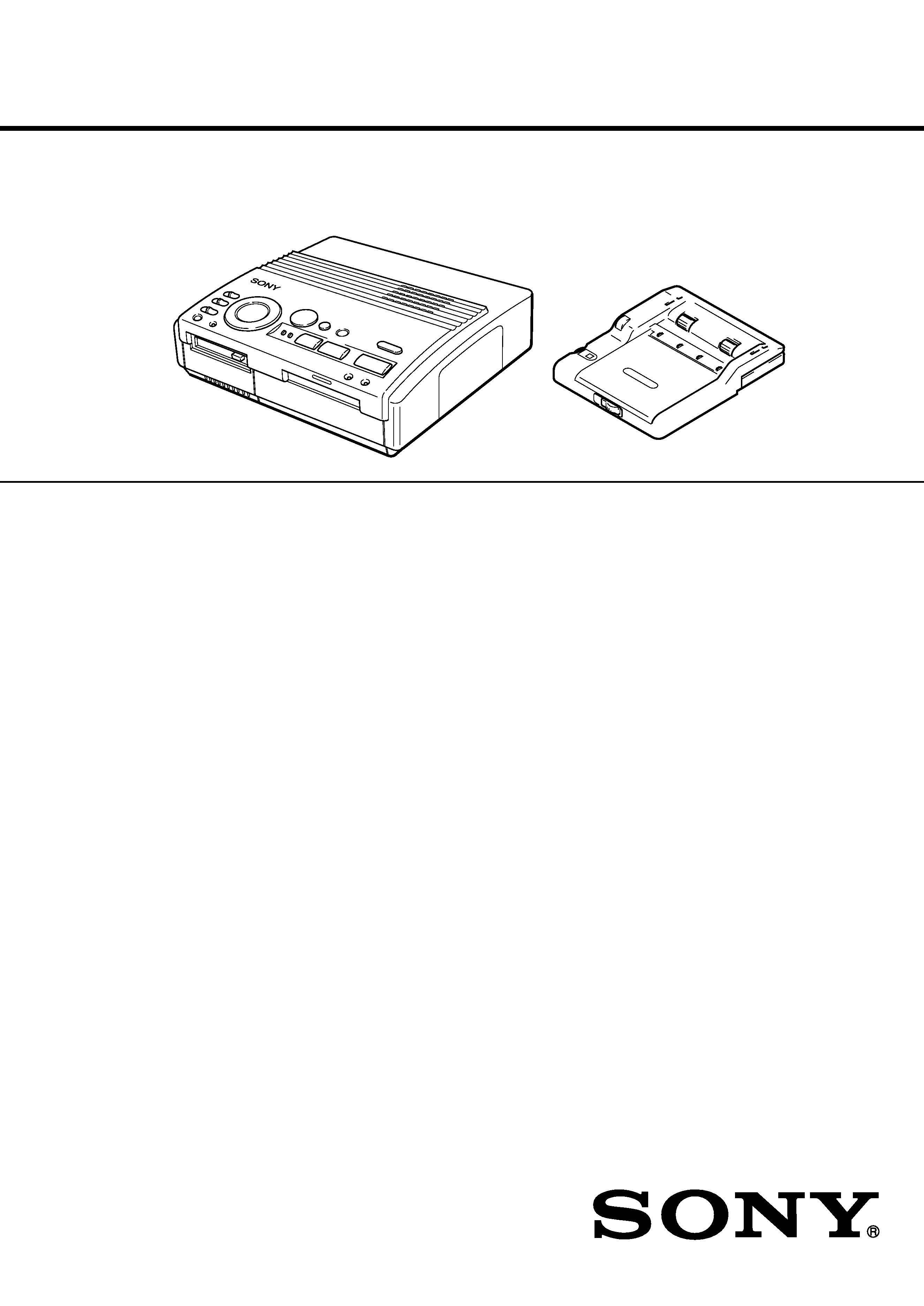
Printer Section
Automatic Feeder Section

2
Confidential
DMP-1000P (AEP)
TABLE OF CONTENTS
1.
GENERAL
Identifying the Parts ..................................................... 1-1
Setting Up .................................................................... 1-1
Printing ......................................................................... 1-4
Making Various Prints .................................................. 1-6
For Your Information ................................................... 1-9
2.
DISASSEMBLY ...................................................... 2-1
3.
MECHANICAL ADJUSTMENTS .................... 3-1
4.
ELECTRICAL ADJUSTMENTS ...................... 4-1
5.
DIAGRAMS
5-1.
Block Diagram VIDEO Section ........................... 5-1
5-2.
Block Diagram MAIN Section ............................. 5-3
5-3.
Block Diagram FLOPPY DISK DRIVE
CONTROL/EEPROM Section ................................. 5-5
5-4.
Block Diagram HEAD/SENSOR/MOTOR/
POWER SUPPLY Section ........................................ 5-7
5-5.
Frame Schematic Diagram .......................................... 5-9
5-6.
Notes for Printed Wiring Board and
Schematic Diagram ...................................................... 5-12
5-7.
Printed Wiring Board VS-39 Board ..................... 5-13
5-8.
Schematic Diagram VS-39 Board ......................... 5-13
5-9.
Printed Wiring Board FE-39 Board ....................... 5-14
5-10. Schematic Diagram FE-39 Board .......................... 5-14
5-11. Printed Wiring Board VI-39 Board ...................... 5-15
5-12. Schematic Diagram VI-39 Board .......................... 5-17
5-13. Printed Wiring Board DK-39E Board .................. 5-23
5-14. Schematic Diagram DK-39E Board (1/3) ............. 5-25
5-15. Schematic Diagram DK-39E Board (2/3) ............. 5-30
5-16. Schematic Diagram DK-39E Board (3/3) ............. 5-35
5-17. Printed Wiring Board SW-39 Board .................... 5-37
5-18. Schematic Diagram SW-39 Board ........................ 5-39
5-19. Printed Wiring Boards
MD-39/JD-39/RD-39/HP-39 Boards .................... 5-41
5-20. Schematic Diagram
MD-39/JD-39/RD-39/HP-39 Boards .................... 5-43
5-21. Printed Wiring Boards
Automatic Feeder Section ...................................... 5-46
5-22. Schematic Diagram
Automatic Feeder Section ...................................... 5-47
5-23. IC Pin Function Description ........................................ 5-53
6.
EXPLODED VIEWS ............................................. 6-1
7.
ELECTRICAL PARTS LIST ............................ 7-1
Flexible Circuit Board Repairing
· Keep the temperature of the soldering iron around 270 °C dur-
ing repairing.
· Do not touch the soldering iron on the same conductor of the
circuit board (within 3 times).
· Be careful not to apply force on the conductor when soldering
or unsoldering.
Notes on chip component replacement
· Never reuse a disconnected chip component.
· Notice that the minus side of a tantalum capacitor may be dam-
aged by heat.
SAFETY-RELATED COMPONENT WARNING!!
COMPONENTS IDENTIFIED BY MARK 0 OR DOTTED
LINE WITH MARK 0 ON THE SCHEMATIC DIAGRAMS
AND IN THE PARTS LIST ARE CRITICAL TO SAFE
OPERATION. REPLACE THESE COMPONENTS WITH
SONY PARTS WHOSE PART NUMBERS APPEAR AS
SHOWN IN THIS MANUAL OR IN SUPPLEMENTS PUB-
LISHED BY SONY.
ADVARSEL
Eksplosjonsfare ved feilaktig skifte av batteri.
Benytt samme batteritype eller en tilsvarende type
anbefalt av apparatfabrikanten.
Brukte batterier kasseres i henhold til fabrikantens
instruksjoner.
VARNING
Explosionsfara vid felaktigt batteribyte.
Använd samma batterityp eller en likvärdig typ som
rekommenderas av apparattillverkaren.
Kassera använt batteri enligt gällande föreskrifter.
VAROITUS
Paristo voi räjähtää, jos se on virheellisesti asennettu.
Vaihda paristo ainoastaan laitevalmistajan suosittelemaan tyyppiin.
Hävitä käytetty paristo valmistajan ohjeiden mukaisesti.
ADVARSEL!
Lithiumbatteri-Eksplosionsfare ved fejlagtig håndtering.
Udskiftning må kun ske med batteri
af samme fabrikat og type.
Levér det brugte batteri tilbage til leverandøren.
CAUTION
Danger of explosion if battery is incorrectly replaced.
Replace only with the same or equivalent type recommended by
the manufacturer.
Discard used batteries according to the manufacturer's instruc-
tions.
1-1
Confidential
DMP-1000P (AEP)
SECTION 1
GENERAL
This section is extracted from
instruction manual.
6GB
Getting Started
1
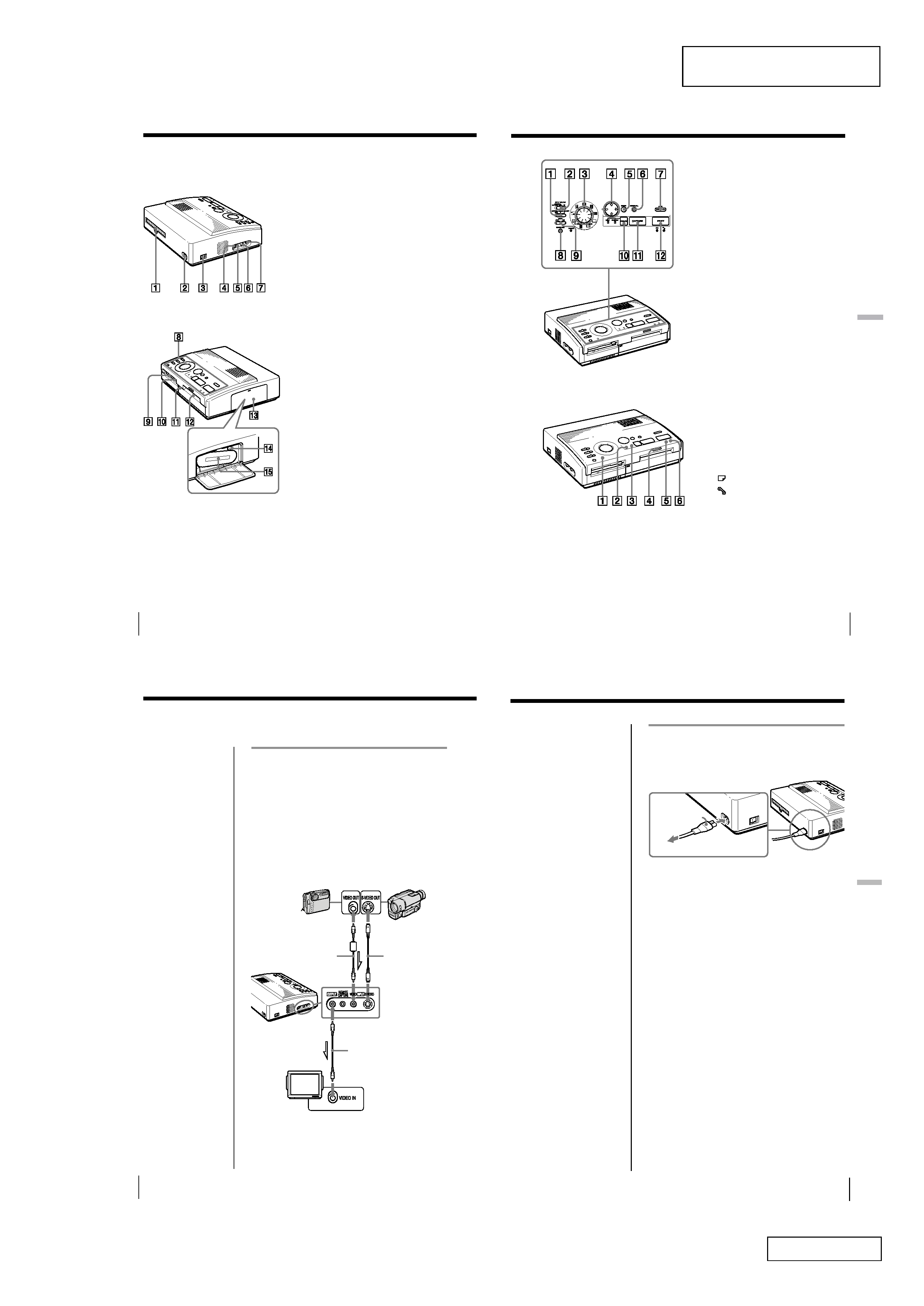
Paper outlet (page 47)
2
AC power connector (page 9)
3
POWER switch (page 10)
4
VIDEO OUTPUT connector (page 8,
19)
5
REMOTE CAPTURE jack (page 39)
6
VIDEO INPUT connector (page 8)
7
S VIDEO INPUT connector (page 8)
8
Operation panel (page 7)
9
3.5-inch floppy disk insertion slot
(page 19)
0
3.5-inch floppy disk eject button
(page 19)
qa
Cover for the automatic feeder
(page 17)
qs
Paper inlet/outlet for manual
feeding (page 17, 47)
qd
Cartridge door (page 13, 14)
qf
Eject lever (page 14)
qg
Print cartridge (page 13, 14) (not
supplied)
Cartridge compartment
See the pages given in parentheses for use of the parts.
Identifying the parts
Identifying the parts
7GB
Getting
Started
Getting Started
Operation Panel
1
MIRROR IMAGE SELECT switch
(page 30)
2
INPUT SELECT switch (page 20, 23)
3
Print mode dial (page 21, 24, 26, 28,
32, 34)
4
Arrow buttons (B/b/V/v) (page
24)
5
ENTER button (page 24)
6
CLEAR ALL button (page 21)
7
SAVE button (page 36)
8
CLOCK SET button (page 10)
9
DATE switch (page 38)
0
PICTURE button (page 23, 25)
qa
CAPTURE button (page 21, 24)
qs
PRINT button (page 22, 25)
Indicators
1
POWER indicator (page 10)
2
INPUT indicator (page 21, 45)
3
MEMORY indicator (page 21, 45)
4
Print indicator (page 22, 25, 45)
5
Paper supply indicator (page 45)
6
Ribbon error indicator (page 45)
8GB
Setting Up
If the video equipment
has the S-video output
connector
Connect it to the S VIDEO
INPUT connector of the
printer using the optional
S-video connecting cable
so that you can get better
picture quality. In this
case, you do not need to
connect the video
connector.
When both the S VIDEO
INPUT and VIDEO INPUT
connectors of the
printer are connected
The input signals from
the S VIDEO INPUT
connector are
automatically selected.
Notes
· Before making
connections, turn off
the power of the
printer, the video
equipment and
television.
· See also to the
instruction manuals for
the video equipment.
Connecting to the video equipment
When printing images from the video equipment such
as a VCR or camcorder, use the supplied video
connecting cable to connect the video equipment and
the printer. Also connect the printer to the television to
display the images to be printed.
For printing operations, see page 20.
Television
Set input selector to
"VIDEO."
Video connecting
cable (supplied)
S-video connecting
cable (not
supplied)
Video connecting
cable (not supplied)
Video camera or
etc. equipped with
the S-video output
connector
Digital still camera or
video camera
equipped with the
video output
connector
Or
Setting Up
Connecting the printer
To VIDEO OUTPUT
To S VIDEO
INPUT
To VIDEO
INPUT
l : Signal flow
9GB
Setting Up
Setting
Up
Connecting the AC power cord
After you make connections, connect the supplied AC
power cord to the AC power connector of the printer
and then to the AC outlet.
To the AC outlet
AC Power cord
(supplied)
1-2
Confidential
DMP-1000P (AEP)
10GB
Setting Up
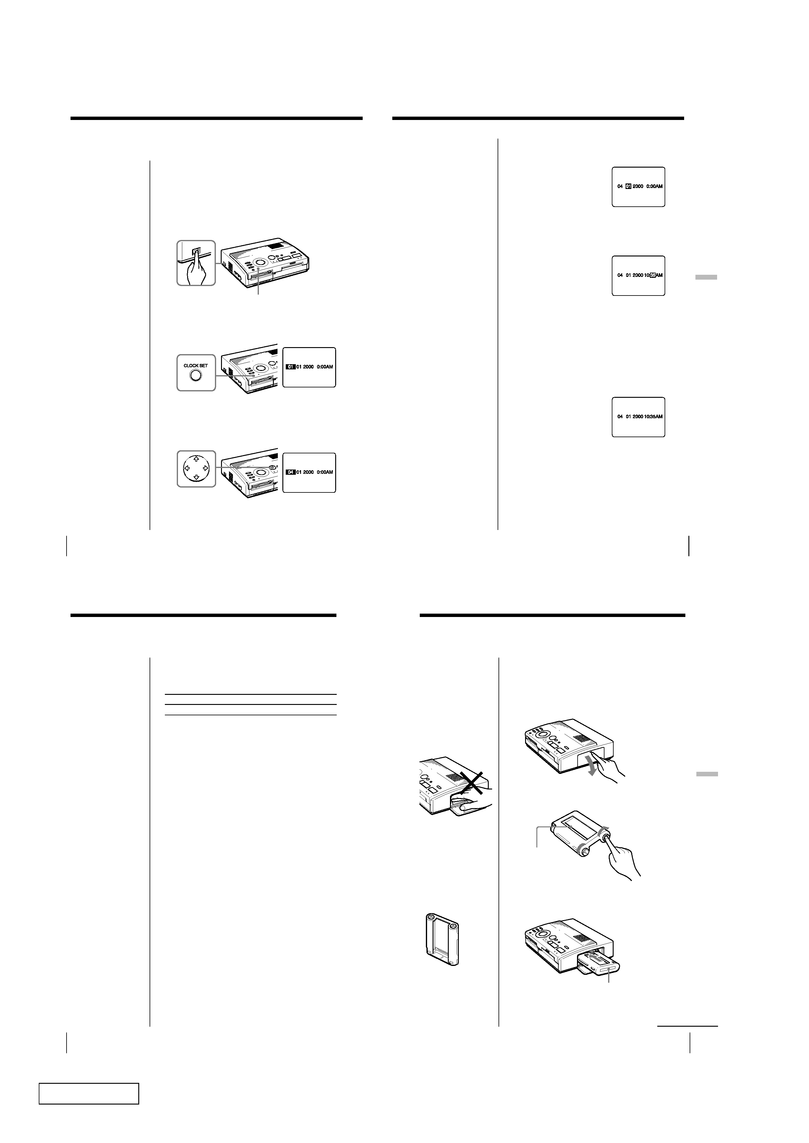
Adjusting the clock
You can save the time when the images are captured
from the video equipment by adjusting the clock of the
printer. Once you adjust the clock, the clock is
maintained with the battery even if you turn off the
power.
1 Turn on the power of the printer.
The POWER indicator lights up.
2 Press and hold CLOCK SET, then press b.
The clock setting display appears on the television.
3 Press V/v to set the month.
Pressing V increases the number.
Pressing v decreases the number.
POWER indicator
POWER switch
11GB
Setting Up
Setting
Up
4 Press b.
The cursor moves to the next item.
5 Repeat steps 3 and 4 to set all items: month, date,
year, hour and minute.
If you want to set the previous item, press B.
6 Press CLOCK SET.
The clock setting display disappears.
Displaying the clock
When the INPUT indicator is on, press CLOCK SET to
display the current time on the center of the screen. To
turn off the time display, press CLOCK SET again.
12GB
Setting Up
You need an optional print pack. The pack contains
print paper and ink ribbon cartridge for printing.
The following types of print packs are available:
Print
Model
Print paper
Print cartridge
Standard
DPM-50STA Standard type
for 50 prints
Note
Use the set of the print
paper and ink ribbon
cartridge supplied
together in the same
carton. If you use them in
different combination,
proper printing results
may not be obtained, or
paper jam or other trouble
may occur.
Using optional supplies
(print packs)
13GB
Setting Up
Setting
Up
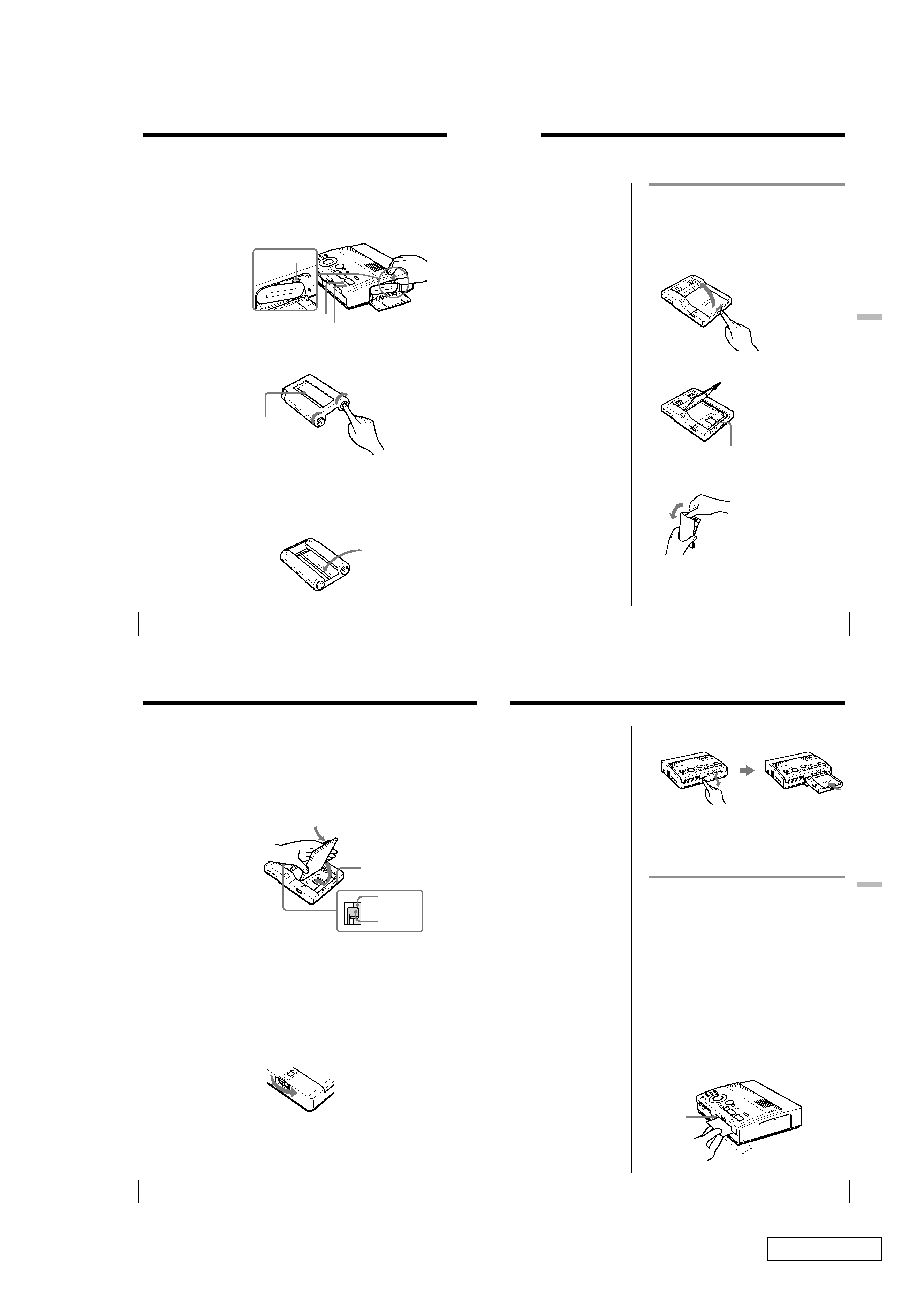
Insert the print cartridge into the printer.
Use only the print cartridge supplied with the print
paper packed in the same carton.
1 Press PUSH to open the cartridge compartment lid.
2 Wind up the ink ribbon to remove the slack.
3 Insert the print cartridge firmly until it clicks into
place and close the cartridge compartment lid.
If the print cartridge does not click into place
Remove the print cartridge, and then re-insert it.
Labeled side
Loading the print cartridge
Caution
Never put your hand into
the cartridge
compartment. The
thermal head reaches
high temperatures,
especially after repeated
printing.
Notes
· If the print cartridge is
not loaded when you
turn on the printer, the
warning sound beeps
and the ribbon error
indicator lights up.
· When installing the ink
ribbon cartridge, stand
it as illustrated so that
dust will not get on the
ink ribbon.
· Do not touch the ink
ribbon or place the
print cartridge in a
dusty location.
Fingerprints or dust on
the ink ribbon may
result in imperfect
printing.
Wind the ribbon
until the black
line comes to the
left edge.
While pressing the
center of the reel, wind
the ink ribbon in the
direction of the arrow.
continued
1-3
Confidential
DMP-1000P (AEP)
14GB
Setting Up
To replace the print cartridge
If the ribbon indicator flashes and the inserted paper
emerges after you insert the paper and the paper is
automatically loaded, remove the print paper and
replace the print cartridge.
Open the cartridge compartment lid and push up the
eject lever. Remove the used print cartridge and
replace it with a new one.
To load the half-used ink ribbon cartridge
If ink ribbon should tear
Repair the ribbon with transparent tape. There should
be no problem with using the remaining portion of the
ribbon. Before loading the ink ribbon cartridge into the
printer, turn the reel until the transparent tape can no
longer be seen.
Notes on storing the
print cartridge
· Avoid placing the
cartridge in a location
subject to:
high temperatures
high humidity
excessive dust
direct sunlight
· When you are going to
store a partially-used
cartridge for an
extended period of
time, store it in its
original bag.
Repair with
transparent tape.
Push up the eject lever,
then remove the used
print cartridge.
Eject lever
Wind the ribbon
until the black
line comes to the
left edge.
While pressing the
center of the reel, wind
the ink ribbon in the
direction of the arrow.
Ribbon error indicator
Paper supply indicator
Loading the print cartridge (continued)
15GB
Setting Up
Setting
Up
Inserting the print paper
Spacer
Inserting the print paper using the
supplied automatic feeder
By using the supplied automatic feeder, you can
supply the print paper automatically.
1 Open the lid of the paper tray by sliding the switch
on front to the right.
2 Make sure that the spacer is raised.
3 Riffle the print paper to avoid jamming the print
paper.
Make sure not to touch the printing surface (the
glossy side where nothing is printed).
Notes on using
automatic feeder
· If trouble occurs in
feeding the print paper,
the lamp on the printer
flashes. Remove the
feeder from the printer
and check that there is
no paper jammed in the
printer. When you
reinstall the feeder and
press the print button,
the printer prints the
set number of copies
again.
· The feeder can hold up
to 25 sheets of paper.
When you add paper to
a partially full feeder,
make sure that the total
number of sheets does
not exceed this limit. If
you do, the paper may
jam.
· Do not place different
types of paper in the
feeder. If you do, the
paper may jam.
· To insert paper after
the feeder is attached to
the printer, first remove
the feeder from the
printer and then insert
the paper into the
feeder.
· While printing, do not
open the feeder lid. If
you do, the paper may
jam.
16GB
Setting Up
4 Insert print paper with its printing surface (the side
where nothing is printed) facing up.
Make sure not to touch the printing surface and not
to bend the corners of the paper. You can load up
to 25 sheets of print paper or the print paper
designed for the printer into the feeder.
Make sure that the metal tabs on both sides fir over
the print paper.
5 Turn on the printer and press MEMORY or
CAPTURE to store an image for printing.
For the details, refer to "Printing" in the operating
instructions of the printer.
6 Turn the dial to set the number of copies to be
printed continuously.
You can set 1, 2, 3, 4, 5,10 or 25 copies. Turn the
dial until the desired number appears in the
window. Make sure it clicks at that time.
Otherwise, you may get the wrong number of
copies.
To print a number of
copies not specified on
the dial
Insert the desired number
of sheets and set the dial
to 25.
Inserting the print paper (continued)
Printing surface
Front
Paper
Metal tab
2
17GB
Setting Up
Setting
Up
7 Press "Push" on the cover of the automatic feeder,
then insert the feeder until it clicks.
8 Press the print button of the printer.
The print paper is automatically loaded into the
printer and printing starts.
Inserting the print paper manually
Insert the print paper sheet by sheet. This section
explains how to insert the standard type print paper.
Use the print paper designated for this printer only.
1 Turn on the power of the printer.
The POWER indicator lights up.
2 Follow printing procedures.
For details, see pages 20 to 39.
3 Insert the print paper straight with its blank
printing surface facing up, along the guide to the
left of the paper port.
Insert the paper until less than 2 cm (approx. 0.8
inches) remains. The paper is automatically loaded
when printing starts.
Guide
Less than 2 cm
To stop continuous
printing
Set the dial to 1. Printing
stops after the current
printing finishes.
If print paper runs out
during continuous
printing
Remove the feeder from
the printer. Then, insert
more print paper into the
feeder and reinstall the
feeder to the printer. The
printing resumes
automatically.
Notes on inserting the
print paper manually
· Insert the print paper
straight along the guide
to the left of the paper
port. If the paper is
positioned to the right
or slanted, the printing
area may get out of
position.
· The paper may not be
loaded automatically if
you do not insert the
paper firmly.