COMPACT DISC
COMPACT PLAYER
TECHNICAL THEORY
FOR SERVICING
DISCMAN
POWER SUPPLY CIRCUIT
OPERATION MANUAL
[photo: D-E705]

-- 2 --
Contents
1. POWER SUPPLY CIRCUIT CORRESPONDENCE TABLE ·················································································································· 3
2. OPERATION OF THE D-E705 SERIES POWER SUPPLY CIRCUIT ···································································································· 4
2-1. Types of Power Supply ········································································································································································ 4
2-2. Identifying the Power Supplies ··························································································································································· 4
2-3. Circuit Voltage ····················································································································································································· 5
2-4. Charging Circuit ·················································································································································································· 15
2-5. APC Circuit ························································································································································································· 19
2-6. ESP (Electronic Shock Protection) Circuit ········································································································································· 25
3. OPERATION OF THE D-365 SERIES POWER SUPPLY CIRCUIT ······································································································ 26
3-1. Types of Power Supply ········································································································································································ 26
3-2. Identifying the Power Supplies ··························································································································································· 26
3-3. Circuit Voltage ····················································································································································································· 27
3-4. Charging Circuit (Operation of the CHARGE MONITOR IC403) ···································································································· 35
4. OPERATION OF THE D-245 SERIES POWER SUPPLY CIRCUIT ······································································································ 36
4-1. Types of Power Supply ········································································································································································ 36
4-2. Identifying the Power Supplies ··························································································································································· 36
4-3. Circuit Voltage ····················································································································································································· 37
4-4. Charging Circuit ·················································································································································································· 47
5. APPENDIX: TYPES AND APPLICATIONS OF SECONDARY BATTERIES FOR PORTABLE EQUIPMENT
(RECHARGEABLE BATTERIES) ··························································································································································· 48
5-1. Nickel-Cadmium Rechargeable Battery ·············································································································································· 48
5-2. Nickel-Hydrogen Rechargeable Battery ·············································································································································· 55
5-3. Lithium-Ion Secondary Battery ··························································································································································· 59
-- 3 --
1. POWER SUPPLY CIRCUIT CORRESPONDENCE TABLE
Table 1-1 shows the power supply circuit correspondence table. This new technical theory for servicing shows the power supply block
diagrams of the following models among the respective power supply circuit series.
· D-E705 series power supply system
n D-E705
· D-365 series power supply system
n D-365
· D-245 series power supply system
n D-245
However, among the D-245 series models, those that do not have the ESP circuit do not have the D-RAM IC drive voltage generator
circuit which is described here in chapter "4. OPERATION OF THE D-245 SERIES POWER SUPPLY CIRCUIT."
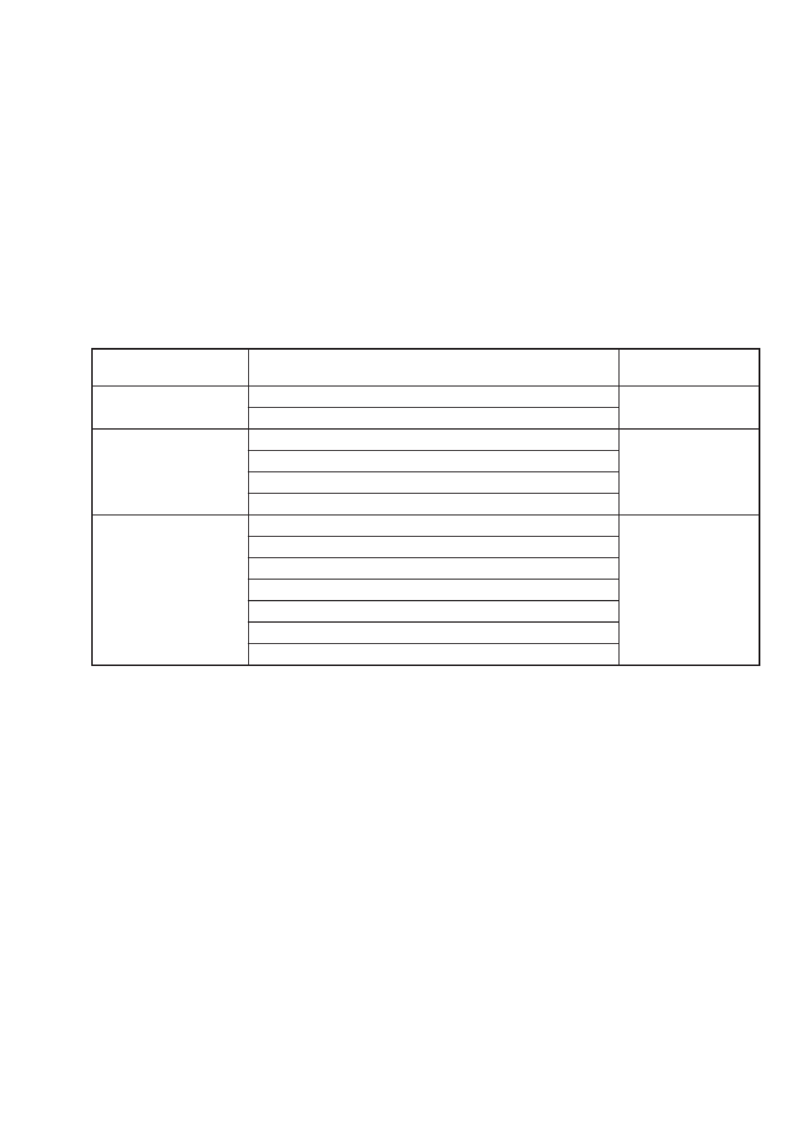
Table 1-1 Power supply circuit correspondence table
Power supply circuit series
D-E705 series
D-365 series
D-245 series
Model names
D-E700/E800
D-E705/E805
D-263/265
D-365/375/368/369CK
D-465/475
D-E500/E504
D-140/141/143/141CK/142CK/144K/145/147CR/148CR
D-150AN/151/151C/151V/152CK/152CKT/153/155
D-162CKC/162CKT
D-240/247/242CK/242SK/242CKT/243CK/245
D-330/340/345
D-451SP
D-835K/837K/838K/840K/842K/844K/848K
Reference pages
pages 3 to 25
pages 26 to 35
pages 36 to 47
-- 4 --
2. OPERATION OF THE D-E705 SERIES POWER SUPPLY CIRCUIT
2-1. Types of Power Supply
The D-E705 series compact CD player can be operated on the following three types of power supply.
DC power supply
· AC adapter .............................................................................. 4.5 V (supplied)
Battery
· Dry cell battery (size AA, 2 pcs) .............................................. 3.0 V (optional), or
· Rechargeable nickel-hydrogen battery (NH-DM2AA) ........... 2.4 V (supplied)
2-2. Identifying the Power Supplies
When the system controller IC801 is started up, it identifies from where the main power voltage is supplied. It also stops operation
if batteries that do not satisfy the specifications are used. The system controller IC identifies the power supplies from the following
three detections.
(1) Pin %¶[DCINMNT] : The voltage that is obtained by dividing the DCIN input voltage by the resistors.
(2) Pin %·[BATMNT]
: The voltage that is obtained by dividing the battery terminal voltage by the resistors.
(3) Pin ^¡[CHGMNT2] : The voltage from the rechargeable battery detection terminal
("H": When the supplied rechargeable battery is inserted)
* 2-1: When a rechargeable battery is inserted, the input of Pin ^¡[CHGMNT2] goes high.
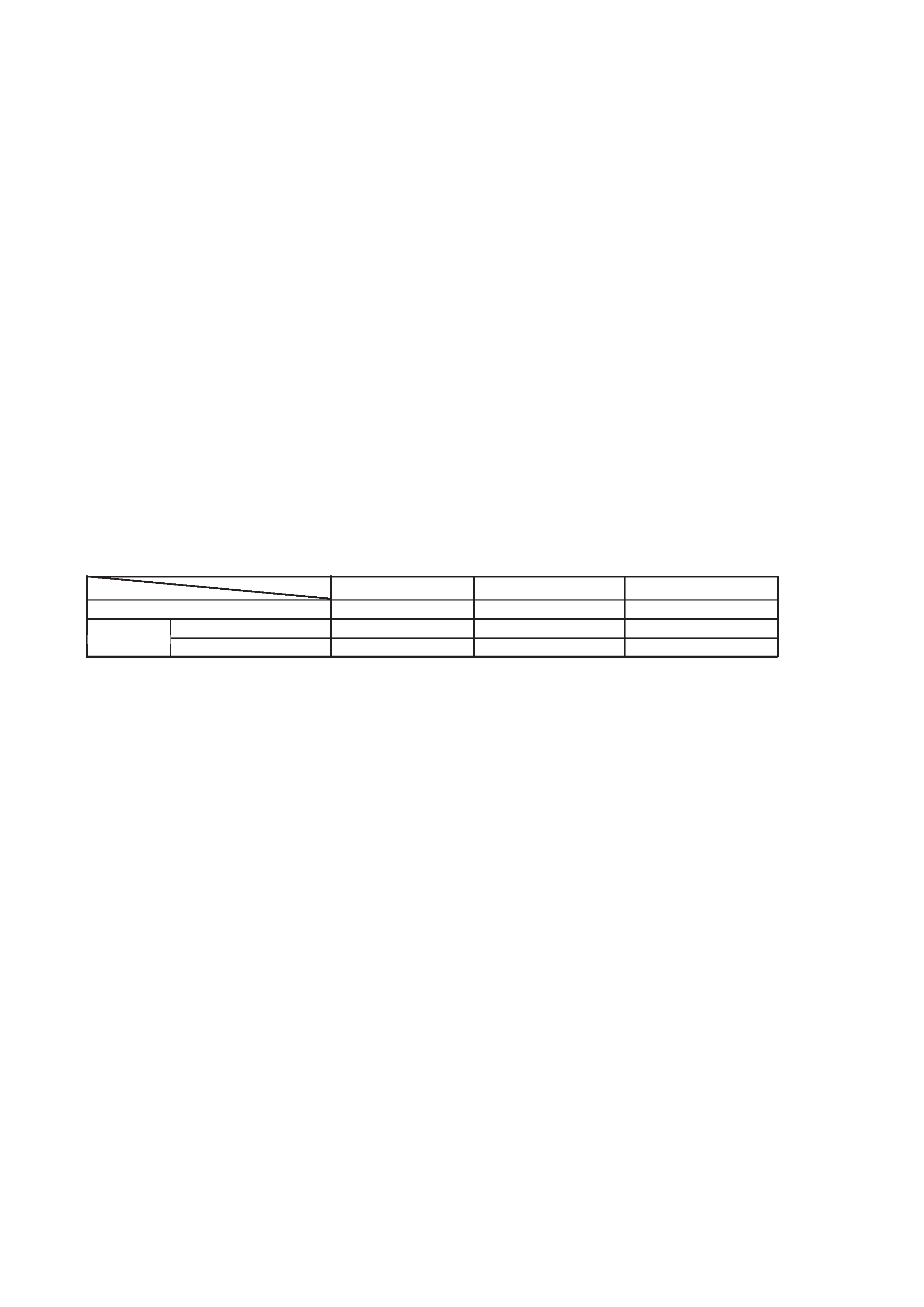
Table 2-1 Power supply identification table
DC supply (from AC adapter)
Battery
Rechargeable battery
Dry cell battery
Pin %¶[DCINMNT]
H
L
L
Pin %·[BATMNT]
H
H
H
Pin ^¡[CHGMNT2]
L (H*2-1)
H
L
-- 5 --
2-3. Circuit Voltage
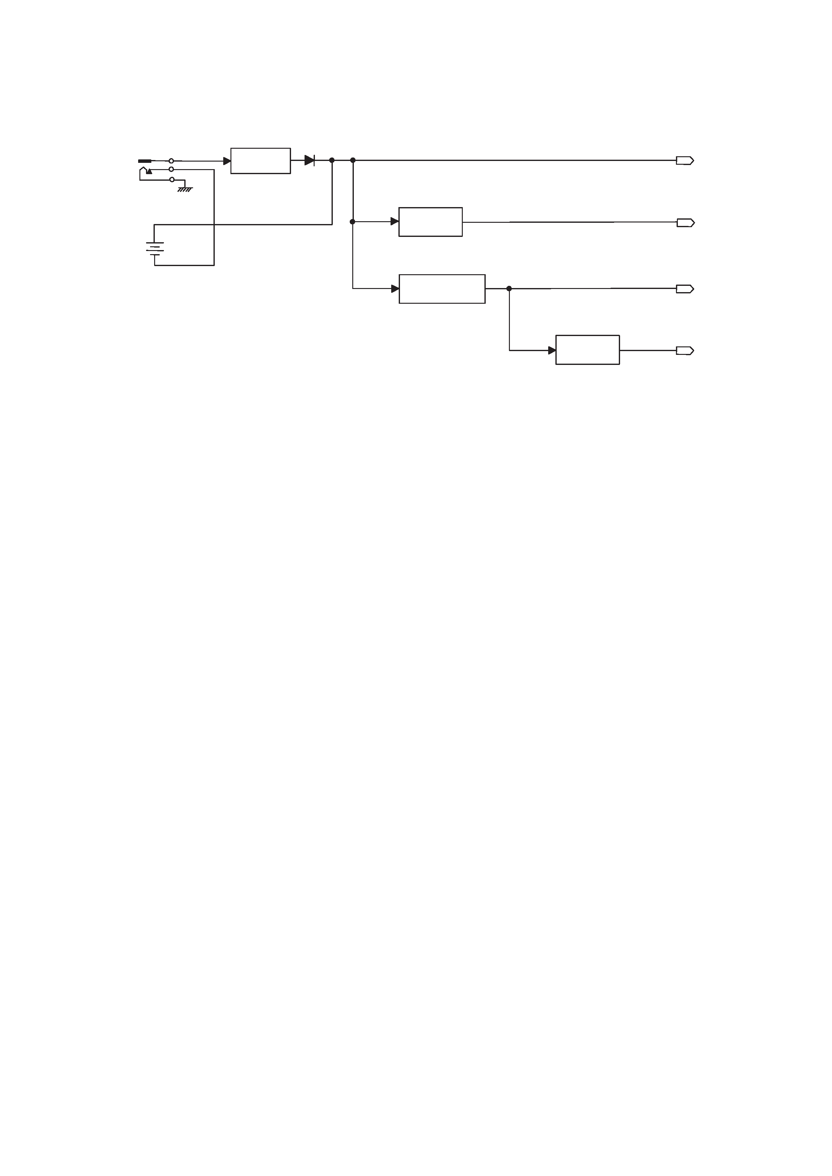
Fig. 2-1 Power supply voltage generation block diagram
During AC adaptor drive operation, the following four outputs of the power supply voltage are generated. (Refer to Fig. 2-1.)
1 VIN voltage
· The external voltage input to the DC jack is regulated by the SERIES REGULATOR (Q414, Q402), passed through D407 and output
as the VIN voltage (approx. 4.5 V).
· When the Discman is operated on battery, the battery terminal voltage is supplied as the VIN voltage.
2 VCPU voltage n "POWER CONTROL IC401"
· This voltage is used for driving the system controller IC801, and is 3.0 V.
3 VCC voltage n "2.75 V DC-DC CONVERTER (POWER CONTROL IC401, T401, Q403, Q405, etc.)"
· This voltage is used by the RF AMP IC501, DIGITAL SIGNAL PROCESSOR IC502, COIL/MOTOR DRIVE IC504, etc., and is 2.75 V.
4 VG voltage n "COIL/MOTOR DRIVE IC504"
· This voltage is used by the POWER CONTROL IC401, etc., and is approx. 12 V.
Generation of the respective voltages is described below.
1. Generation of VIN Voltage
When the DC plug of the AC adapter is connected to the DC jack, the input voltage is regulated by the SERIES REGULATOR (Q414 and
Q402), passed through D407 and is output to the POWER CONTROL IC401 and others as the VIN voltage.
3[V]
REGULATOR
DCIN
IC401
POWER CONTROL
2.75[V]
DC-DC CONVERTER
IC401,T401,Q403,Q405
12[V]
REGULATOR
IC504
COIL/MOTOR DRIVE
1 VIN VOLTAGE
2 VCPU VOLTAGE
3 VCC VOLTAGE
4 VG VOLTAGE
12[V]
2.75[V]
3[V]
DC VOLTAGE
or
BATTERY VOLTAGE
BATTERY
SERIES
REGULATOR
Q414,Q402
D407