MICROFILM
SERVICE MANUAL
COMPACT DISC COMPACT PLAYER
US Model
D-E561/E565
CD player section
System
Compact disc digital audio system
Laser diode properties
Material: GaAlAs
Wavelength:
=780 nm
Emission duration: Continuous
Laser output: Less than 44.6 µW (This output
is the value measured at a distance of 200
mm from the objective lens surface on the
optical pick-up block with 7 mm aperture.)
Error correction
Sony Super Strategy Cross Interleave Reed
Solomon Code
D-A conversion
1-bit quartz time-axis control
Frequency response
20 20,000 Hz +1
2 dB (measured by EIAJ CP-
307)
Output (at 4.5 V input level)
Headphones (stereo minijack)
Approx. 15 mW + approx. 15 mW
at 16 ohms
Line output (stereo minijack)
Output level 0.7 V rms at 47 kilohms
Recommended load impedance over 10
kilohms
Optical digital output (optical output
connector)
Output level: 21 to 15 dBm
Wavelength: 630 690 nm at peak level
General
Power requirements
For the area code of the model you purchased,
check the upper left side of the bar code on the
package.
· Two Sony NH-DM2AA rechargeable
batteries: 2.4 V DC
Two Sony NC-DMAA rechargeable
batteries: 2.4 V DC
· Two LR6 (size AA) batteries: 3 V DC
· AC power adaptor (DC IN 4.5 V jack):
120 V, 60 Hz
· Sony DCC-E245 car battery cord for use on
car battery: 4.5 V DC
Dimensions (w/h/d) (without projecting
parts and controls)
Approx. 131.8
× 23.9 × 142.0 mm
(5 1/4
× 31/32 × 5 5/8 in.)
Mass (without rechargeable batteries)
Approx. 200 g (7.0 oz)
Operating temperature
5 °C 35 °C (41 °F 95 °F)
SPECIFICATIONS
Model Name Using Similar Mechanism
D-E551
CD Mechanism Type
CDM-2911EBA
Optical Pick-Up Name
DAX-11E
Supplied accessories
For the area code of the model you purchased,
check the upper left side of the bar code on the
package.
D-E561
AC power adaptor (1)
Headphones (1)
D-E565
AC power adaptor (1)
Headphones with remote control (1)
Rechargeable batteries (2)
Battery carrying case (1)
Design and specifications are subject to change
without notice.

2
TABLE OF CONTENTS
1.
SERVICING NOTES ............................................... 3
2.
GENERAL ................................................................... 4
3.
DISASSEMBLY ......................................................... 7
4.
SERVICE MODE ...................................................... 8
5.
ELECTRICAL ADJUSTMENTS ......................... 9
6.
DIAGRAMS
6-1. Block Diagram MAIN Section ................................. 13
6-2. Block Diagram POWER SUPPLY Section .............. 17
6-3. IC Pin Function Description ........................................... 19
6-4. Printed Wiring Board ...................................................... 22
6-5. Schematic Diagram ......................................................... 25
7.
EXPLODED VIEWS ................................................ 34
8.
ELECTRICAL PARTS LIST ............................... 37
CAUTION
Use of controls or adjustments or performance of procedures
other than those specified herein may result in hazardous ra-
diation exposure.
Flexible Circuit Board Repairing
· Keep the temperature of the soldering iron around 270 °C dur-
ing repairing.
· Do not touch the soldering iron on the same conductor of the
circuit board (within 3 times).
· Be careful not to apply force on the conductor when soldering
or unsoldering.
Notes on chip component replacement
· Never reuse a disconnected chip component.
· Notice that the minus side of a tantalum capacitor may be dam-
aged by heat.
SAFETY-RELATED COMPONENT WARNING!!
COMPONENTS IDENTIFIED BY MARK
! OR DOTTED
LINE WITH MARK
! ON THE SCHEMATIC DIAGRAMS
AND IN THE PARTS LIST ARE CRITICAL TO SAFE
OPERATION. REPLACE THESE COMPONENTS WITH
SONY PARTS WHOSE PART NUMBERS APPEAR AS
SHOWN IN THIS MANUAL OR IN SUPPLEMENTS PUB-
LISHED BY SONY.
3
SECTION 1
SERVICING NOTES
NOTES ON HANDLING THE OPTICAL PICK-UP
BLOCK OR BASE UNIT
The laser diode in the optical pick-up block may suffer electro-
static breakdown because of the potential difference generated by
the charged electrostatic load, etc. on clothing and the human body.
During repair, pay attention to electrostatic breakdown and also
use the procedure in the printed matter which is included in the
repair parts.
The flexible board is easily damaged and should be handled with
care.
Before Replacing the Optical Pick-Up Block
Please be sure to check thoroughly the parameters as par the "Op-
tical Pick-Up Block Checking Procedures" (Part No.: 9-960-027-
11) issued separately before replacing the optical pick-up block.
Note and specifications required to check are given below.
· FOK output: IC501 !TM pin
When checking FOK, remove the lead wire to disc motor.
· S curve P-to-P value: 0.6 to 1.8 Vp-p IC501 #¡ pin
When checking S curve P-to-P value, remove the lead wire to
disc motor.
· RF signal P-to-P value: 0.8 to 1.2 Vp-p
· Traverse signal P-to-P value: 1.2 Vp-p
· The repairing grating holder is impossible.
Precautions for Checking Emission of Laser Diode
Laser light of the equipment is focused by the object lens in the
optical pick-up so that the light focuses on the reflection surface
of the disc. Therefore, be sure to keep your eyes more then 30 cm
apart from the object lens when you check the emission of laser
diode.
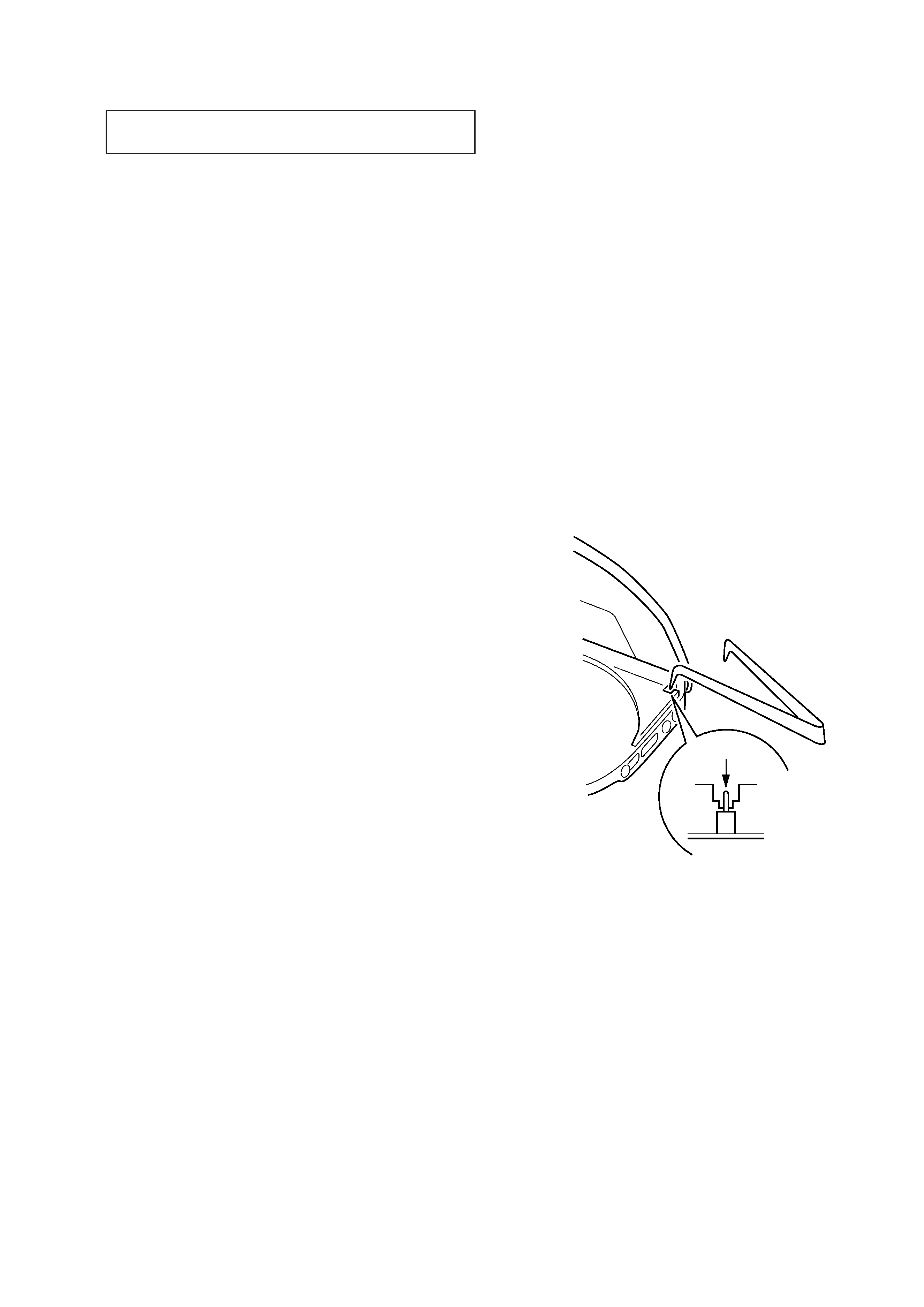
Laser Diode Checking Methods
During normal operation of the equipment, emission of the laser
diode is prohibited unless the upper panel is closed while turning
ON the S801. (push switch type)
The following two checking methods for the laser diode are oper-
able.
· Method (In the service mode or normal operation):
Emission of the laser diode is visually checked.
1. Open the upper lid.
2. Push the S801 as shown in Fig. 1.
3. Press the
^ key.
4. Check the object lens for confirming normal emission of the
laser diode. If not emitting, there is a trouble in the automatic
power control circuit or the optical pick-up.
During normal operation, the laser diode is turned ON about
2.5 seconds for focus searching.
Fig. 1 Method to push the S801
S801
4
SECTION 2
GENERAL
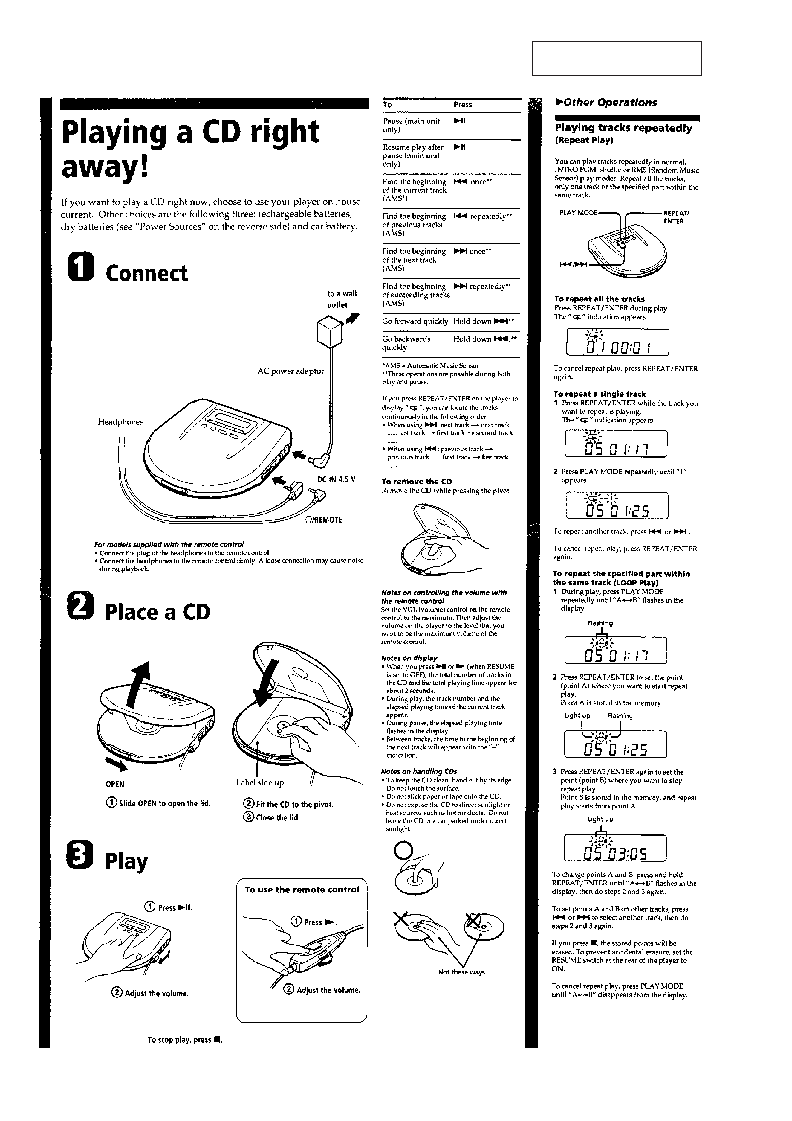
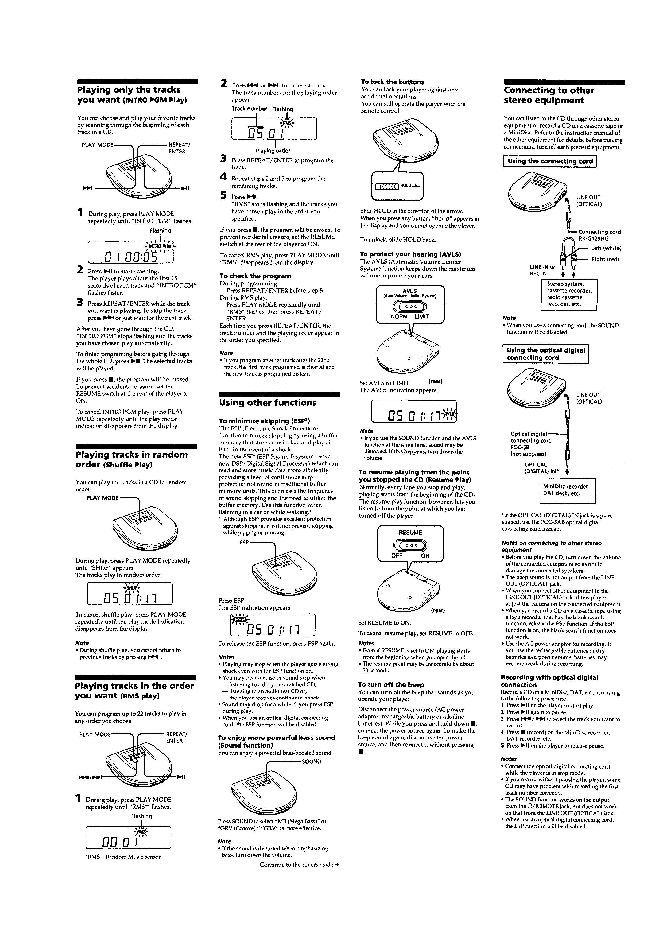
This section is extracted from
instruction manual.
5