-- 1 --
D825TM
SPECIFICATIONS
D-1
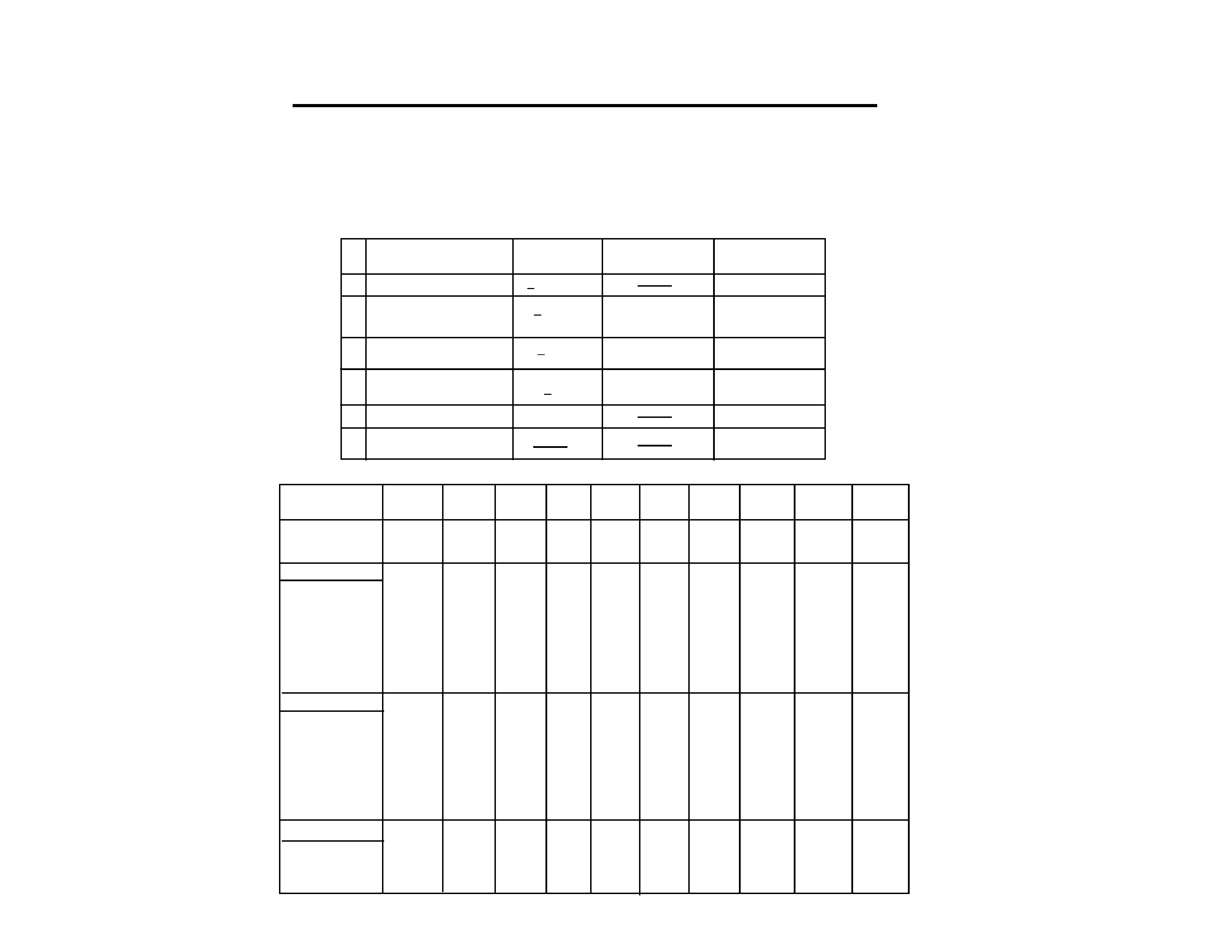
Picture tube
Video image area
Logical resolution
Physical resolution
Standard image area
Input signal
Video
Sync
0.25 mm aperture grill pitch
15 inches measured diagonally
90-degree deflection
(14" maximum viewing image)
Approx. 286.5 x 214 mm (w/h)
(113/8 x 81/2 inches)
Horizontal: Max. 1280 dots
Vertical: Max. 1024 lines
Horizontal: Max. 1024 dots
Vertical: Max. 768 lines
Approx. 270 x 202 mm (w/h)
(103/4 x 8 inches)
Analog RGB (75 ohms typical)
0.7 Vp-p, Positive
External HD/VD, Composite
Polarity Free TTL
Video Composite (Sync on Green)
0.3 Vp-p, Negative
Power Consumption
Maximum
Nominal
Deflection frequency
AC input voltage / current
Dimensions
Mass
CHASSIS
110W
80W, 273 BTU/h
Horizontal: 30 to 70 KHz
Vertical: 50 to120 Hz
100 to 120 V, 50/60 Hz, 1.8 A
220 to 240V, 50/60Hz, 1A
368 x 392 x 384.5 mm (w/h/d)
(141/2 x 151/2 x 151/4 inches)
Approx. 14.0 kg (30 lb 14 oz)
SERVICE MANUAL
Design and specifications are subject to change without notice.
D825TM
COLOR MONITOR
D825TM
US Model
Canadian Model
Japan Model
AEP Model
S. Hemisphere Model
Chassis No. SCC-L06C-A
R
-- 2 --
D825TM
State
Power
Required
u Power indicator
consumption
recovery time
POWER SAVING FUNCTION
This monitor has three Power Saving modes.
By sensing the absence of a video signal from the
computer, it reduces power consumption as follows:
NOTE:
TIMING SPECIFICATION
MODE
1
2
3
4
5
6
7
8
9
10
Resolution (H x V)
640X480
720X400
640X480
640X480
800X600
800X600
800X600
1024X768
1024X768
1280X1024
Dot Clock (MHz)
25.175
28.321
31.500
36.000
40.000
49.500
56.250
78.750
94.500
108.000
HORIZONTAL
Hor. Freq. (kHz)
31.469
31.468
37.500
43.269
37.879
46.875
53.674
60.023
68.677
63.981
H-Total
31.778
31.779
26.667
23.111
26.400
21.333
18.631
16.660
14.561
15.630
H-Blanking
6.356
6.356
6.349
5.333
6.400
5.172
4.409
3.657
3.725
3.778
H-Front Porch
0.636
0.636
0.508
1.556
1.000
0.323
0.569
0.203
0.508
0.444
H-Sync.
3.813
3.178
2.032
1.556
3.200
1.616
1.138
1.219
1.016
1.037
H-Back Porch
1.907
2.542
3.810
2.222
2.200
3.232
2.702
2.235
2.201
2.296
H-Active
25.422
25.423
20.317
17.778
20.000
16.162
14.222
13.003
10.836
11.852
(
µsec)
VERTICAL
Ver. Freq. (Hz)
59.940
70.084
75.000
85.008
60.317
75.000
85.061
75.029
84.997
60.020
V-Total
525
449
500
509
628
625
631
800
808
1066
V-Blanking
45
49
20
29
28
25
31
32
40
42
V-Front Porch
10
13
1
1
1
1
1
1
1
1
V-Sync.
2
2
3
3
4
3
3
3
3
3
V-Back Porch
33
34
16
25
23
21
27
28
36
38
V-Active
480
400
480
480
600
600
600
768
768
1024
(lines)
SYNC.
Int(G)
NO
NO
NO
NO
NO
NO
NO
NO
NO
NO
Ext (H/V)/Polarity
YES -/-
YES -/+
YES -/-
YES -/-
YES +/+
YES +/+
YES +/+
YES +/+
YES +/+
YES +/+
Ext (CS)/Polarity
NO
NO
NO
NO
NO
NO
NO
NO
NO
NO
Int / Non Int
Non Int
Non Int
Non Int
Non Int
Non Int
Non Int
Non Int
Non Int
Non Int
Non Int
1.
Normal Operation
< 110W
Green on
2.
Standby (1st mode)
< 15W
approx. 3 sec.
Green and orange
alternate
3.
Suspend (2nd mode)
<15W
Approx. 3 sec.
Green and orange
alternate
4.
Active-off (3rd mode)
<8W
Approx. 10 sec.
Orange
5.
Power-off
0W
Off
6.
Failure mode
Orange flashing
If no video signal is input to the monitor, the
"NO INPUT SIGNAL" message appears. After
about 30 seconds, the Power Saving function
automatically puts the monitor into active-off
mode and the indicator lights up orange. Once
the monitor detects horizontal and vertical sync
signals, the monitor automatically resumes
normal operation mode.
-- 3 --
D825TM
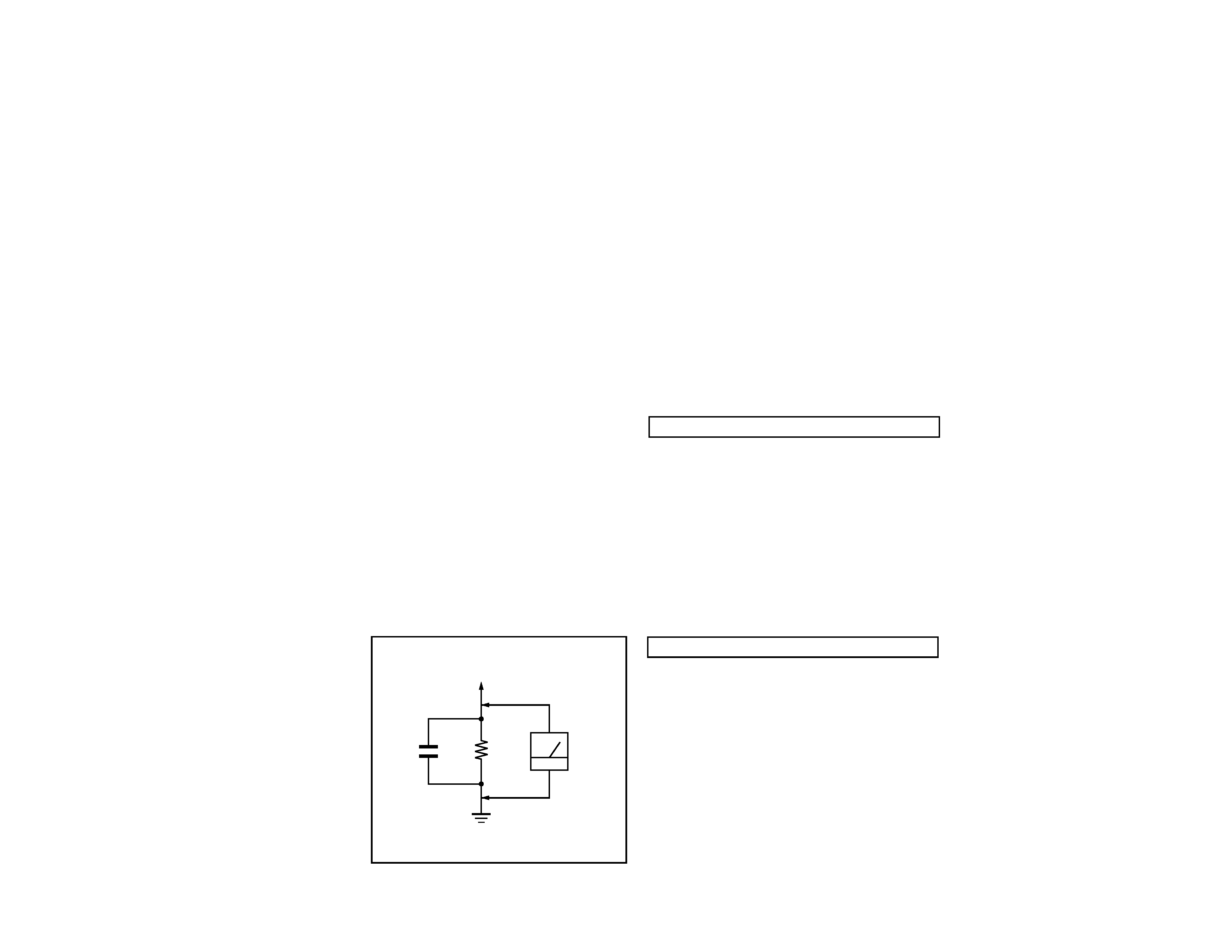
1.5 k
0.15 µF
AC
Voltmeter
(0.75 V)
To Exposed Metal
Parts on Set
Earth Ground
SAFETY CHECK-OUT
(US Model only)
After correcting the original service problem, perform
the following safety checks before releasing the set to the
customer:
LEAKAGE TEST
The AC leakage from any exposed metal part to earth ground
and from all exposed metal parts to any exposed metal part having
a return to chassis, must not exceed 0.5 mA (500 microampere).
Leakage current can be measured by any one of three methods.
WARNING!!
WARNING!!
WARNING!!
WARNING!!
WARNING!!
NEVER TURN ON THE POWER IN A CONDITION IN WHICH THE
DEGAUSS COIL HAS BEEN REMOVED.
SAFETY-RELATED COMPONENT WARNING!!
COMPONENTS IDENTIFIED BY SHADING AND MARK
¡ ON
THE SCHEMATIC DIAGRAMS, EXPLODED VIEWS AND IN THE
PARTS LIST ARE CRITICAL FOR SAFE OPERATION. REPLACE
THESE COMPONENTS WITH SONY PARTS WHOSE PART
NUMBERS APPEAR AS SHOWN IN THIS MANUAL OR IN
SUPPLEMENTS PUBLISHED BY SONY. CIRCUIT ADJUSTMENTS
THAT ARE CRITICAL FOR SAFE OPERATION ARE IDENTIFIED
IN THIS MANUAL. FOLLOW THESE PROCEDURES WHENEVER
CRITICAL COMPONENTS ARE REPLACED OR IMPROPER
OPERATION IS SUSPECTED.
AVERTISSEMENT!!
NE JAMAIS METTRE SOUS TENSION QUAND LA BOBINE DE
DEMAGNETISATION EST ENLEVEE.
ATTENTION AUX COMPOSANTS RELATIFS A LA
SECURITE!!
LES COMPOSANTS IDENTIFIES PAR UNE TRAME ET PAR UNE
MARQUE
¡ SUR LES SCHEMAS DE PRINCIPE, LES VUES
EXPLOSEES ET LES LISTES DE PIECES SONT D'UNE
IMPORTANCE
CRITIQUE
POUR
LA
SECURITE
DU
FONCTIONNEMENT. NE LES REMPLACER QUE PAR DES
COMPOSANTS SONY DONT LE NUMERO DE PIECE EST
INDIQUE DANS LE PRESENT MANUEL OU DANS DES SUPPLE-
MENTS PUBLIES PAR SONY. LES REGLAGES DE CIRCUIT
DONT
L'IMPORTANCE
EST
CRITIQUE
POUR
LA
SECURITE DU FONCTIONNEMENT SONT IDENTIFIES DANS
LE PRESENT MANUEL. SUIVRE CES PROCEDURES LORS DE
CHAQUE REMPLACEMENT DE COMPOSANTS CRITIQUES, OU
LORSQU'UN MAUVAIS FONTIONNEMENT SUSPECTE.
1. Check the area of your repair for unsoldered or
poorly-soldered connections. Check the entire board
surface
for
solder
splashes
and
bridges.
2. Check the interboard wiring to ensure that no wires
are "pinched" or contact high-wattage resistors.
3. Check that all control knobs, shields, covers, ground
straps, and mounting hardware have been replaced.
Be absolutely certain that you have replaced all the
insulators.
4. Look for unauthorized replacement parts,
particularly transistors, that were installed during
a previous repair. Point them out to the customer
and recommend their replacement.
5. Look for parts which, though functioning, show
obvious signs of deterioration. Point them out to
the customer and recommend their replacement.
6. Check the line cords for cracks and abrasion.
Recommend the replacement of any such line cord
to the customer.
7. Check the B+ and HV to see if they are specified
values. Make sure your instruments are accurate;
be suspicious of your HV meter if sets always have
low HV.
8. Check the antenna terminals, metal trim,
"metallized" knobs, screws, and all other exposed
metal parts for AC Leakage. Check leakage as
described below.
1. A commercial leakage tester, such as the Simpson 229 or
RCA WT-540A. Follow the manufacturers' instructions to
use these instructions.
2. A battery-operated AC milliammeter. The Data Precision
245 digital multimeter is suitable for this job.
3. Measuring the voltage drop across a resistor by means of
a VOM or battery-operated AC voltmeter. The "limit"
indication is 0.75 V, so analog meters must have an accurate
low voltage scale. The Simpson's 250 and Sanwa
SH-63Trd are examples of passive VOMs that are suitable.
Nearly all battery operated digital multimeters that have a
2V AC range are suitable. (See Fig. A)

-- 4 --
D825TM
TABLE OF CONTENTS
Section
Title
Page
1. GENERAL ................................................................................... 5
2. DISASSEMBLY
2-1. Cabinet Removal ............................................................10
2-2. Service Position .............................................................. 10
2-3. D,A and D1 Board Removal.......................................... 10
2-4. Picture Tube Removal ................................................... 11
3. SAFETY RELATED ADJUSTMENT................................. 12
4. ADJUSTMENTS ........................................................................ 13
5. DIAGRAMS
5-1. Block Diagram ................................................................15
5-2. Circuit Boards Location ................................................. 18
5-3. Schematic Diagrams and Printed Wiring Boards ...... 18
1. D Board - Schematic Diagram ................................. 19
2. A Board - Schematic Diagram ................................. 23
3. D1 Board - Schematic Diagram .............................. 26
5-4. Semiconductors ..............................................................27
6. EXPLODED VIEWS
6-1. Chassis (US, CND) .........................................................29
6-2. Chassis (Japan, S. Hemisphere, AEP)........................ 30
6-3. Packing Materials .......................................................... 31
7. ELECTRICAL PARTS LIST ................................................ 32
--
5
--
D825TM
SECTION 1
GENERAL
The instructions given here are partial abstracts from the Operating Instruction
Manual. The page numbers shown reflect those of the Operating Instruction Manual.
4
Table of Contents
Installation
· Prevent internal heat build up by allowing adequate air
circulation. Do not place the monitor on surfaces (rugs,
blankets, etc.) or near materials (curtains, draperies) that
may block the ventilation holes.
· Do not install the monitor near heat sources such as
radiators or air ducts, or in a place subject to direct
sunlight, excessive dust, mechanical vibration or shock.
· Do not place the monitor near equipment that generates
magnetism, such as a converter, or high voltage power
lines.
Maintenance
· Clean the cabinet, panel and controls with a soft cloth
lightly moistened with a mild detergent solution. Do not
use any type of abrasive pad, scouring powder or solvent
such as alcohol or benzine.
· Do not rub, touch or tap the surface of the screen with
sharp or abrasive items such as a ball point pen or
screwdriver. This type of contact may scratch the picture
tube.
Warning on Power Connection
· Use an appropriate power cord for your local power
supply.
For customers in the U.S.A.
If you do not use an appropriate power cord, the monitor
will not conform to mandatory FCC standards.
for 220 to 240 V AC
for 100 to 120 V AC
· Before disconnecting the power cord, wait for at least 30
seconds after turning off the power to allow the static
electricity on the CRT display surface to discharge.
· After the power has been turned on, the CRT is
demagnetized (degaussed) for about 5 seconds. This
generates a strong magnetic field around the metal frame,
which may affect the data stored on magnetic tapes and
disks near the monitor. Place magnetic recording
equipment, tapes and disks away from this monitor.
Read First! ................................................................................. 3
Damper Wire ............................................................................ 3
Setup .......................................................................................... 3
Quick Specifications ................................................................ 3
Precautions ............................................................................... 4
Plug and Play ........................................................................... 4
Parts and Controls ................................................................... 5
The OSD (On-screen Display) System ................................. 6
Resetting the Adjustments ..................................................... 9
Plug and Play
This monitor complies with the DDCTM1 and DDC2B Display
Data Channel (DDC) standards of VESA.
When a DDC1 host system is connected, the monitor
synchronizes with the V. CLK in accordance with the VESA
standards, and outputs the EDID (Extended Display
Identification Data) to the data line.
When a DDC2B host system is connected, the monitor
automatically switches to the appropriate standard.
DDCTM is a trademark of Video Electronics Standard
Association.
· Your monitor operates according to DDC2B. Only
computers that support the same guidelines and operate
at the same or higher level can make use of this feature.
· If your computer does not support the relevant
guidelines, you can still use your monitor and computer.
You may need to manually specify the appropriate
resolution in the computer.
· The highest resolution automatically selected may not
give the best result. You may need to manually select the
most suitable resolution in the computer.
Precautions
Examples of plug types:
for 240 V AC only
The socket should be installed near the equipment and
be easily accessible.
Graphic Enhancement Mode (GEM) .................................. 10
Specifications .......................................................................... 10
Monitor Information ............................................................. 11
Power Saving Function and LED Indicators .................... 11
Preset and User Modes ......................................................... 11
Warning Messages ................................................................. 12
Troubleshooting ..................................................................... 12
Dell Computer Corporation's Environmental Program . 14
Appendix .............................................................................. 109
Getting Started
5
Getting Started
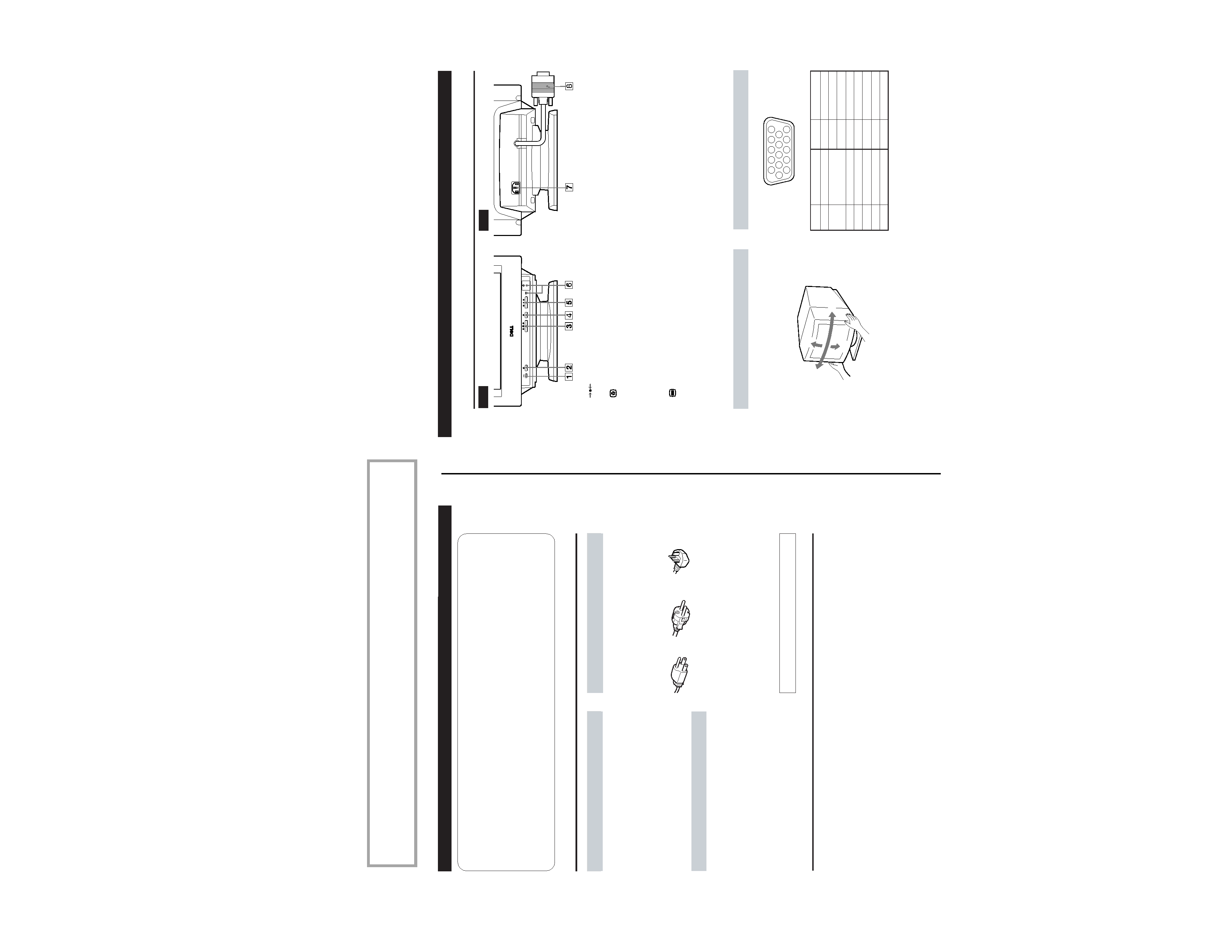
Video Connector
Pin No. Signal
1
Red
2
Green (Composite
Sync on Green)
3
Blue
4
Ground
5
CPU Sense
6
Red Ground
7
Green Ground
Pin No.
Signal
8
Blue Ground
9
Not used (no pin)
10
Ground
11
Ground
12
SDA (serial data)
13
Horizontal Sync
14
Vertical Sync
15
SCL (serial clock)
Use of the Tilt/Swivel
With the tilt/swivel, you can adjust this monitor to any desired
angle within 180° horizontally and 20° vertically.
To turn the monitor vertically and horizontally, hold it at the
bottom with both hands as shown below.
Parts and Controls
Rear
1
(RESET) button (pages 6 and 9)
Resets the adjustments to the factory settings.
2
(GEM) button (page 10)
Selects the Graphic Enhancement Mode.
3 ¨ (BRIGHTNESS) ./> buttons (page 6)
Adjust the picture brightness.
Operate as the ./> buttons when adjusting other
items.
4
(MENU) button (pages 6 and 11)
Displays the MENU OSD.
5 > (CONTRAST) ?// buttons (page 6)
Adjust the contrast.
Operate as the ?// buttons when adjusting other
items.
6 u (POWER) switch and indicator (page 11)
Turns the monitor on and off.
The indicator lights up green when the monitor is on,
and lights up orange when the monitor is in Power
Saving mode.
7 AC IN connector
Provides AC power to the monitor.
8 Video input connector (HD15)
Inputs RGB video signals and SYNC signals
Front
Getting Started
15
°
90
°
90
°
5
°
6
11 12 13 14 15
12
3
4
5
78
9 10