SERVICE MANUAL
CHASSIS
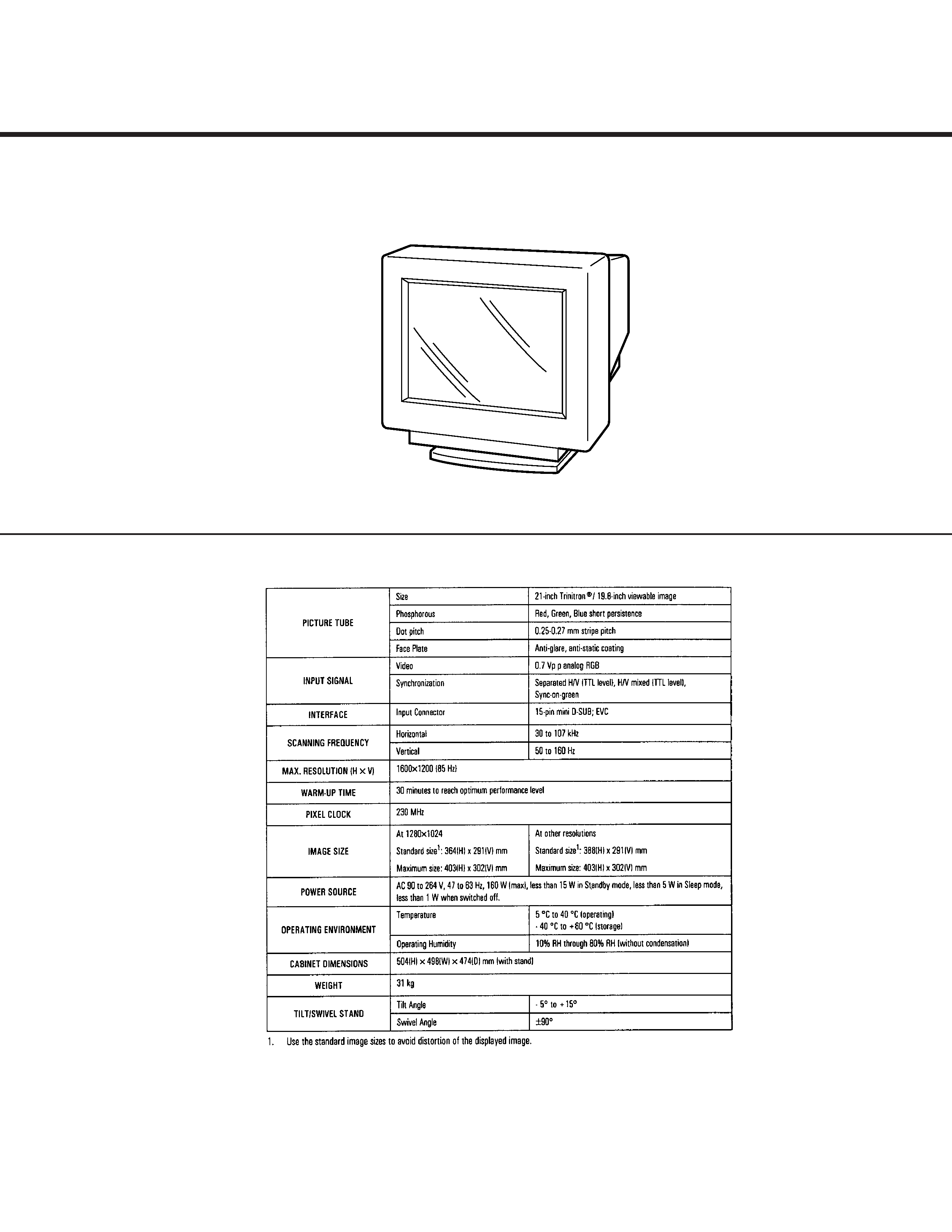
SPECIFICATIONS
N3
D2846
US Model
Canadian Model
AEP Model
Chassis No. SCC-L04G-A
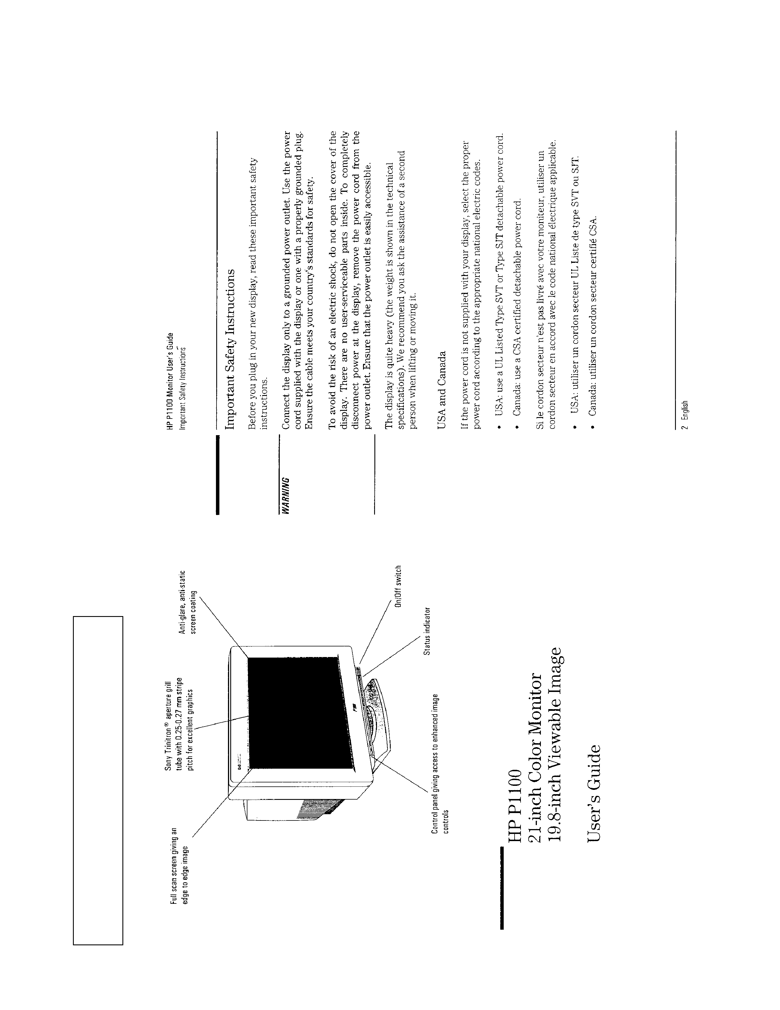
HP
COLOR GRAPHIC DISPLAY
2
D2846
SAFETY CHECK-OUT
(US Model only)
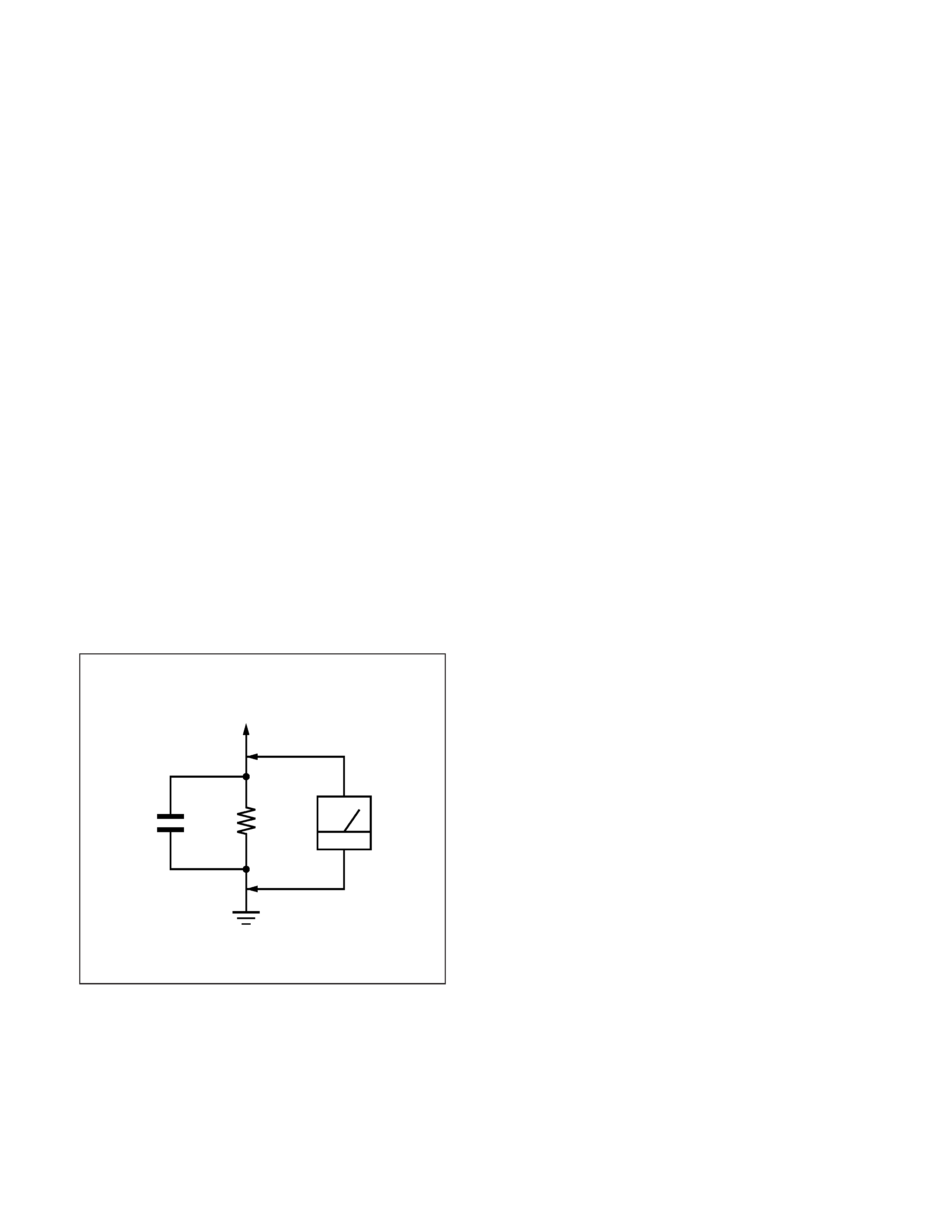
LEAKAGE TEST
The AC leakage from any exposed metal part to earth ground
and from all exposed metal parts to any exposed metal part
having a return to chassis, must not exceed 0.5 mA (500
microampers).
Leakage current can be measured by any one of three meth-
ods.
1. A commercial leakage tester, such as the Simpson 229 or
RCA WT-540A. Follow the manufacturers' instructions to
use these instruments.
2. A battery-operated AC milliammeter. The Data Precision 245
digital multimeter is suitable for this job.
3. Measuring the voltage drop across a resistor by means of a
VOM or battery-operated AC voltmeter. The "limit" indica-
tion is 0.75 V, so analog meters must have an accurate low-
voltage scale. The Simpson 250 and Sanwa SH-63Trd are ex-
amples of a passive VOMs that are suitable. Nearly all battery
operated digital multimeters that have a 2 V AC range are suit-
able. (See Fig. A)
WARNING!!
NEVER TURN ON THE POWER IN A CONDITION IN
WHICH THE DEGAUSS COIL HAS BEEN REMOVED.
SAFETY-RELATED COMPONENT WARNING!!
COMPONENTS IDENTIFIED BY SHADING AND MARK
¡ ON THE SCHEMATIC DIAGRAMS, EXPLODED
VIEWS AND IN THE PARTS LIST ARE CRITICAL FOR
SAFE OPERATION. REPLACE THESE COMPONENTS
WITH SONY PARTS WHOSE PART NUMBERS AP-
PEAR AS SHOWN IN THIS MANUAL OR IN SUPPLE-
MENTS PUBLISHED BY SONY. CIRCUIT ADJUST-
MENTS THAT ARE CRITICAL FOR SAFE OPERATION
ARE IDENTIFIED IN THIS MANUAL. FOLLOW THESE
PROCEDURES WHENEVER CRITICAL COMPO-
NENTS ARE REPLACED OR IMPROPER OPERATION
IS SUSPECTED.
AVERTISSEMENT!!
NE JAMAIS METTRE SOUS TENSION QUAND LA
BOBINE DE DEMAGNETISATION EST ENLEVÉE.
ATTENTION AUX COMPOSANTS RELATIFS À LA
SÉCURITÉ!!
LES COMPOSANTS IDENTIFIÉS PAR UNE TRAME ET
UNE MARQUE
¡ SONT CRITIQUES POUR LA
SÉCURITÉ. NE LES REMPLACER QUE PAR UNE PIÈCE
PORTANT LE NUMÉRO SPECIFIÉ. LES RÉGLAGES DE
CIRCUIT DONT L'IMPORTANCE EST CRITIQUE POUR
LA
SÉCURITÉ
DU
FONCTIONNEMENT
SONT
IDENTIFIÉS DANS LE PRÉSENT MANUEL. SUIVRE CES
PROCÉDURES LORS DE CHAQUE REMPLACEMENT
DE COMPOSANTS CRITIQUES, OU LORSQU'UN
MAUVAIS FONCTIONNE-MENT EST SUSPECTÉ.
After correcting the original service problem, perform the fol-
lowing safety checks before releasing the set to the customer:
1. Check the area of your repair for unsoldered or poorly-sol-
dered connections. Check the entire board surface for solder
splashes and bridges.
2. Check the interboard wiring to ensure that no wires are
"pinched" or contact high-wattage resistors.
3. Check that all control knobs, shields, covers, ground straps,
and mounting hardware have been replaced. Be absolutely
certain that you have replaced all the insulators.
4. Look for unauthorized replacement parts, particularly transis-
tors, that were installed during a previous repair. Point them
out to the customer and recommend their replacement.
5. Look for parts which, though functioning, show obvious signs
of deterioration. Point them out to the customer and recom-
mend their replacement.
6. Check the line cords for cracks and abrasion. Recommend the
replacement of any such line cord to the customer.
7. Check the B+ and HV to see if they are specified values. Make
sure your instruments are accurate; be suspicious of your HV
meter if sets always have low HV.
8. Check the antenna terminals, metal trim, "metallized" knobs,
screws, and all other exposed metal parts for AC Leakage.
Check leakage as described below.
Fig. A. Using an AC voltmeter to check AC leakage.
1.5 k
0.15
µF
AC
Voltmeter
(0.75 V)
To Exposed Metal
Parts on Set
Earth Ground
3
D2846
MODE AT PRODUCTION
MODE 1
MODE 2
MODE 3
MODE 4
MODE 5
MODE 6
MODE 7
MODE 8
MODE 9
MODE 10
RESOLUTION
640 X 400
640 X 480
800 X 600 1024 X 768 1024 X 768 1280 X 1024 1280 X 1024 1280 X 1024 1600 X 1200 1600 X 1200
CLOCK
25.175 MHz 36.000 MHz 56.250 MHz 78.750 MHz 94.500 MHz 135.000 MHz 135.000 MHz 157.500 MHz 202.500 MHz 229.500 MHz
--HORIZONTAL--
H-FREQ
31.469 kHz 43.269 kHz 53.674 kHz 60.023 kHz 68.677 kHz 78.125 kHz 79.976 kHz 91.146 kHz 93.750 kHz 106.250 kHz
usec
usec
usec
usec
usec
usec
usec
usec
usec
usec
H. TOTAL
31.778
23.111
18.631
16.660
14.561
12.800
12.504
10.971
10.667
9.412
H. BLK
6.356
5.333
4.409
3.657
3.725
3.319
3.022
2.844
2.765
2.44
H. FP
0.636
1.556
0.569
0.203
0.508
0.474
0.119
0.406
0.316
0.279
H. SYNC
3.813
1.556
1.138
1.219
1.016
1.422
1.067
1.016
0.948
0.837
H. BP
1.907
2.222
2.702
2.235
2.201
1.422
1.837
1.422
1.501
1.325
H. ACTIV
25.422
17.778
14.222
13.003
10.836
9.481
9.481
8.127
7.901
6.972
-- VERTICAL --
V. FREQ(HZ)
69.931 Hz 85.008 Hz 85.061 Hz 75.029 Hz 84.997 Hz 72.005 Hz 75.025 Hz 85.024 Hz 75.000 Hz 85.000 Hz
lines
lines
lines
lines
lines
lines
lines
lines
lines
lines
V. TOTAL
450
509
631
800
808
1085
1066
1072
1250
1250
V. BLK
50
29
31
32
40
61
42
48
50
50
V. FP
12
111131111
V. SYNC
2333333333
V. BP
36
25
27
28
36
55
38
44
46
46
V. ACTIV
400
480
600
768
768
1024
1024
1024
1200
1200
-- SYNC --
INT(G)
NO
NO
NO
NO
NO
YES
NO
NO
NO
NO
EXT(H/V)/POLARITY YES N/P
YES N/N
YES P/P
YES P/P
YES P/P
NO
YES P/P
YESP/P
YES P/P
YES P/P
EXT(CS)/POLARITY
NO
NO
NO
NO
NO
NO
NO
NO
NO
NO
INT/NON INT
NON INT
NON INT
NON INT
NON INT
NON INT
NON INT
NON INT
NON INT
NON INT
NON INT
97.9.19 VER.
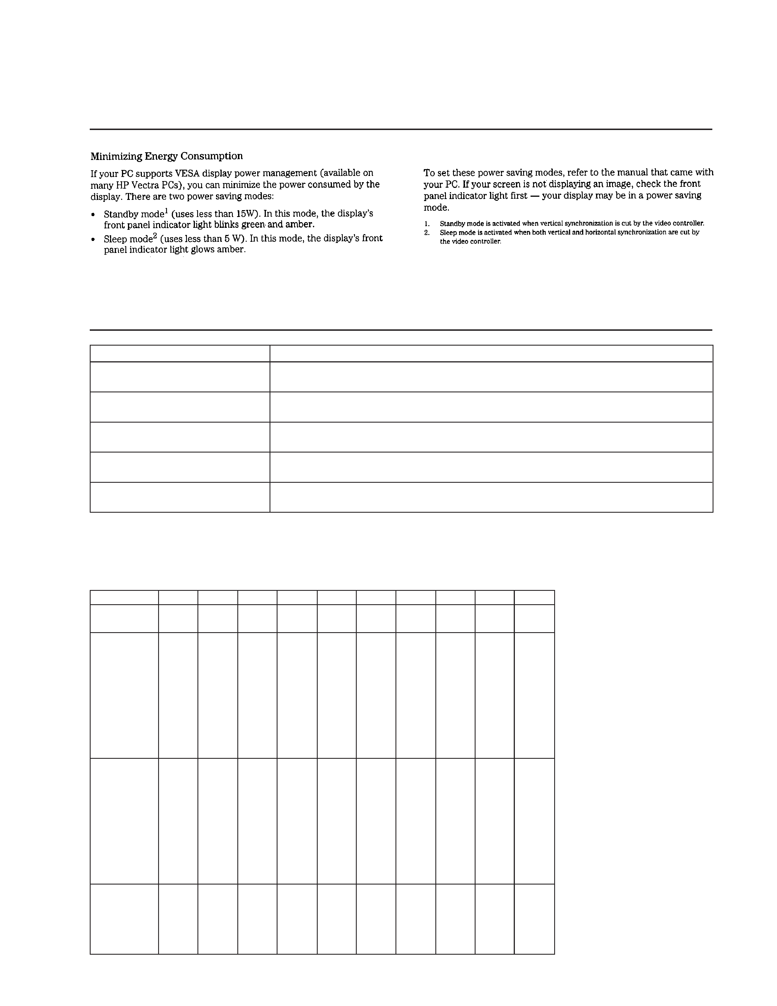
POWER SAVING FUNCTION
DIAGNOSIS
Failre
+B failure
Horizontal / Vertical Deflection failure,
Thermal protector
ABL protector
HV failure
Aging / Self Test
Power LED
Yellow
Off
(0.5 sec)
(0.5 sec)
Yellow
Off
(1.5 sec)
(0.5 sec)
Yellow
Off
(0.5 sec)
(1.5 sec)
Yellow
Off
Yellow
Off
(0.25 sec)
(0.5 sec)
(0.25 sec)
(1.25 sec)
Yellow
Off
Green
Off
(0.5 sec)
(0.5 sec)
(0.5 sec)
(0.5 sec)
Aging Mode (Video Aging) : During Power Save, press "MENU" key for longer than 2 second.
Self Test (OSD Color Bar)
: During Power Save, press "CONTRAST" + (
>) key for longer than 2 second.
Reliability Check Mode
: During Power Save, press "CONTRAST" (
.) key for longer than 2 second.
TIMING SPECIFICATION

4
D2846
Note: Hand degauss must be used on stand-by or power-off condition.
This model has an automatic earth magnetism correction function by using an earth
magnetism sensor and a LCC coil. When using a hand degauss while monitor (LCC
coil) is being operated, it sometimes gets magnetized, and the system may not work
properly as a result.
TABLE OF CONTENTS
Section
Title
Page
1. GENERAL ...................................................................
5
2. DISASSEMBLY
2-1.
Cabinet Removal .................................................. 13
2-2.
D Board Removal ................................................ 13
2-3.
G Board Removal ................................................ 14
2-4.
A Board Removal ................................................ 14
2-5.
L Board Removal ................................................. 15
2-6.
I/O Terminal Board Removal ............................... 15
2-7.
Service Position .................................................... 16
2-8.
H and J Boards Removal ..................................... 16
2-9.
Picture Tube Removal ......................................... 17
3. SAFETY RELATED ADJUSTMENT ............ 18
4. ADJUSTMENTS ...................................................... 19
5. DIAGRAMS
5-1.
Block Diagrams .................................................... 21
5-2.
Frame Shcematic Diagram .................................... 27
5-3.
Circuit Boards Location ........................................ 29
5-4.
Schematic Diagrams and Printed Wiring Boards ..... 29
(1) Schematic Diagram of D Board ........................... 33
(2) Schematic Diagrams of G, GA, H, J,
L and U3 Boards .................................................. 37
(3) Schematic Diagram of A Board ........................... 44
5-5.
Semiconductors .................................................... 49
6. EXPLODED VIEWS
6-1.
Chassis ................................................................. 51
6-2.
Picture Tube ......................................................... 52
6-3.
Packing Materials ................................................ 53
7. ELECTRICAL PARTS LIST ............................ 54
5
SECTION
1
GENERAL
The
operating
instructions
mentioned
here
are
partial
abstracts
from
the
Operating
Instruction
Manual.
The
page
numbers
of
the
Operating
Instruction
Manual
remain
as
in
the
manual.