CHASSIS
SERVICE MANUAL
SPECIFICATIONS
US Model
Canadian Model
AEP Model
EQ Model
SH Model
J Model
Chassis No. SCC-L04K-A
D1626HT
R
COLOR MONITOR
N3
Picture tube
0.25 - 0.27 mm aperture grill pitch,
21 inches measured diagonally,
90 degree deflection
Phosphor Type
P22
Transmission Ratio
Approx. 39%
Faceplate
Anti Reflective (AR)/Anti Static (AS)
coating
Viewable image size
Approx. 403.8
× 302.2 mm (w/h)
(16
× 12 in.) 19.8" viewing image
Resolution
Horizontal
Max. 1600 dots
Vertical
Max. 1200 lines
Display picture size
Approx. 388
× 291 mm (w/h)
(15 3/8
× 11 1/2 in.)
or
Approx. 364
× 291 mm (w/h)
(14 3/8
× 11 1/2 in.)
Input signal
Video
Analog RGB (75
typical)
0.7 Vp-p, Positive
Sync
External HD/VD, Composite
Polarity Free TTL
Video Composite (Sync on green)
0.3 Vp-p, Negative
Deflection frequency
Horizontal
30 to 107 kHz
Vertical
48 to 160 Hz
AC input voltage/current
100 to 240 V, 50 60 Hz, 2.0 1.0 A
Inrush current
120 VAC/50 A
240 VAC/80 A
Power consumption
Maximum
160 W
Nominal
120 W, 409 BTU/h
Dimensions
498
× 505 × 474 mm (w/h/d)
(19 5/8
× 20 × 18 3/4 in.)
Net weight
Approx. 31 kg (68 lb 5 oz)
Shipping weight
37 kg (81 lb 9 oz)
Environmental Temperature
Operating
10° to 40° C (50° to 104° F)
Non-operating
0° to 60° C (32° to 140° F)
Environmental Humidity
Operating
10% to 80% (Non-condensing)
Non-operating
5% to 90% (Non-condensing)
Design and specifications are subject to change without notice.
D1626HT
2
SAFETY CHECK-OUT
(US Model only)
LEAKAGE TEST
The AC leakage from any exposed metal part to earth ground
and from all exposed metal parts to any exposed metal part
having a return to chassis, must not exceed 0.5 mA (500
microampers).
Leakage current can be measured by any one of three meth-
ods.
1. A commercial leakage tester, such as the Simpson 229 or
RCA WT-540A. Follow the manufacturers' instructions to
use these instruments.
2. A battery-operated AC milliammeter. The Data Precision 245
digital multimeter is suitable for this job.
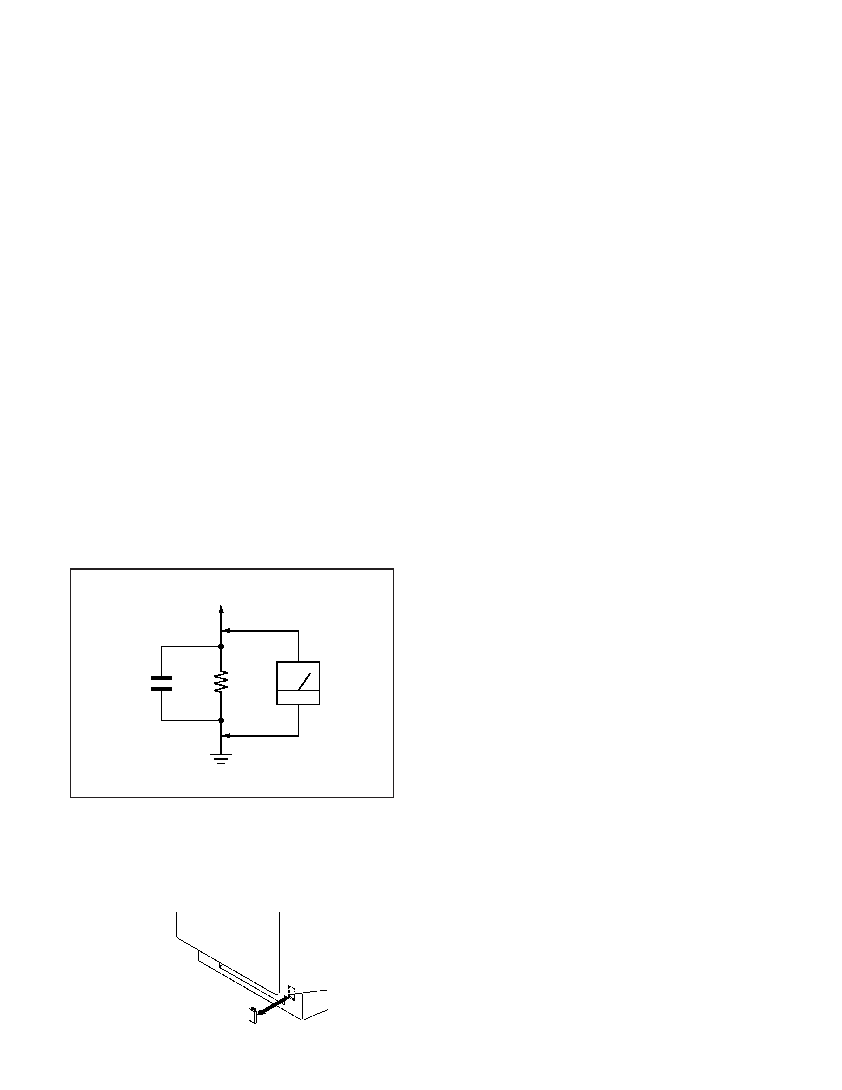
3. Measuring the voltage drop across a resistor by means of a
VOM or battery-operated AC voltmeter. The "limit" indica-
tion is 0.75 V, so analog meters must have an accurate low-
voltage scale. The Simpson 250 and Sanwa SH-63Trd are ex-
amples of a passive VOMs that are suitable. Nearly all battery
operated digital multimeters that have a 2 V AC range are suit-
able. (See Fig. A)
WARNING!!
NEVER TURN ON THE POWER IN A CONDITION IN
WHICH THE DEGAUSS COIL HAS BEEN REMOVED.
SAFETY-RELATED COMPONENT WARNING!!
COMPONENTS IDENTIFIED BY SHADING AND MARK
¡ ON THE SCHEMATIC DIAGRAMS, EXPLODED
VIEWS AND IN THE PARTS LIST ARE CRITICAL FOR
SAFE OPERATION. REPLACE THESE COMPONENTS
WITH SONY PARTS WHOSE PART NUMBERS AP-
PEAR AS SHOWN IN THIS MANUAL OR IN SUPPLE-
MENTS PUBLISHED BY SONY. CIRCUIT ADJUST-
MENTS THAT ARE CRITICAL FOR SAFE OPERATION
ARE IDENTIFIED IN THIS MANUAL. FOLLOW THESE
PROCEDURES WHENEVER CRITICAL COMPO-
NENTS ARE REPLACED OR IMPROPER OPERATION
IS SUSPECTED.
AVERTISSEMENT!!
NE JAMAIS METTRE SOUS TENSION QUAND LA
BOBINE DE DEMAGNETISATION EST ENLEVÉE.
ATTENTION AUX COMPOSANTS RELATIFS À LA
SÉCURITÉ!!
LES COMPOSANTS IDENTIFIÉS PAR UNE TRAME ET
UNE MARQUE
¡ SONT CRITIQUES POUR LA
SÉCURITÉ. NE LES REMPLACER QUE PAR UNE PIÈCE
PORTANT LE NUMÉRO SPECIFIÉ. LES RÉGLAGES DE
CIRCUIT DONT L'IMPORTANCE EST CRITIQUE POUR
LA
SÉCURITÉ
DU
FONCTIONNEMENT
SONT
IDENTIFIÉS DANS LE PRÉSENT MANUEL. SUIVRE CES
PROCÉDURES LORS DE CHAQUE REMPLACEMENT
DE COMPOSANTS CRITIQUES, OU LORSQU'UN
MAUVAIS FONCTIONNE-MENT EST SUSPECTÉ.
After correcting the original service problem, perform the fol-
lowing safety checks before releasing the set to the customer:
1. Check the area of your repair for unsoldered or poorly-sol-
dered connections. Check the entire board surface for solder
splashes and bridges.
2. Check the interboard wiring to ensure that no wires are
"pinched" or contact high-wattage resistors.
3. Check that all control knobs, shields, covers, ground straps,
and mounting hardware have been replaced. Be absolutely
certain that you have replaced all the insulators.
4. Look for unauthorized replacement parts, particularly transis-
tors, that were installed during a previous repair. Point them
out to the customer and recommend their replacement.
5. Look for parts which, though functioning, show obvious signs
of deterioration. Point them out to the customer and recom-
mend their replacement.
6. Check the line cords for cracks and abrasion. Recommend the
replacement of any such line cord to the customer.
7. Check the B+ and HV to see if they are specified values. Make
sure your instruments are accurate; be suspicious of your HV
meter if sets always have low HV.
8. Check the antenna terminals, metal trim, "metallized" knobs,
screws, and all other exposed metal parts for AC Leakage.
Check leakage as described below.
1.5 k
0.15
µF
AC
Voltmeter
(0.75 V)
To Exposed Metal
Parts on Set
Earth Ground
Fig. A. Using an AC voltmeter to check AC leakage.
CAUTION ON DAS (ECS) CONNECTOR
· The connector for DAS (ECS) adjustment is provided inside the
cover shown below. Be careful with an electrical shock when
connecting the connector with the power supplied. Also, return
the removed cover to the home position.
Rear side
D1626HT
3
MODE AT PRODUCTION
MODE 1
MODE 2
MODE 3
MODE 4
MODE 5
MODE FOR CUSTOMER
VESA
VESA
VESA
VESA
VESA
RESOLUTION
1024 X 768
1024 X 768
1280 X 1024
1280 X 1024
1600 X 1200
CLOCK
78.750 MHz
94.500 MHz
135.000 MHz
157.500 MHz
229.500 MHz
-- HORIZONTAL --
H-FREQ
60.023 kHz
68.677 kHz
79.976 kHz
91.146 kHz
106.250 kHz
usec
usec
usec
usec
usec
H. TOTAL
16.66
14.561
12.504
10.971
9.412
H. BLK
3.657
3.725
3.022
2.844
2.44
H. FP
0.203
0.508
0.119
0.406
0.279
H. SYNC
1.219
1.016
1.067
1.016
0.837
H. BP
2.235
2.201
1.837
1.422
1.325
H. ACTIV
13.003
10.836
9.481
8.127
6.972
-- VERTICAL --
V. FREQ(HZ)
75.029 Hz
84.997 Hz
75.025 Hz
85.024 Hz
85.000 Hz
lines
lines
lines
lines
lines
V. TOTAL
800
808
1066
1072
1250
V. BLK
32
40
42
48
50
V. FP
1
1111
V. SYNC
3
3333
V. BP
28
36
38
44
46
V. ACTIV
768
768
1024
1024
1200
-- SYNC --
INT(G)
NO
NO
NO
NO
NO
EXT(H/V)/POLARITY
YES P/P
YES P/P
YES P/P
YES P/P
YES P/P
EXT(CS) /POLARITY
NO
NO
NO
NO
NO
INT/NON INT
NON INT
NON INT
NON INT
NON INT
NON INT
POWER SAVING FUNCTION
This monitor has three Power Saving modes. By sensing the absence of a
video signal from the computer, it reduces power consumption as follows.
Power
consumption
160 W
100 W
15 W
5 W
0 W
--
Recovery
time
--
Approx.
3 sec.
Approx.
3 sec.
Approx.
10 sec.
--
--
u
indicator
Green
Green and orange
alternate
Green and orange
alternate
Orange
Off
Orange flashing
Power
consumption
mode
Normal
operation
Standby
(1st mode)
Suspend
(2nd mode)
Active-off
(3rd mode)
Power-off
Failure mode
1
2
3
4
5
6
Failre
+B failure
Horizontal / Vertical Deflection failure,
Thermal protector
ABL protector
HV failure
Aging / Self Test
Power LED
Yellow
Off
(0.5 sec)
(0.5 sec)
Yellow
Off
(1.5 sec)
(0.5 sec)
Yellow
Off
(0.5 sec)
(1.5 sec)
Yellow
Off
Yellow
Off
(0.25 sec)
(0.5 sec)
(0.25 sec)
(1.25 sec)
Yellow
Off
Green
Off
(0.5 sec)
(0.5 sec)
(0.5 sec)
(0.5 sec)
Aging Mode (Video Aging) : During Power Save, press "MENU" key for longer than 2 second.
Self Test (OSD Color Bar)
: During Power Save, press "CONTRAST" + (
>) key for longer than 2 second.
Reliability Check Mode
: During Power Save, press "CONTRAST" (
.) key for longer than 2 second.
DIAGNOSIS
TIMING SPECIFICATION
Note
If no video signal is input to the monitor, the "NO INPUT SIGNAL"
message appears (page 13). After about 60 seconds, the Power Saving
function automatically puts the monitor into
Active-off mode and the u indicator lights up orange. Once the monitor
detects horizontal and vertical sync signals, the monitor automatically
resumes normal operation mode.
97.10.29 VER.

D1626HT
4
Note: Hand degauss must be used on stand-by or power-off condition.
This model has an automatic earth magnetism correction function by using an earth
magnetism sensor and a LCC coil. When using a hand degauss while monitor (LCC
coil) is being operated, it sometimes gets magnetized, and the system may not work
properly as a result.
TABLE OF CONTENTS
Section
Title
Page
1. GENERAL ...................................................................
5
2. DISASSEMBLY
2-1.
Cabinet Removal .................................................. 13
2-2.
D Board Removal ................................................ 13
2-3.
G Board Removal ................................................ 14
2-4.
A Board Removal ................................................ 14
2-5.
L Board Removal ................................................. 15
2-6.
I/O TERMINAL Board Removal ......................... 15
2-7.
Service Position .................................................... 16
2-8.
H and J Boards Removal ..................................... 16
2-9.
Picture Tube Removal ......................................... 17
3. SAFETY RELATED ADJUSTMENT ............ 18
4. ADJUSTMENTS ...................................................... 19
5. DIAGRAMS
5-1.
Block Diagrams .................................................... 21
5-2.
Frame Shcematic Diagram .................................... 27
5-3.
Circuit Boards Location ........................................ 29
5-4.
Schematic Diagrams and Printed Wiring Boards ..... 29
(1) Schematic Diagram of D Board ........................... 33
(2) Schematic Diagrams of G, GA, H, J
and L Boards ........................................................ 37
(3) Schematic Diagram of A Board ........................... 44
5-5.
Semiconductors .................................................... 49
6. EXPLODED VIEWS
6-1.
Chassis ................................................................. 51
6-2.
Picture Tube ......................................................... 52
6-3.
Packing Materials ................................................ 53
7. ELECTRICAL PARTS LIST ............................ 54
5
SECTION
1
GENERAL
The
operating
instructions
mentioned
here
are
partial
abstracts
from
the
Operating
Instruction
Manual.
The
page
numbers
of
the
Operating
Instruction
Manual
remain
as
in
the
manual.
5
Getting Started
EN
F
ES
D
J
C s
C t
PL
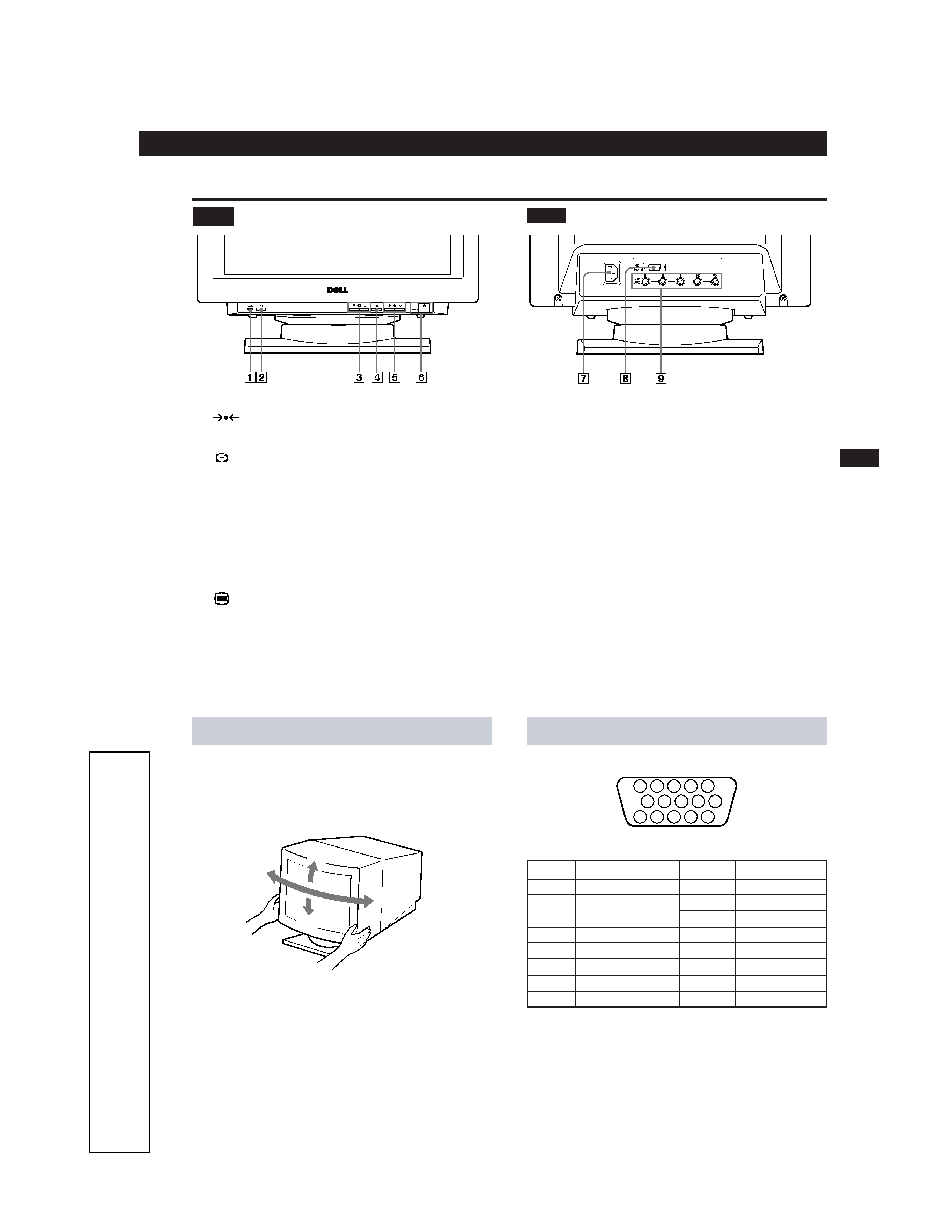
Video Input 1 Connector (HD15)
Pin No. Signal
1
Red
2
Green (Composite
Sync on Green)
3
Blue
4
ID (ground)
5
DDC Ground*
6
Red Ground
7
Green Ground
Pin No.
Signal
8
Blue Ground
9
DDC +5V*
10
Ground
11
ID (ground)
12
SDA (serial data)
13
Horizontal Sync
14
Vertical Sync
15
SCL (serial clock)
Use of the Tilt/Swivel
With the tilt/swivel, you can adjust this monitor to any desired
angle within 180° horizontally and 20° vertically.
To turn the monitor vertically and horizontally, hold it at the
bottom with both hands as shown below.
Parts and Controls
Rear
1
(RESET) button (pages 7 and 11)
Resets the adjustments to the factory settings.
2
(AUTO SIZING AND CENTERING) button
(page 6)
Automatically adjusts the size and centering of the
images.
3 ¨ (BRIGHTNESS) ./> buttons (page 6)
Adjust the picture brightness.
Operate as the
./> buttons when adjusting other
items.
4
(MENU) button (page 7)
Displays the MENU OSD.
5 > (CONTRAST) ?// buttons (page 6)
Adjust the contrast.
Operate as the
?// buttons when adjusting other items.
6 u (POWER) switch and indicator (page 12)
Turns the monitor on and off.
The indicator lights up green when the monitor is on,
and lights up orange when the monitor is in Power
Saving mode.
7 AC IN connector
Provides AC power to the monitor.
8 Video input 1 connector (HD15)
Inputs RGB video signals and SYNC signals
9 Video input 2 connector (5 BNC)
Inputs RGB video signals (0.7 Vp-p, positive) and SYNC
signals.
Front
Getting Started
15
°
90
°
90
°
5
°
* Display Data Channel (DDC) standard of VESA.
5 4
3 2 1
6
7
8
9
10
11
12
13
14
15