1
SERVICE MANUAL
CSD-MP100
CD STEREO RADIO CASSETTE RECORDER
Other Specifications
CD player section
System
Compact disc digital audio system
Laser diode properties
Material: GaAlAs
Wave length: 780 nm
Emission duration: Continuous
Laser output: Less than 44.6 µW
(This output is the value measured at a distance of
about 200 mm from the objective lens surface on
the optical pick-up block with 7 mm aperture.)
Spindle speed
200 r/min (rpm) to 500 r/min (rpm) (CLV)
Number of channels
2
Frequency response
20 - 20,000 Hz +1/2 dB
Wow and flutter
Below measurable limit
SPECIFICATIONS
Radio section
Frequency range
FM: 87.5 - 108 MHz
US, CND model:
AM: 530 - 1,710 kHz
TW, AUS, KR model:
AM: 531 - 1,611 kHz
AEP, UK, E4, E15, SP model:
AM: 531 - 1,611 kHz (9 kHz step)
530 - 1,610 kHz (10 kHz step)
Antennas
FM: Telescopic antenna
AM: Built-in ferrite bar antenna
Cassette-corder section
Recording system
4-track 2 channel stereo
Fast winding time
Approx. 120 sec. with Sony cassette C-60
Frequency response
TYPE I (normal): 80 - 10,000 Hz
Ver 1.0 2003. 06
9-877-441-01
2003F04-1
© 2003. 06
AUDIO POWER SPECIFICATIONS (US model)
POWER OUTPUT AND TOTAL
HARMONIC DISTORTION
With 8-ohm loads, both channels driven from
150 - 6,300 Hz; rated 1.5 W per channel-
minimum RMS power, with no more than 10%
total harmonic distortion in AC operation.
US Model
Canadian Model
AEP Model
UK Model
E Model
Australian Model
CD
Model Name Using Similar Mechanism CFD-S200
Section
CD Mechanism Type
KSM-213RDP
Optical Pick-up Name
KSS-213R
TC
Model Name Using Similar Mechanism NEW
Section Tape Transport Mechanism Type
MF-MP100
Continued on next page
Sony Corporation
Personal Audio Company
Published by Sony Engineering Corporation
2
General
Speaker
Full range: 10 cm dia.,
4
, cone type (2)
Power output
2.0 W + 2.0 W (at 4
, 10%
harmonic distortion)
Power requirements
For CD stereo radio cassette recorder:
US, CND, TW model:
120 V AC, 60 Hz
E4 model
200 - 240 V AC, 50/60 Hz
E15 model
220 - 240 V AC, 50/60 Hz
AEP, UK, AUS, SP model:
230 V AC, 50 Hz
KR model:
220 V AC, 60 Hz
9 V DC, 6 size D (R20) batteries
For remote control:
3 V DC, 2 size AA (R6) batteries
Power consumption
AC 10 W
Battery life
For CD stereo radio cassette recorder:
FM recording
Sony R20P: approx. 13.5 h
Sony alkaline LR20: approx. 24 h
Tape playback
Sony R20P: approx. 7.5 h
Sony alkaline LR20: approx. 15 h
CD playback
Sony R20P: approx. 2.5 h
Sony alkaline LR20: approx. 7 h
Dimensions
Approx. 390
× 170 × 259.5 mm (w/h/d)
(15 3/8
× 6 3/4 × 10 1/4 inches) (incl. projecting parts)
Mass
Approx. 4 kg (8 lb. 13 oz.) (incl. batteries)
Supplied accessories
AC power cord (1)
Remote control (RM-Z1S002) (1)
Design and specifications are subject to change without
notice.
CSD-MP100
SAFETY-RELATED COMPONENT WARNING!!
COMPONENTS IDENTIFIED BY MARK 0 OR DOTTED LINE
WITH MARK 0 ON THE SCHEMATIC DIAGRAMS AND IN
THE PARTS LIST ARE CRITICAL TO SAFE OPERATION.
REPLACE THESE COMPONENTS WITH SONY PARTS WHOSE
PART NUMBERS APPEAR AS SHOWN IN THIS MANUAL OR
IN SUPPLEMENTS PUBLISHED BY SONY.
CAUTION
Use of controls or adjustments or performance of proce-
dures other than those specified herein may result in haz-
ardous radiation exposure.
Flexible Circuit Board Repairing
· Keep the temperature of the soldering iron around 270°C during
repairing.
· Do not touch the soldering iron on the same conductor of the
circuit board (within 3 times).
· Be careful not to apply force on the conductor when soldering
or unsoldering.
Notes on Chip Component Replacement
· Never reuse a disconnected chip component.
· Notice that the minus side of a tantalum capacitor may be dam-
aged by heat.
NOTES ON HANDLING THE OPTICAL PICK-UP BLOCK
OR BASE UNIT
The laser diode in the optical pick-up block may suffer electrostatic
breakdown because of the potential difference generated by the
charged electrostatic load, etc. on clothing and the human body.
During repair, pay attention to electrostatic breakdown and also use
the procedure in the printed matter which is included in the repair
parts.
The flexible board is easily damaged and should be handled with
care.
NOTES ON LASER DIODE EMISSION CHECK
The laser beam on this model is concentrated so as to be focused on
the disc reflective surface by the objective lens in the optical pick-
up block. Therefore, when checking the laser diode emission,
observe from more than 30 cm away from the objective lens.
ATTENTION AU COMPOSANT AYANT RAPPORT
À LA SÉCURITÉ!!
LES COMPOSANTS IDENTIFIÉS PAR UNE MARQUE 0 SUR LES
DIAGRAMMES SCHÉMATIQUES ET LA LISTE DES PIÈCES SONT
CRITIQUES POUR LA SÉCURITÉ DE FONCTIONNEMENT. NE
REMPLACER CES COMPOSANTS QUE PAR DES PIÈCES SONY
DONT LES NUMÉROS SONT DONNÉS DANS CE MANUEL OU
DANS LES SUPPLÉMENTS PUBLIÉS PAR SONY.
·Abbreviation
CND
: Canadian model
E4
: AC 200-240V area in E model
E15
: AC 220-240V area in E model
TW
: Taiwan model
AUS: Australian model
SP
: Singapore model
KR
: Korean model
This Compact Disc player is classified as a CLASS 1
LASER product.
The CLASS 1 LASER PRODUCT mark is located at the
bottom.
CLASS 1 LASER PRODUCT
LUOKAN 1 LASER LAITE
KLASS 1 LASER APPARAT
AEP, UK, E, AUS model

3
CSD-MP100
About "MP3"
What is the MP3
MP3 (MPEG 1 Audio Layer-3) is a standard technology and format
for compressing a sound sequence. The file is compressed to about
1/10 of its original size.
Sounds outside the range of human hearing are compressed while
the sounds we can hear are not compressed.
Playable "MP3" files on the player
You can only play MP3 files recorded by following requirements.
Usable media
CD-Rs and CD-RWs
Usable disc format
You can use ISO 9660 Level 1, Level 2 and Joliet extension format
discs. In some cases, MP3 files that are recorded in a format other
than these formats may not play normally or the file and folder
names may not be displayed correctly.
The major specifications of the usable disc format are as follows:
· Maximum directory steps: 8
· Usable characters for a file/folder name: A - Z, a - z, 0 - 9 and
_ (underscore)
· Maximum number of characters for a file name: 16 (8) includ-
ing quotation marks and a 3-character extension code
Notes
·When naming, be sure to add the file extension "mp3" to the file
name.
· If you put the extension "mp3" to a file other than an MP3 file,
the player cannot recognize the file properly and will generate
random noise that could damage your speaker.
·The file name does not correspond to the ID tag.
The usable number of folders/files
· Maximum number of folders and files: 512 (in total)
Settings for compression software and writing software
·To compress a source for an MP3 file, we recommend setting
the transfer bit rate of the compression software to "44.1 kHz",
"128 kbps" and "Constant Bit Rate".
·To record up to the maximum capacity, set to the "halting of
writing".
·To record at one time up to the maximum capacity on media that
has nothing recorded it, set to "Disc at Once".
Notes for saving files on the media
When the disc is inserted, the player reads all the files on that disc.
If there are many folders or non-MP3 files on the disc, it may take a
long time for play to begin or for the next MP3 file to start play.
Do not save unnecessary folders or files other than MP3 ones in the
disc to be used for MP3 listening.
We recommend that you do not save other types of files
or unnecessary folders on a disc that has MP3 files.
About "ID3 tag"
ID3 tag is a format for adding certain information (track title, artist
name and album title, etc.) to MP3 files.
This player conforms to Version 1.1 of the ID3 tag information,
"track title", "artist name" and "album title" can be displayed.
Note
If you use a version other than 1.1, ID3 tag information will not be
displayed correctly.

4
TABLE OF CONTENTS
1. SERVICING NOTES ......................................................... 5
2. GENERAL ............................................................................ 6
3. DISASSEMBLY
3-1. Cabinet Rear Assy ............................................................... 9
3-2. Chassis CD Assy ................................................................. 9
3-3. Main Board, Tape Board ................................................... 10
3-4. Tape Mechanism Deck ...................................................... 10
3-5. Cassette Lid Assy .............................................................. 11
3-6. Display Board ................................................................... 11
3-7. CD Block Assy .................................................................. 12
3-8. CD/MP3 Board ................................................................. 12
3-9. Optical Pick-up ................................................................. 13
3-10. Tuner Board ....................................................................... 13
3-11. Power Trans Board ............................................................ 14
3-12. HRP301, HE301, Pinch Roller Arm Assy ......................... 14
3-13. M301, Belt ........................................................................ 15
4. MECHANICAL ADJUSTMENTS ............................... 16
5. ELECTRICAL ADJUSTMENTS
Tape Section .......................................................................... 16
Tuner Section ......................................................................... 17
CD Section ............................................................................ 18
6. DIAGRAMS
6-1. IC Pin Description ............................................................. 19
6-2. Block Diagram CD Section ......................................... 23
6-3. Block Diagram Main Section ...................................... 24
6-4. Circuit Boards Location .................................................... 25
6-5. Printed Wiring Board CD Section ............................... 26
6-6. Schematic Diagram CD Section .................................. 28
6-7. Printed Wiring Board Tuner Section ........................... 29
6-8. Schematic Diagram Tuner Section .............................. 30
6-9. Printed Wiring Board Main Section ............................ 31
6-10. Schematic Diagram Main Section (1/2) ...................... 32
6-11. Schematic Diagram Main Section (2/2) ...................... 33
6-12. Printed Wiring Board Tape Section ............................. 34
6-13. Schematic Diagram Tape Section ............................... 35
6-14. Printed Wiring Board Display Section ........................ 36
6-15. Schematic Diagram Display Section ........................... 37
6-16. Printed Wiring Boards Power Supply Section ............ 38
6-17. Schematic Diagram Power Supply Section ................. 40
6-18. IC Block Diagrams ............................................................ 41
7. EXPLODED VIEWS
7-1. Main Board Section .......................................................... 44
7-2. Cabinet Front (1) Section .................................................. 45
7-3. Cabinet Front (2) Section .................................................. 46
7-4. Chassis CD Section ........................................................... 47
7-5. Cabinet Rear Section ......................................................... 48
7-6. Tape Mechanism Section .................................................. 49
7-7. CD Mechanism Section .................................................... 50
8. ELECTRICAL PARTS LIST ......................................... 51
CSD-MP100
5
CSD-MP100
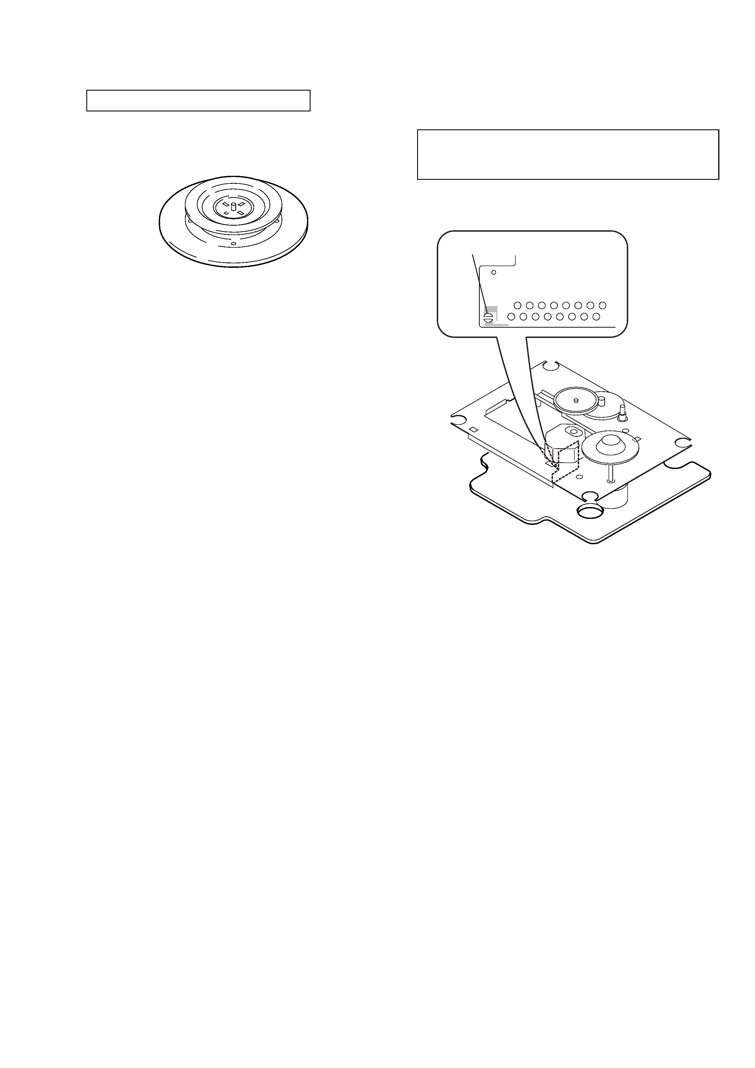
CHUCK PLATE JIG ON REPAIRING
On repairing CD section, playing a disc without the lid (CD), use
Chuck Plate Jig.
· Code number of Chuck Plate Jig: X-4918-255-1
SECTION 1
SERVICING NOTES
PRECAUTION TO REPLACE OPTICAL BLOCK
(KSM-213RDP)
solder
Body or clothes electrostatic potential could ruin laser diode
in the optical block. Be sure ground body and workbench,
and use care the clothes do not touch the diode.
1) After the connection, remove solder shown in the right figure.