No.
DATA
CONTENTS
#1
2000. 3
Adds ten parts of exploded view owing to addition of the black model. (P.5-1, 24)
#2
2000.10 Supply of LAMP UNIT was changed. (P.5-1)
#3
2000.10 Parts number clerical error correction. (P.5-1)
#4
2000.10 Information label was added by change in place of production.
[Made in Taiwan
Thailand] (P.5-1)
#5
2004. 2
Change the part number (No.52) of AC ADAPTOR in the expladed views. (P.24)
MODEL NAME : CPD-M151
SERVICE MANUAL
PARTS No. : 9-978-665-03
MODIFICATION HISTORY
* Blue characters are linking.
SERVICE MANUAL
SPECIFICATIONS
MICROFILM
US Model
Canadian Model
AEP Model
Chassis No. SCC-G25H-A
TFT LCD COLOR COMPUTER DISPLAY
CPD-M151
LCD panel
Panel type: a-Si TFT Active Matrix
Picture size: 15 inches (38 cm)
Input signal format
RGB operating frequency*
fh: 30 61 kHz
fv: 50 75 Hz
Pixel efficiency
99.99 %
Resolution
H: max. 1024 dots
V: max. 768 lines
Power requirements
Operation:
AC 100 240 V, 50 60 Hz
Input:
DC 12 V (using the AC adapter)
Power consumption
Monitor only: Max. 25 W
Including the AC adapter:
Max. 35 W
Dimensions (w/h/d)
With the stand:
Approx. 395
× 358 × 173 mm
(15 5/8
× 14 1/8 × 6 7/8 in.)
Without the stand (upright):
Approx. 395
× 289 × 76 mm
(15 5/8
× 11 1/2 × 3 in.)
Without the stand (25
° tilted):
Approx. 395
× 274 × 202 mm
(15 5/8
× 10 7/8 × 8 in.)
Mass
Approx. 5.1 kg (11 lb 4 oz)
including the stand
Plug & Play
DDC/DDC1/DDC2B
Supplied accessories
· LCD monitor (1)
· Rear cover (1)
· Power cord (1)
· AC adapter (1)
· HD15 video signal cable (1)
· Macintosh adapter (1)
· Rubber pads (2)
· Windows Monitor Information
Disk/Utility Disk (1)
· Macintosh Utility Disk (1)
· Warranty card (1)
· These operating instructions (1)
5 4
3 2 1
6
7
8
9
10
11
12
13
14
15
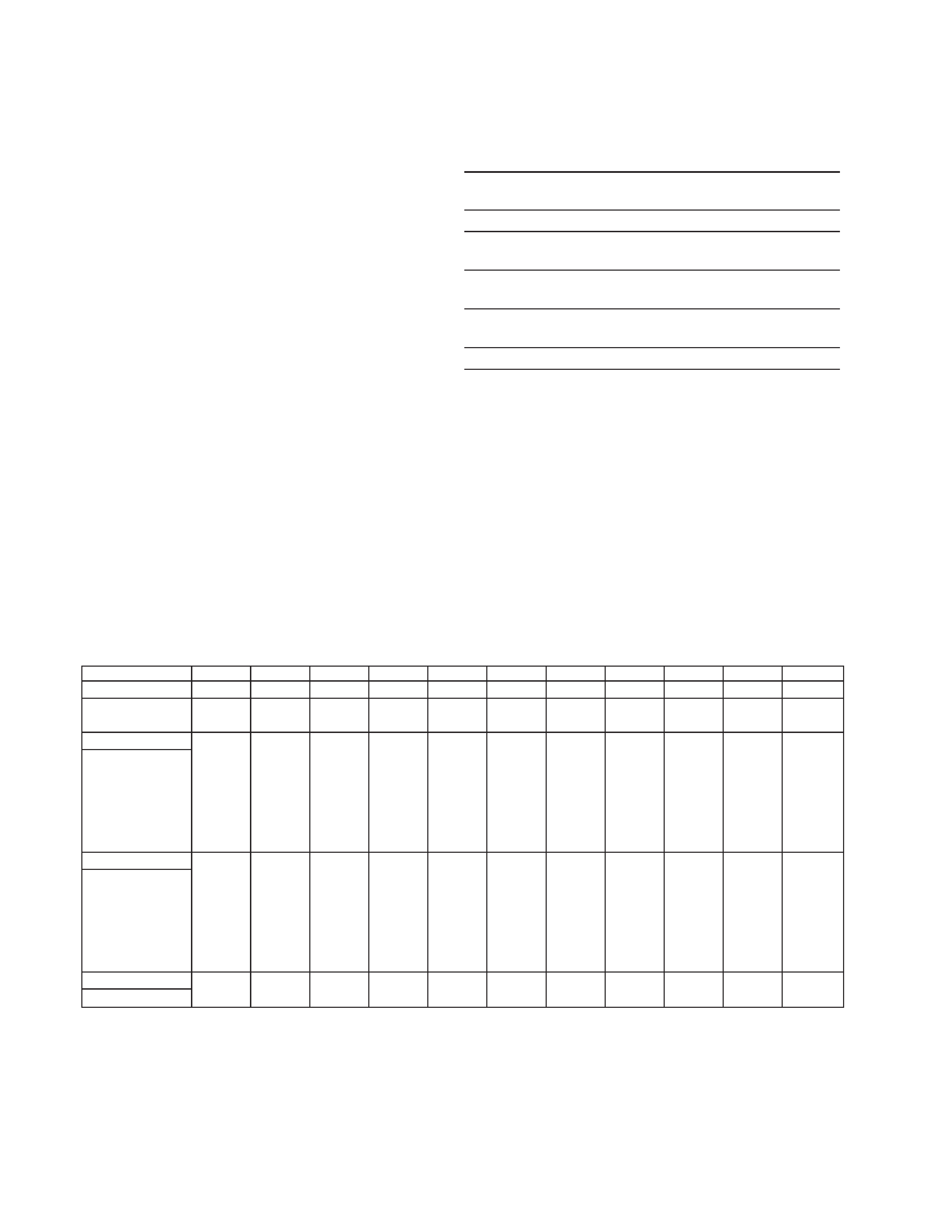
Pin No.
1
2
3
4
5
6
7
Pin No.
8
9
10
11
12
13
14
15
Signal
Red
Green
(Composite Sync
on Green)
Blue
ID (Ground)
DDC Ground*
Red Ground
Green Ground
Signal
Blue Ground
DDC + 5V*
Ground
ID (Ground)
Bi-Directional
Data (SDA)*
H. Sync
V. Sync
Data Clock (SCL)*
HD15 pin assignment
*
Display Data Channel (DDC) Standard of VESA
* Recommended horizontal and vertical timing
conditions
Horizontal sync width duty should be more than 4.8% of total
horizontal time or 0.8 µsec., whichever is larger.
Horizontal blanking width should be more than 2.5 µsec.
Vertical blanking width should be more than 450 µsec.
Design and specifications are subject to change without
notice.
CPD-M151
2
TIMING SPECIFICATION
MODE AT PRODUCTION
MODE 1
MODE 2
MODE 3
MODE 4
MODE 5
MODE 6
MODE 7
MODE 8
MODE 9
MODE 10
MODE 11
SIGNAL MODE
NEC (70Hz)
VGA (Graph) VESA (75Hz)
VGA (TEXT)
VESA (60Hz) VESA (75Hz)
PMAC 16"
VESA (60Hz)
VESA (70Hz) VESA (75Hz)
PMAC 19"
RESOLUTION
640 X 400
640 X 480
640 X 480
720 X 400
800 X 600
800 X 600
832 X 624
1024 X 768
1024 X 768
1024 X 768
1024 X 768
CLOCK
25.180 MHz 25.175 MHz 31.500 MHz 28.322 MHz 40.000 MHz 49.500 MHz 57.285 MHz 65.000 MHz 75.000 MHz 78.750 MHz 80.000 MHz
-- HORIZONTAL --
H-FREQ
31.48 kHz
31.47 kHz
37.50 kHz
31.47 kHz
37.88 kHz
46.88 kHz
49.73 kHz
48.36 kHz
56.47 kHz
60.02 kHz
60.24 kHz
usec
usec
usec
usec
usec
usec
usec
usec
usec
usec
usec
H. TOTAL
31.771
31.778
26.667
31.777
26.400
21.333
20.110
20.677
17.707
16.660
16.660
H. SYNC
2.542
3.813
2.032
3.813
3.200
1.616
1.117
2.092
1.813
1.219
1.200
H. BP
2.859
1.907
3.810
1.907
2.200
3.232
3.910
2.462
1.920
2.235
2.200
H. ACTIV
25.417
25.422
20.317
25.422
20.000
16.162
14.524
15.754
13.653
13.003
12.800
-- VERTICAL --
V. FREQ(Hz)
70.1 Hz
59.9 Hz
75.0 Hz
70.1 Hz
60.3 Hz
75.0 Hz
74.6 Hz
60.0 Hz
70.1 Hz
75.0 Hz
74.9 Hz
lines
lines
lines
lines
lines
lines
lines
lines
lines
lines
lines
V. TOTAL
449
525
500
449
628
625
667
806
806
800
804
V. SYNC
2
2
3243
3
6
6
3
3
V. BP
36
33
16
35
23
21
39
29
29
28
30
V. ACTIV
400
480
480
400
600
600
624
768
768
768
768
-- SYNC --
(H/V)/POLARITY
N/N
N/N
N/N
N/P
P/P
P/P
N/N
N/N
N/N
P/P
N/N
Power Saving Function
This monitor meets the power-saving guidelines set by
VESA and
ENERGY STAR, as well as the more stringent
NUTEK .
If the monitor is connected to a computer or video graphics
board that is VESA DPMS (Display Power Management
Signaling) compliant, the monitor will automatically reduce
power consumption in three stages as shown right.
You can set the delay time before the monitor enters the
power saving mode using the OSD. Set the time according
to "Setting the Power Saving Delay Time" on page 1-7.
*
Power consumption of the monitor only. The figures in
parentheses are power consumption of the monitor including
the AC adapter.
** "Sleep" and "deep sleep" are power saving modes defined by
the Environmental Protection Agency.
*** When your computer enters the power saving mode, the input
signal is cut and NO INPUT SIGNAL appears on the screen.
After the time set in "Changing the Power Saving Delay Time"
(page 1-7) has elapsed, the monitor enters the power saving
mode.
u
Indicator
Green
Green and orange
alternate
Green and orange
alternate
Orange
Off
Power
consumption*
25 W ( 35 W)
1.5 W ( 4 W)
1.5 W ( 4 W)
1.5 W ( 4 W)
1.5 W ( 4 W)
Power consumption
mode
Normal operation
Standby (1st mode)
Suspend (2nd mode)
(sleep)**
Active-off (3rd
mode)*** (deep sleep)**
Power-off
1
2
3
4
5
CPD-M151
3
LEAKAGE TEST
The AC leakage from any exposed metal part to earth ground
and from all exposed metal parts to any exposed metal part hav-
ing a return to chassis, must not exceed 0.5 mA (500
microampers).
Leakage current can be measured by any one of three methods.
1. A commercial leakage tester, such as the Simpson 229 or
RCA WT-540A. Follow the manufacturers' instructions to
use these instruments.
2. A battery-operated AC milliammeter. The Data Precision
245 digital multimeter is suitable for this job.
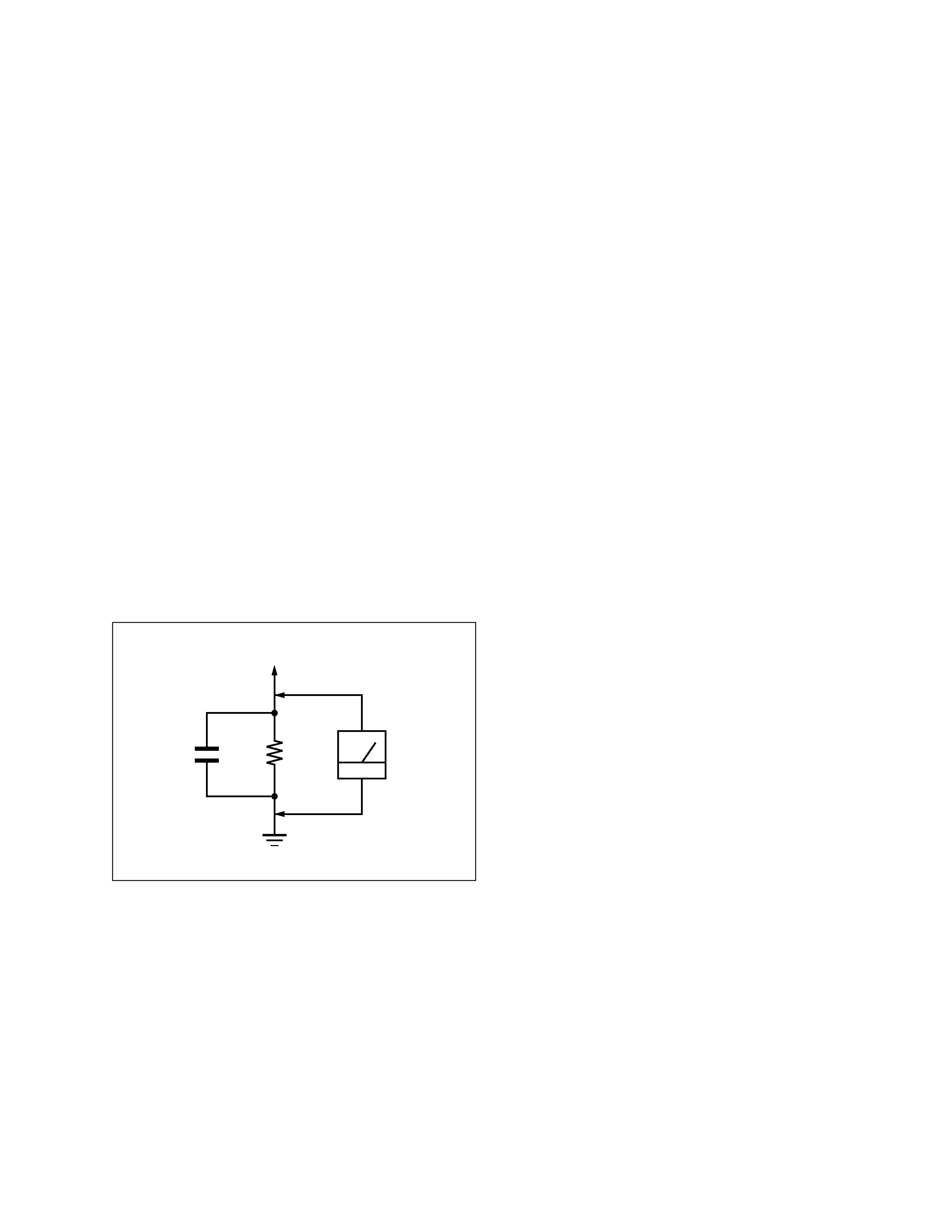
3. Measuring the voltage drop across a resistor by means of a
VOM or battery-operated AC voltmeter. The "limit" indica-
tion is 0.75 V, so analog meters must have an accurate low-
voltage scale. The Simpson 250 and Sanwa SH-63Trd are
examples of a passive VOMs that are suitable. Nearly all
battery operated digital multimeters that have a 2 V AC
range are suitable. (See Fig. A)
WARNING!!
NEVER TURN ON THE POWER IN A CONDITION IN
WHICH THE DEGAUSS COIL HAS BEEN REMOVED.
SAFETY-RELATED COMPONENT WARNING!!
COMPONENTS IDENTIFIED BY SHADING AND MARK
¡ ON THE SCHEMATIC DIAGRAMS, EXPLODED
VIEWS AND IN THE PARTS LIST ARE CRITICAL FOR
SAFE OPERATION. REPLACE THESE COMPONENTS
WITH SONY PARTS WHOSE PART NUMBERS AP-
PEAR AS SHOWN IN THIS MANUAL OR IN SUPPLE-
MENTS PUBLISHED BY SONY. CIRCUIT ADJUST-
MENTS THAT ARE CRITICAL FOR SAFE OPERATION
ARE IDENTIFIED IN THIS MANUAL. FOLLOW THESE
PROCEDURES WHENEVER CRITICAL COMPONENTS
ARE REPLACED OR IMPROPER OPERATION IS SUS-
PECTED.
AVERTISSEMENT!!
NE JAMAIS METTRE SOUS TENSION QUAND LA
BOBINE DE DEMAGNETISATION EST ENLEVÉE.
ATTENTION AUX COMPOSANTS RELATIFS À LA
SÉCURITÉ!!
LES COMPOSANTS IDENTIFIÉS PAR UNE TRAME ET
UNE MARQUE
¡ SONT CRITIQUES POUR LA SÉCURITÉ.
NE LES REMPLACER QUE PAR UNE PIÈCE PORTANT LE
NUMÉRO SPECIFIÉ. LES RÉGLAGES DE CIRCUIT DONT
L'IMPORTANCE EST CRITIQUE POUR LA SÉCURITÉ DU
FONCTIONNEMENT SONT IDENTIFIÉS DANS LE
PRÉSENT MANUEL. SUIVRE CES PROCÉDURES LORS
DE CHAQUE REMPLACEMENT DE COMPOSANTS CRI-
TIQUES, OU LORSQU'UN MAUVAIS FONCTIONNEMENT
EST SUSPECTÉ.
After correcting the original service problem, perform the fol-
lowing safety checks before releasing the set to the customer:
1. Check the area of your repair for unsoldered or poorly-sol-
dered connections. Check the entire board surface for solder
splashes and bridges.
2. Check the interboard wiring to ensure that no wires are
"pinched" or contact high-wattage resistors.
3. Check that all control knobs, shields, covers, ground straps,
and mounting hardware have been replaced. Be absolutely
certain that you have replaced all the insulators.
4. Look for unauthorized replacement parts, particularly tran-
sistors, that were installed during a previous repair. Point
them out to the customer and recommend their replacement.
5. Look for parts which, though functioning, show obvious
signs of deterioration. Point them out to the customer and
recommend their replacement.
6. Check the line cords for cracks and abrasion. Recommend
the replacement of any such line cord to the customer.
7. Check the B+ and HV to see if they are specified values.
Make sure your instruments are accurate; be suspicious of
your HV meter if sets always have low HV.
8. Check the antenna terminals, metal trim, "metallized"
knobs, screws, and all other exposed metal parts for AC
Leakage. Check leakage as described below.
Fig. A. Using an AC voltmeter to check AC leakage.
SAFETY CHECK-OUT
1.5 k
0.15
µF
AC
Voltmeter
(0.75 V)
To Exposed Metal
Parts on Set
Earth Ground

CPD-M151
4
TABLE OF CONTENTS
Section
Title
Page
1. GENERAL .................................................................. 1-1
2. DISASSEMBLY
2-1.
Back Cover Assy Removal ................................. 2-1
2-2.
Cabinet Complete Assy Removal ....................... 2-1
2-3.
A Board, J Board and Inverter Removal ............. 2-2
2-4.
H Board Removal ................................................. 2-2
2-5.
LCD Panel and Lamp Unit Removal ................... 2-3
3. ADJUSTMENTS ...................................................... 3-1
4. DIAGRAMS
4-1.
Block Diagrams .................................................... 4-1
4-2.
Circuit Boards Location ...................................... 4-4
5. EXPLODED VIEWS
5-1.
Chassis ................................................................. 5-1
5-2.
Packing Materials ................................................ 22