TRINITRON® COLOR MONITOR
SERVICE MANUAL
SPECIFICATIONS
17VC CHASSIS
CPD-G220R
US/Canada Model
Chassis No: SCC-L38A-A
CPD-G220S
US/Canada Model
Chassis No: SCC-L38A-A
Design and specifications are subject to change without notice.
CPD-G220R/G220S
Picture tube 0.24 mm aperture grill pitch (center)
17 inches measured diagonally
90-degree deflection
Video image area
(16.1" maximum viewing image)
Approx. 328 X 242 mm (w/h)
(13 x 95/8 inches)
Resolution
Horizontal: Max. 1600 dots
Vertical: Max. 1200 lines
Standard image area
Approx. 312 x 234 mm (w/h)
(123/8 x 91/4 inches)
Input signal
Video
Analog RGB (75 ohms typical)
0.7 Vp-p, ±5%, Positive
Sync
Separate HD/VD,
TTL Polarity Free
External Composite,
TTL Polarity Free (2K ohms impedance)
Sync on Green
Power Consumption
115 W
Deflection frequency
Horizontal: 30 to 85 KHz
Vertical: 48 to 170 Hz
AC input voltage/current 100 to 120 V, 50/60 Hz, 1.7A
220 to 240V, 50/60Hz, 0.9A
Dimensions
402 x 418 x 421 mm (w/h/d)
(157/8 x 161/2 x 165/8 inches)
Mass
Approx. 19 kg (41 lb 14 oz.)
9-978-877-01

-- 2 --
CPD-G220R/G220S
SECTION TITLE
PAGE
Power Management.................................................................................................................................. 3
Self Diagnosis Function ............................................................................................................................ 3
Timing Specification.................................................................................................................................. 3
Safety Check Out Instructions .................................................................................................................. 4
Warnings and Cautions............................................................................................................................. 4
1. Disassembly
1-1. Cabinet Removal ............................................................................................................................... 5
1-2. Service Position................................................................................................................................. 5
1-3. A & D Board Removal........................................................................................................................ 6
1-4. Picture Tube Removal ....................................................................................................................... 7
2. Safety Related Adjustments
2-1. HV Regulator Check.......................................................................................................................... 8
2-2. HV Protector Circuit Check................................................................................................................ 8
2-3. Beam Protector Check (Software Logic) ........................................................................................... 8
2-4. B+ Voltage Check.............................................................................................................................. 8
3. Adjustments
3-1. Landing Rough Adjustment ............................................................................................................... 9
3-2. Landing Fine Adjustment ................................................................................................................... 9
3-3. Convergence Rough Adjustment....................................................................................................... 9
3-4. Convergence and V. Key (H. TRP) Fine Adjustment ......................................................................... 9
3-5. Vertical and Horizontal Position and Size Specification .................................................................. 10
3-6. Focus Adjustment ............................................................................................................................ 10
3-7. Digital Convergence Adjustment ......................................................................................................11
3-8. Convergence Specification...............................................................................................................11
4. Diagrams
4-1. Circuit Boards Location ................................................................................................................... 12
4-2. Schematic Diagrams And Printed Wiring Boards ............................................................................ 12
4-3. Diagrams
Block Diagram................................................................................................................................. 13
A Board - Schematic Diagram......................................................................................................... 15
D Board - Schematic Diagram ........................................................................................................ 17
H1 Board - Schematic Diagram ...................................................................................................... 20
U Board - Schematic Diagram ....................................................................................................... 21
4-4. Semiconductors............................................................................................................................... 22
5. Exploded Views
5-1. Picture Tube .................................................................................................................................... 23
5-2. Chassis............................................................................................................................................ 24
5-2. Packing Materials ............................................................................................................................ 25
6. Electrical Parts List ....................................................................................................................................... 26
TABLE OF CONTENTS
-- 3 --
CPD-G220R/G220S
POWER MANAGEMENT
The power saving mode complies with the VESA Display Power Management Signaling standard. Each state of power management shall be activated
by the host computer terminating the appropriate sync signals. Blanking the video must precede termination of the sync signals. The elapsed time
counter shall also be controlled by the host computer. Reactivation of the monitor shall be accomplished from the host computer by re-establishing the
normal sync signal.
TIMING SPECIFICATION
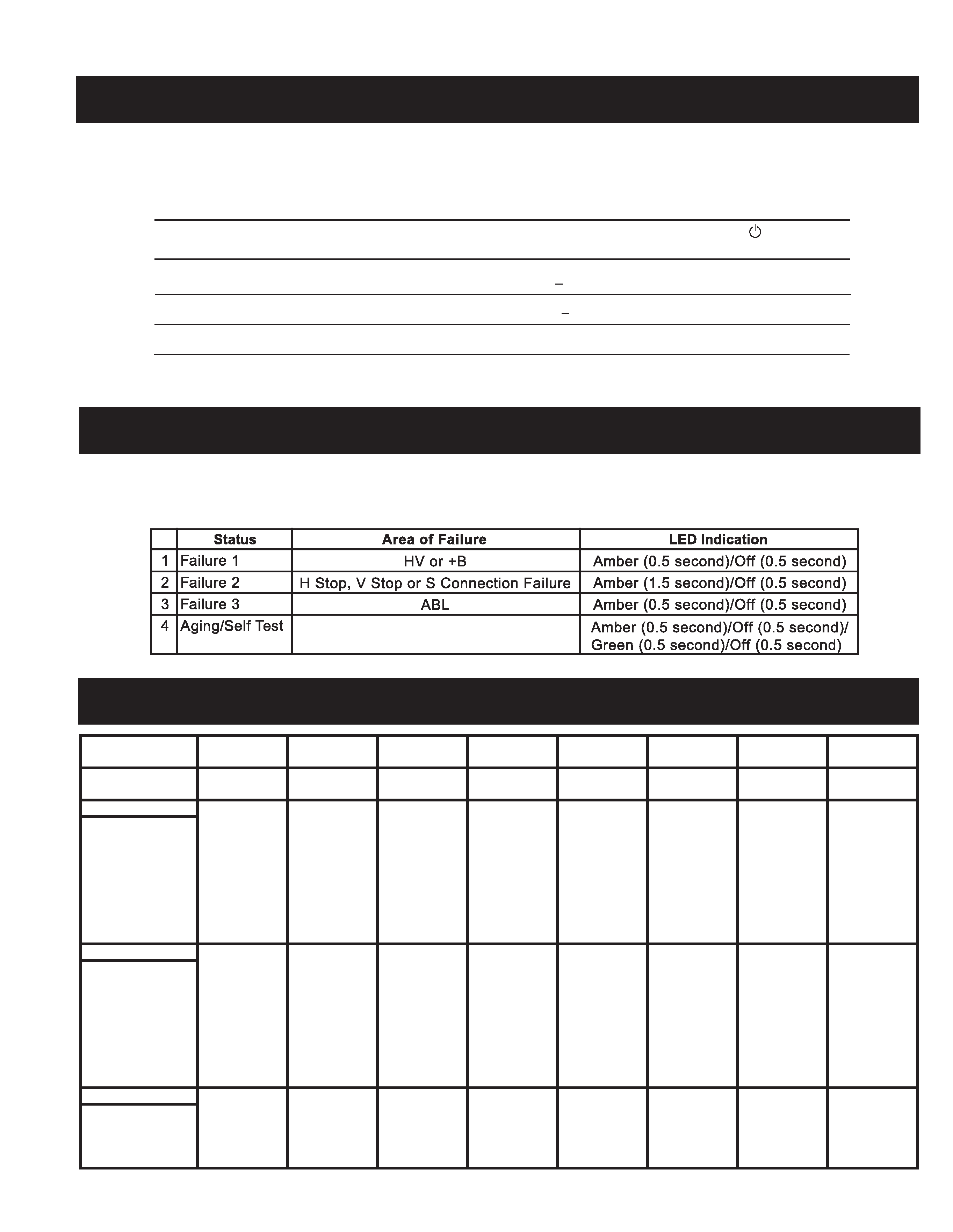
SELF DIAGNOSIS FUNCTION
When a failure occurs, the STANDBY/TIMER lamp will flash a set number of times to indicate the possible cause of the problem. If there is more than
one error, the lamp will identify the first of the problem areas.
Power consumption
Screen
Horizontal
Vertical
Power
Recovery time
indicator
mode
(video)
sync signal sync signal consumption
1
Normal operation
active
yes
yes
< 115 W
--
Green
2
Active-off (3rd mode)
blank
no*
no*
< 3 W
Approx. 10 sec.
Orange
3
Power-off
--
--
--
0 W (approx)
--
Off
* In this mode, the signal will appear in one of three ways: The Horizontal Sync Signal alone off, the Vertical Sync Signal
alone off, or both signals off.
Test Mode
MODE
12345678
Resolution (H x V)
640 X 480
800 X 600
832 X 624
1024 X 768
1024 X 768
720 X 400
640 X 480
1280 X 1024
Dot Clock (MHz)
25.175
56.250
57.238
78.750
94.500
28.322
36.000
135.000
HORIZONTAL
Hor. Freq. (kHz)
31.469
53.674
49.725
60.023
68.677
31.469
43.269
79.976
H-Total
31.778
18.631
20.111
16.660
14.561
31.777
23.111
12.504
H-Blanking
6.356
4.409
5.586
3.657
3.725
6.355
5.333
3.022
H-Front Porch
0.636
0.569
0.559
0.203
0.508
0.636
1.556
0.119
H-Sync.
3.813
1.138
1.117
1.219
1.016
3.813
1.556
1.067
H-Back Porch
1.907
2.702
3.910
2.235
2.201
1.907
2.222
1.837
H-Active
25.422
14.222
14.524
13.003
10.836
25.422
17.778
9.481
(µsec)
VERTICAL
Ver. Freq. (Hz)
59.940
85.061
74.550
75.029
84.997
70.087
85.008
75.025
V-Total
525
631
667
800
808
449
509
1066
V-Blanking
45
31
43
32
40
49
29
42
V-Front Porch
10
1
1
1
1
12
1
1
V-Sync.
2
3
3
3
3233
V-Back Porch
33
27
39
28
36
35
25
38
V-Active
480
600
624
768
768
400
480
1024
(lines)
SYNC.
Int (G)
NO
NO
NO
NO
NO
NO
NO
NO
Ext (H/V)/Polarity
YES -/-
NO +/+
YES -/-
YES +/+
YES +/+
YES -/+
YES -/-
YES +/+
Ext (C/S)/Polarity
NO
NO
NO
NO
NO
NO
NO
NO
Int/Non Int
NON INT
NON INT
NON INT
NON INT
NON INT
NON INT
NON INT
NON INT
-- 4 --
CPD-G220R/G220S
SAFETY CHECK-OUT
After correcting the original service problem, perform the following
safety checks before releasing the set to the customer:
1.
Check the area of your repair for unsoldered or poorly soldered
connections. Check the entire board surface for solder splashes
and bridges.
2.
Check the interboard wiring to ensure that no wires are "pinched" or
touching high-wattage resistors.
3.
Check that all control knobs, shields, covers, ground straps, and
mounting hardware have been replaced. Be absolutely certain that
you have replaced all the insulators.
4.
Look for unauthorized replacement parts, particularly transistors,
that were installed during a previous repair. Point them out to the
customer and recommend their replacement.
5.
Look for parts which, though functioning, show obvious signs of
deterioration. Point them out to the customer and recommend their
replacement.
6.
Check the line cords for cracks and abrasion. Recommend the
replacement of any such line cord to the customer.
7.
Check the B+ and HV to see if they are specified values. Make sure
your instruments are accurate; be suspicious of your HV meter if
sets always have low HV.
8.
Check the antenna terminals, metal trim, "metallized" knobs,
screws, and all other exposed metal parts for AC leakage. Check
leakage as described below.
Leakage Test
The AC leakage from any exposed metal part to earth ground and from
all exposed metal parts to any exposed metal part having a return to
chassis, must not exceed 0.5 mA (500 microamperes). Leakage current
can be measured by any one of three methods.
1.
A commercial leakage tester, such as the Simpson 229 or RCA
WT-540A. Follow the manufacturers' instructions to use these
instructions.
2.
A battery-operated AC milliammeter. The Data Precision 245 digital
multimeter is suitable for this job.
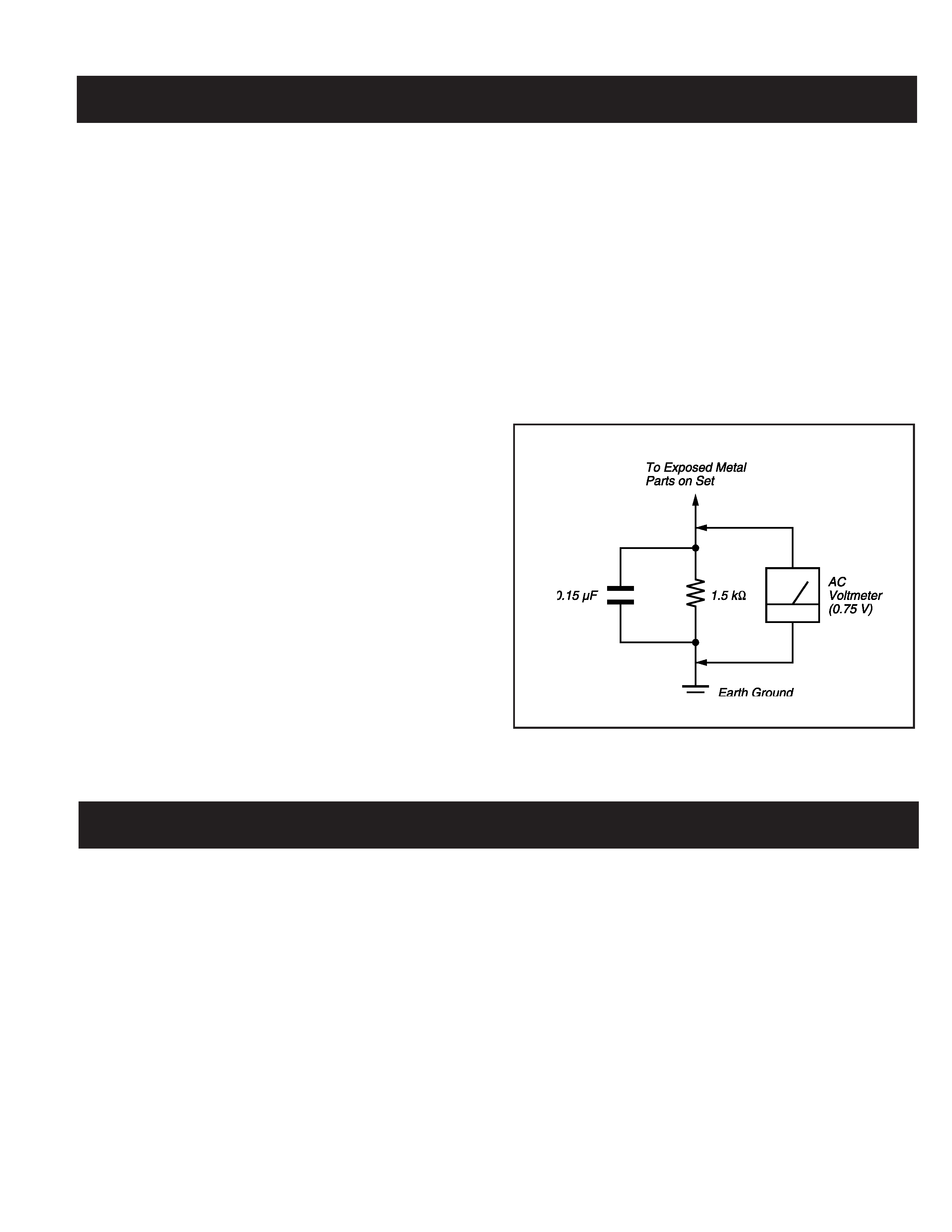
3.
Measuring the voltage drop across a resistor by means of a VOM
or battery-operated AC voltmeter. The "limit" indication is 0.75
V, so analog meters must have an accurate low voltage scale.
The Simpson's 250 and Sanwa SH-63TRD are examples of
passive VOMs that are suitable. Nearly all battery-operated digital
multimeters that have a 2 VAC range are suitable (see Figure A).
Figure A. Using an AC voltmeter to check AC leakage.
WARNINGS AND CAUTIONS
WARNING!!
NEVER TURN ON THE POWER IN A CONDITION IN WHICH THE
DEGAUSS COIL HAS BEEN REMOVED.
SAFETY REALTED COMPONENT WARNING!!
COMPONENTS IDENTIFIED BY SHADING MARK ! ON THE SCHEMATIC
DIAGRAMS, EXPLODED VIEWS AND IN THE PARTS LIST ARE
CRITICAL FOR SAFE OPERATION. REPLACE THESE COMPONENTS
WITH SONY PARTS WHOSE PART NUMBERS APPEAR AS SHOWN IN
THIS MANUAL OR IN SUPPLEMENTS PUBLISHED BY SONY. CIRCUIT
ADJUSTMENTS THAT ARE CRITICAL FOR SAFE OPERATION ARE
IDENTIFIED IN THIS MANUAL.
FOLLOW THESE PROCEDURES
WHENEVER CRITICAL COMPONENTS ARE REPLACED OR
IMPROPER OPERATION IS SUSPECTED.
AVERTISSEMENT!!
NE JAMAIS METTRE SOUS TENSION QUAND LA BOBINE DE
DEMAGNETISATION EST ENLEVEE.
ATTENTION AUX COMPOSANTS RELATIFS A LA SECURITE!!
LES COMPOSANTS IDENTIFIES PAR UNE TRAME ET PAR UNE
MARQUE SUR LES SCHEMAS DE PRINCIPE, LES VUES EXPLOSEES
ET LES LISTES DE PIECES SONT D'UNE IMPORTANCE CRITIQUE
POUR LA SECURITE DU FONCTIONNEMENT. NE LES REMPLACER
QUE PAR DES COMPOSANTS SONY DONT LE NUMERO DE
PIECE EST INDIQUE DANS LE PRESENT MANUEL OU DANS DES
SUPPLEMENTS PUBLIES PAR SONY. LES REGLAGES DE CIRCUIT
DONT L'IMPORTANCE EST CRITIQUE POUR LA SECURITE DU
FONCTIONNEMENT SONT IDENTIFIES DANS LE PRESENT MANUEL.
SUIVRE CES PROCEDURES LORS DE CHAQUE REMPLACEMENT
DE COMPOSANTS CRITIQUES, OU LORSQU'UN MAUVAIS
FONTIONNEMENT SUSPECTE.
-- 5 --
CPD-G220R/G220S
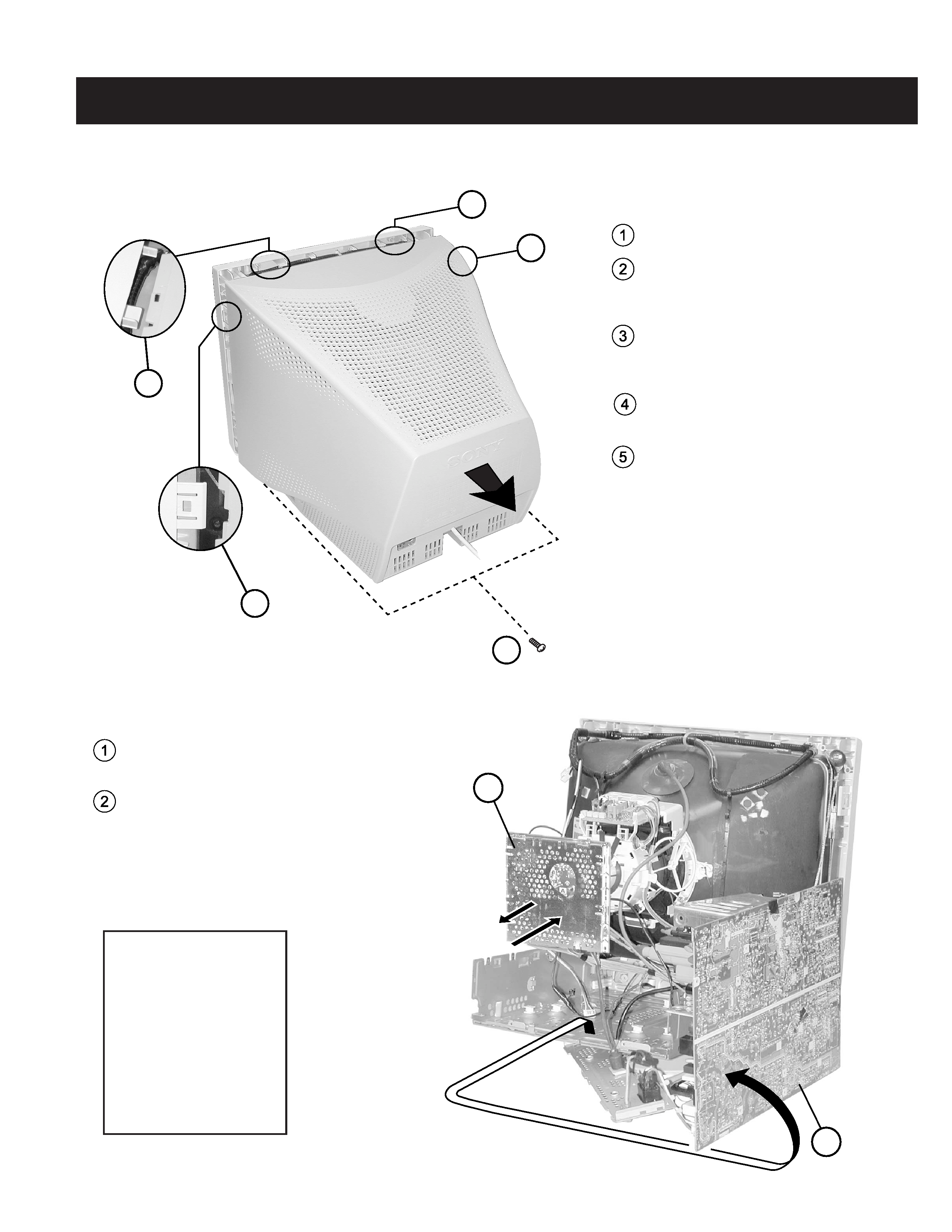
1-1. CABINET REMOVAL
SECTION 1: DISASSEMBLY
1
2
1
2
3
4
5
Remove (2) Screws (+BVTP 4 x 16)
Release side claw - Insert the tip of a flathead
screwdriver approximately 0.25" to unlock the
claw.
Release top claw - Working from the same
side as the the claw in step 2, insert the tip of
a flathead screwdriver to unlock the top claw.
Release top claw - Repeat Step 3 on the
opposite side.
Release side claw - Repeat Step 2 on the
opposite side and gently lift up and then back
to remove the cabinet.
1. When the D-board is placed
in service position, the Safety
Earth Wire (green and yellow
wire) is disconnected.
2. After service is completed and
the D-board reinstalled, the
Safety Earth Wire must be
reattached to the chassis with
the proper screw. This must
be confirmed before any
subsequent procedures are
attempted.
1-2. SERVICE POSITION
Gently wiggle the A board back and forth to unplug
it from the Neck Assembly.
Remove all necessary connections and rotate the D
Board and rest it on its side to expose the bottom.
Be sure to reconnect all wires.