-- 1 --
CPD-EG300
SPECIFICATIONS
D-1H
Picture tube
Video image area
Resolution
Standard image area
I
0.25 mm aperture grill pitch
17 inches measured diagonally
90-degree deflection
(16" maximum viewing image)
Approx. 327 x 243 mm (w/h)
(127/8 x 9 5/8 inches)
Horizontal: Max. 1600 dots
Vertical: Max. 1200 lines
Approx. 312 x 234 mm (w/h)
(12 3/8 x 9 1/4 inches)
Deflection frequency
AC input voltage / current
Dimensions
Mass
CHASSIS
Horizontal: 31.0 to 85 KHz
Vertical: 50 to120 Hz
100 to 120 V, 50/60 Hz, 1.8 A
220 to 240V, 50/60Hz, 1A
406 x 432 x 420 mm (w/h/d)
(16 x 17 1/8 x 16 5/8 inches)
Approx. 18.0 kg (39 lb 11 oz)
SERVICE MANUAL
Design and specifications are subject to change without notice.
CPD-EG300
VIDEO DISPLAY
CPD-EG300
US Model
Canadian Model
AEP Model
S. Hemisphere Model
Chassis No. SCC-L07J-A
-- 2 --
CPD-EG300
POWER SAVING FUNCTION
This monitor is equipped with a power saving function. It goes
into power-saving mode if either of the following conditions
exist:
If either the horizontal sync or vertical sync are not present,
the monitor goes into suspend mode. Suspend mode means
that the power-saving level is substantial, yet the monitor
recovers relatively fast when you press a key or touch the
mouse.
If both horizontal sync and vertical sync are not present, the
monitor goes into active-off mode. Active-off mode means
that the power-saving level is almost at the level of being
shut off, and the monitor takes several seconds to recover
when you press a key or touch the mouse.
NOTE:
TIMING SPECIFICATION
The Power Saving function automatically
places the monitor into active-off state if
you turn on the power switch and leave the
rest of the system off. However, once the
monitor can sense the horizontal and verti-
cal syncs, it automatically returns to its nor-
mal operation state.
State
Power Used
Resume Time
Power Indicator
Power Saving Indicator
1
Normal
100%
none
green LED on
off
2
Suspend
approx. 10%
approx. 3 sec.
green LED on
orange LED on
3
Active-off
approx. 7%
approx. 10 sec.
off
orange LED on
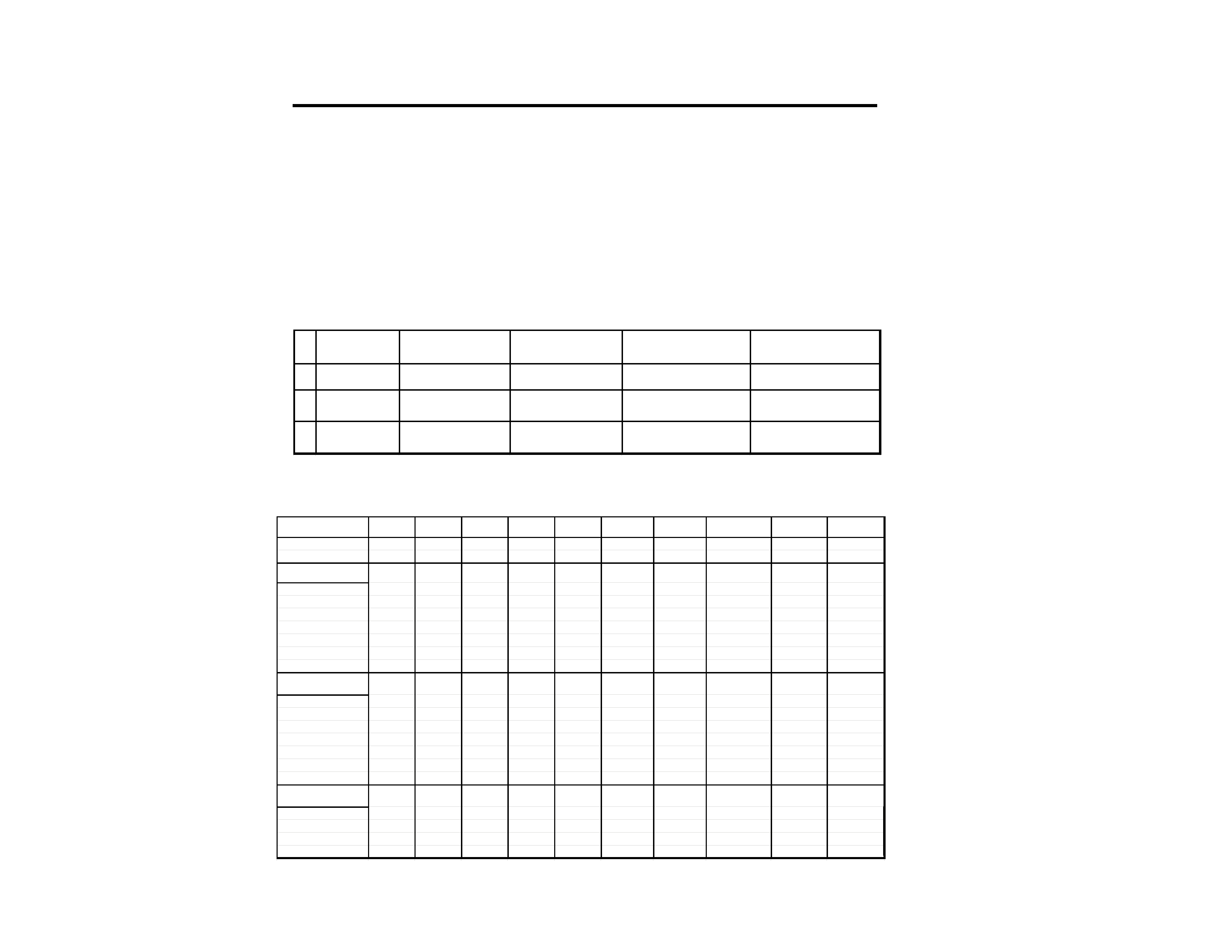
MODE
12345
6
7
Primary Mode
89
1 0
Resolution (H x V)
640x480 640X480 720X400 800x600 800x600 1024x768 1024x768 1280x1024
1600x1200 1600x1200
Dot Clock (MHz)
25.175
36.000
28.322
40.000
56.250
65.000
94.500
135.000
158.400
173.000
HORIZONTAL
Hor. Freq. (kHz)
31.469
43.269
31.469
37.879
53.674
48.363
68.677
79.976
75.000
81.913
H-Total
31.778
23.111
31.777
26.400
18.631
20.677
14.561
12.504
13.333
12.208
H-Blanking
6.356
5.333
6.355
6.400
4.409
4.923
3.725
3.022
3.232
2.960
H-Front Porch
0.636
1.556
0.636
1.000
0.569
0.369
0.508
0.119
0.404
0.370
H-Sync.
3.813
1.556
3.813
3.200
1.138
2.092
1.016
1.067
1.212
1.110
H-Back Porch
1.907
2.222
1.907
2.200
2.702
2.462
2.201
1.837
1.616
1.480
H-Active (
µsec)
25.422
17.778
25.422
20.000
14.222
15.754
10.836
9.481
10.101
9.249
VERTICAL
Ver. Freq. (Hz)
59.940
85.008
70.087
60.317
85.061
60.004
84.997
75.025
60.000
65.530
V-Total
5 2 5
5 0 9
4 4 9
6 2 8
6 3 1
8 0 6
8 0 8
1066
1250
1250
V- Blanking
4 5
2 9
4 9
2 8
3 1
3 8
4 0
4 2
5 0
5 0
V-Front Porch
1 0
1
1 2
1
1
3
1
1
1
1
V-Sync.
23243
6
3
3
3
3
V- Back Porch
3 3
2 5
3 5
2 3
2 7
2 9
3 6
3 8
4 6
4 6
V-Active (lines)
4 8 0
4 8 0
4 0 0
6 0 0
6 0 0
7 6 8
7 6 8
1024
1200
1200
SYNC.
Int(G)
NO
NO
NO
NO
NO
NO
NO
NO
NO
NO
Ext(H/V)/Polarity
YES -/-
YES -/-
YES -/+
YES +/+
YES +/+
YES -/-
YES +/+
YES +/+
YES +/+
YES +/+
Ext (CS)/Polarity
NO
NO
NO
NO
NO
NO
NO
NO
NO
NO
Int/Non Int
Non Int
Non Int
Non Int
Non Int
Non Int
Non Int
Non Int
Non Int
Non Int
Non Int
-- 3 --
CPD-EG300
1.5 k W
0.15 µF
AC
Voltmeter
(0.75 V)
To Exposed Metal
Parts on Set
Earth Ground
SAFETY CHECK-OUT
(US Model only)
After correcting the original service problem, perform
the following safety checks before releasing the set to the
customer:
LEAKAGE TEST
The AC leakage from any exposed metal part to earth ground
and from all exposed metal parts to any exposed metal part having
a return to chassis, must not exceed 0.5 mA (500 microampere).
Leakage current can be measured by any one of three methods.
WARNING!!
NEVER TURN ON THE POWER IN A CONDITION IN WHICH THE
DEGAUSS COIL HAS BEEN REMOVED.
SAFETY-RELATED COMPONENT WARNING!!
COMPONENTS IDENTIFIED BY SHADING AND MARK
¡ ON
THE SCHEMATIC DIAGRAMS, EXPLODED VIEWS AND IN THE
PARTS LIST ARE CRITICAL FOR SAFE OPERATION. REPLACE
THESE COMPONENTS WITH SONY PARTS WHOSE PART
NUMBERS APPEAR AS SHOWN IN THIS MANUAL OR IN
SUPPLEMENTS PUBLISHED BY SONY. CIRCUIT ADJUSTMENTS
THAT ARE CRITICAL FOR SAFE OPERATION ARE IDENTIFIED
IN THIS MANUAL. FOLLOW THESE PROCEDURES WHENEVER
CRITICAL COMPONENTS ARE REPLACED OR IMPROPER
OPERATION IS SUSPECTED.
AVERTISSEMENT!!
NE JAMAIS METTRE SOUS TENSION QUAND LA BOBINE DE
DEMAGNETISATION EST ENLEVEE.
ATTENTION AUX COMPOSANTS RELATIFS A LA
SECURITE!!
LES COMPOSANTS IDENTIFIES PAR UNE TRAME ET PAR UNE
MARQUE
¡ SUR LES SCHEMAS DE PRINCIPE, LES VUES
EXPLOSEES ET LES LISTES DE PIECES SONT D'UNE
IMPORTANCE
CRITIQUE
POUR
LA
SECURITE
DU
FONCTIONNEMENT. NE LES REMPLACER QUE PAR DES
COMPOSANTS SONY DONT LE NUMERO DE PIECE EST
INDIQUE DANS LE PRESENT MANUEL OU DANS DES SUPPLE-
MENTS PUBLIES PAR SONY. LES REGLAGES DE CIRCUIT
DONT
L'IMPORTANCE
EST
CRITIQUE
POUR
LA
SECURITE DU FONCTIONNEMENT SONT IDENTIFIES DANS
LE PRESENT MANUEL. SUIVRE CES PROCEDURES LORS DE
CHAQUE REMPLACEMENT DE COMPOSANTS CRITIQUES, OU
LORSQU'UN MAUVAIS FONTIONNEMENT SUSPECTE.
1. Check the area of your repair for unsoldered or
poorly-soldered connections. Check the entire board
surface
for
solder
splashes
and
bridges.
2. Check the interboard wiring to ensure that no wires
are "pinched" or contact high-wattage resistors.
3. Check that all control knobs, shields, covers, ground
straps, and mounting hardware have been replaced.
Be absolutely certain that you have replaced all the
insulators.
4. Look for unauthorized r eplacement parts,
particularly transistors, that were installed during
a previous repair. Point them out to the customer
and recommend their replacement.
5. Look for parts which, though functioning, show
obvious signs of deterioration. Point them out to
the customer and recommend their replacement.
6. Check the line cords for cracks and abrasion.
Recommend the replacement of any such line cord
to the customer.
7. Check the B+ and HV to see if they are specified
values. Make sure your instruments are accurate;
be suspicious of your HV meter if sets always have
low HV.
8. Check the antenna terminals, metal trim,
"metallized" knobs, screws, and all other exposed
metal parts for AC Leakage. Check leakage as
described below.
1. A commercial leakage tester, such as the Simpson 229 or
RCA WT-540A. Follow the manufacturers' instructions to
use these instructions.
2. A battery-operated AC milliammeter. The Data Precision
245 digital multimeter is suitable for this job.
3. Measuring the voltage drop across a resistor by means of
a VOM or battery-operated AC voltmeter. The "limit"
indication is 0.75 V, so analog meters must have an accurate
low voltage scale. The Simpson's 250 and Sanwa
SH-63Trd are examples of passive VOMs that are suitable.
Nearly all battery operated digital multimeters that have a
2V AC range are suitable. (See Fig. A)

-- 4 --
CPD-EG300
TABLE OF CONTENTS
Section
Title
Page
1. GENERAL ................................................................................... 5
2. DISASSEMBLY
2-1. Cabinet Removal ............................................................9
2-2. Service Position .............................................................. 9
2-3. D and A Board Removal................................................ 9
2-4. Picture Tube Removal ................................................... 10
3. SAFETY RELATED ADJUSTMENT................................. 11
4. ADJUSTMENTS ........................................................................ 12
5. DIAGRAMS
5-1. Block Diagram ................................................................15
5-2. Circuit Boards Location ................................................. 18
5-3. Schematic Diagrams and Printed Wiring Boards ...... 18
1. D Board - Schematic Diagram ................................. 19
2. A Board - Schematic Diagram ................................. 23
5-4. Semiconductors ..............................................................27
6. EXPLODED VIEWS
6-1. Chassis ........................................................................... 29
6-2. Packing Materials .......................................................... 30
7. ELECTRICAL PARTS LIST ................................................ 31
--
5
--
CPD-EG300
SECTION 1
GENERAL
The instructions given here are partial abstracts from the Operating Instruction Manual. The page numbers shown reflect those of the Operating Instruction Manual.
Connecting the Monitor
11
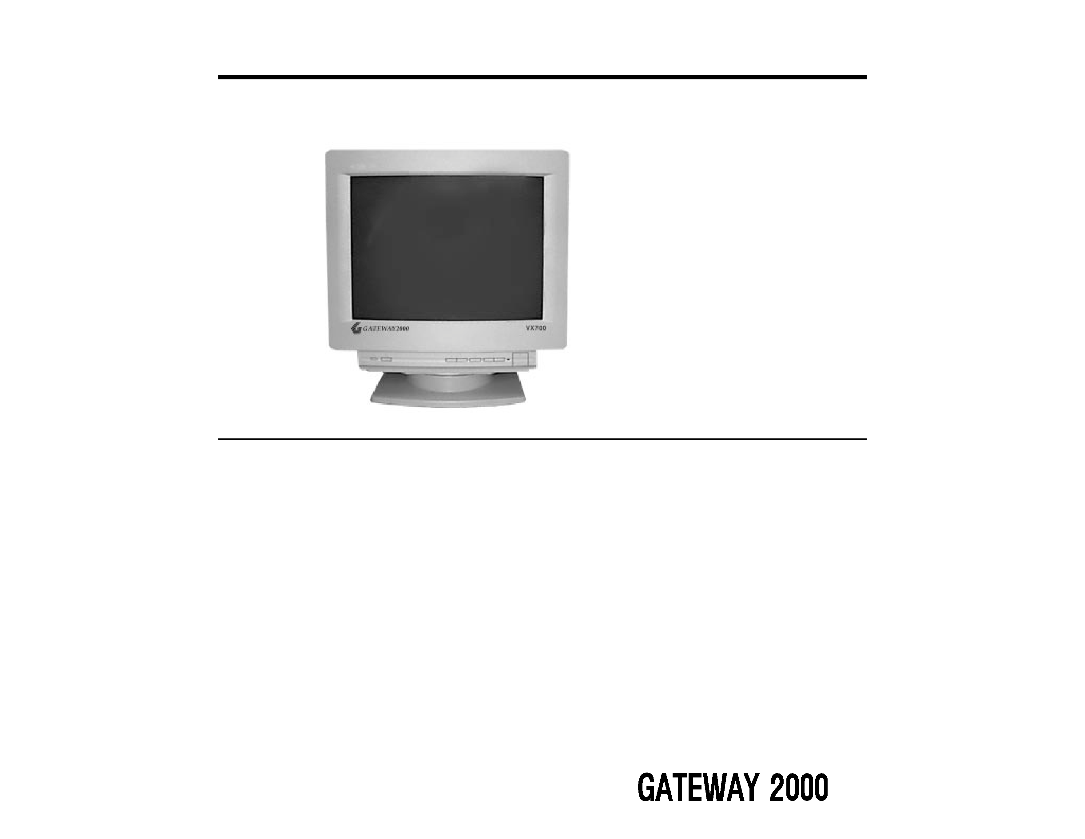
To set up the VX700:
1.
2.
3.
1.
2.
12
VX700 User's Guide
To use your VX700:
1.
2.
Operating the Monitor
13