SERVICE MANUAL
19VC CHASSIS
Design and specifications are subject to change without notice.
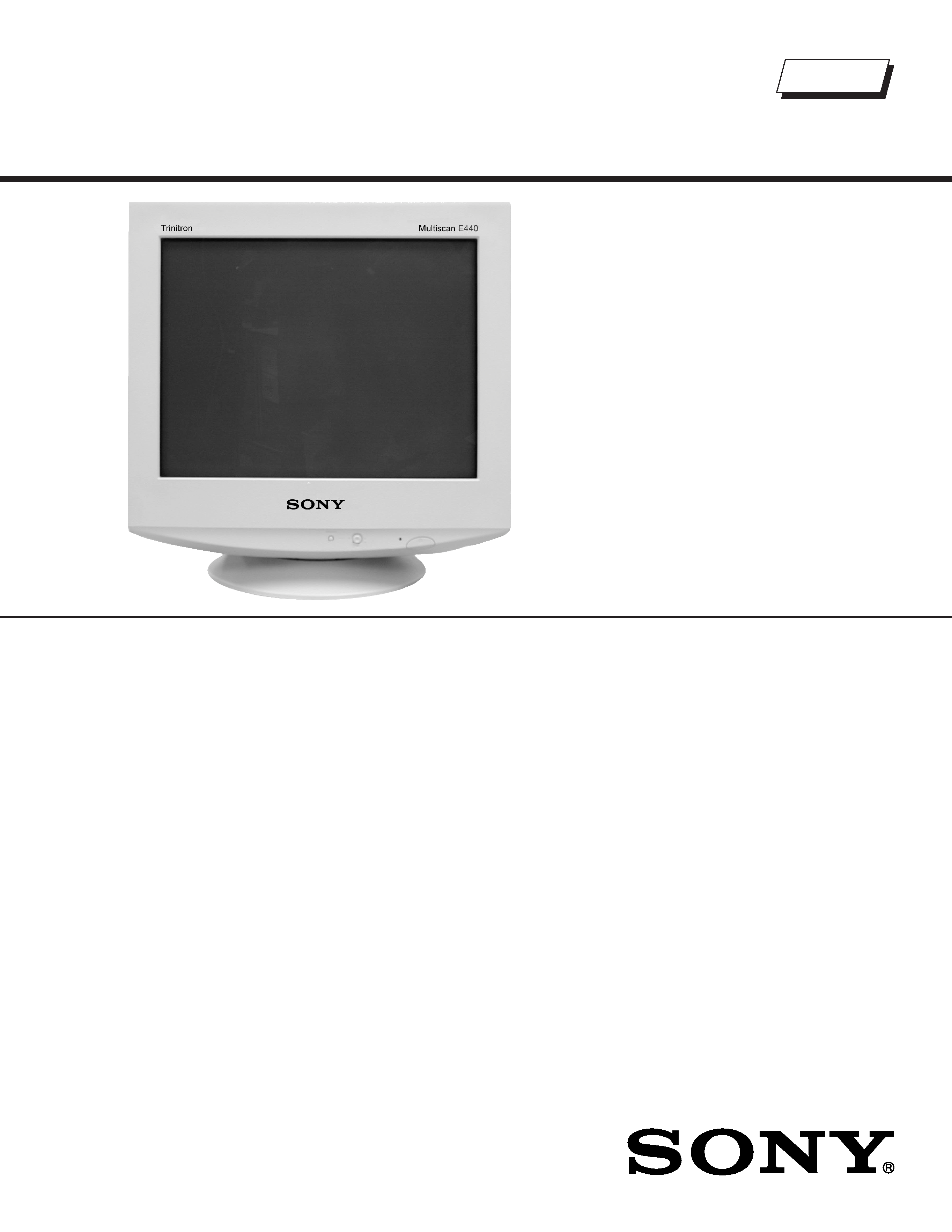
TRINITRON
® COLOR MONITOR
US/Canada Model
Chassis No: SCC-L38L-A
CPD-E440
9-978-886-01
ORIGINAL MANUAL ISSUE DATE: 6/2002
ALL REVISIONS AND UPDATES TO THE ORIGINAL MANUAL ARE APPENDED TO THE END OF THE PDF FILE.
REVISION DATE
REVISION TYPE
SUBJECT
6/2002
No revisions or updates are applicable at this time.
HISTORY INFORMATION FOR THE FOLLOWING MANUAL:
SERVICE MANUAL
19VC CHASSIS
Design and specifications are subject to change without notice.
TRINITRON
® COLOR MONITOR
US/Canada Model
Chassis No: SCC-L38L-A
CPD-E440
9-978-886-01
Picture tube
0.24 mm aperture grill pitch (center)
19 inches measured diagonally
90-degree deflection
FD Trinitron
Video image area
Approx. 365 X 274 mm (w/h)
(14 3/8 x 10 7/8 inches)
Viewing Image
Approx. 456 mm
(18 inches)
Resolution
Maximum
Horizontal: 1920 dots
Vertical: 1440 lines
Recommended
Horizontal: 1280 dots
Vertical: 1024 lines
Standard image area
Approx. 352 x 264 mm (w/h)
(13 7/8 x 10 3/4 inches)
Input signal
Video
Analog RGB (75 ohms typical)
0.7 Vp-p, ±5%, Positive
Sync
Separate HD/VD,
TTL Polarity Free
External Composite,
TTL Polarity Free (2K ohms impedance)
Sync on Green
Power Consumption
130 W
Deflection frequency
Horizontal: 30 to 96 KHz
Vertical: 48 to 170 Hz
AC input voltage/current
100 to 240V, 50/60 Hz, Max. 2.0A
Dimensions
461 x 479 x 470 mm (w/h/d)
(18 1/8 x 19 1/8 x 18 1/2 inches)
Mass
Approx. 26 kg (57 lbs)
Supplied Accessories
Power Cord (1)
Warranty Card (1)
Instruction Manual (1)
SPECIFICATIONS
Self Diagnosis
Supported model

-- 3 --
CPD-E440
SECTION TITLE
PAGE
Power Management.................................................................................................................................. 4
Self Diagnosis Function ............................................................................................................................ 4
Timing Specification.................................................................................................................................. 4
Warnings and Cautions............................................................................................................................. 5
Safety Check-Out ..................................................................................................................................... 6
1. Disassembly
1-1. Cabinet Removal ............................................................................................................................... 7
1-2. Service Position................................................................................................................................. 7
1-3. A and D Board Removal .................................................................................................................... 8
1-4. Picture Tube Removal ....................................................................................................................... 9
Anode Cap Removal ......................................................................................................................... 9
2. Safety Related Adjustments
2-1. HV Regulator Check........................................................................................................................ 10
2-2. HV Protector Circuit Check.............................................................................................................. 10
2-3. Beam Protector Check (Software Logic) ......................................................................................... 10
2-4. B+ Voltage Check ............................................................................................................................ 10
3. Adjustments
3-1. Landing Rough Adjustment ..............................................................................................................11
3-2. Landing Fine Adjustment ..................................................................................................................11
3-3. Convergence Rough Adjustment..................................................................................................... 12
3-4. Convergence Adjustment <Static Convergence>............................................................................ 12
3-5. Vertical and Horizontal Position and Size Specification .................................................................. 13
3-6. Focus Rough Adjustment ................................................................................................................ 13
3-7. Convergence Specification.............................................................................................................. 13
3-8. White Balance Adjustment Specification ......................................................................................... 13
4. Diagrams
4-1. Circuit Boards Location ................................................................................................................... 14
4-2. Printed Wiring Boards And Schematic Diagram Information ........................................................... 14
4-3. Block Diagrams ............................................................................................................................... 15
4-4. Schematics and Supporting Information ......................................................................................... 17
A Board - Schematic Diagram......................................................................................................... 17
D Board - Schematic Diagram ........................................................................................................ 19
L Board - Schematic Diagram ......................................................................................................... 22
H Board - Schematic Diagram ........................................................................................................ 23
4-5. Semiconductors............................................................................................................................... 24
5. Exploded Views
5-1. Picture Tube .................................................................................................................................... 26
5-2. Chassis............................................................................................................................................ 27
5-3. Packing Materials ............................................................................................................................ 28
6. Electrical Parts List ....................................................................................................................................... 29
TABLE OF CONTENTS
-- 4 --
CPD-E440
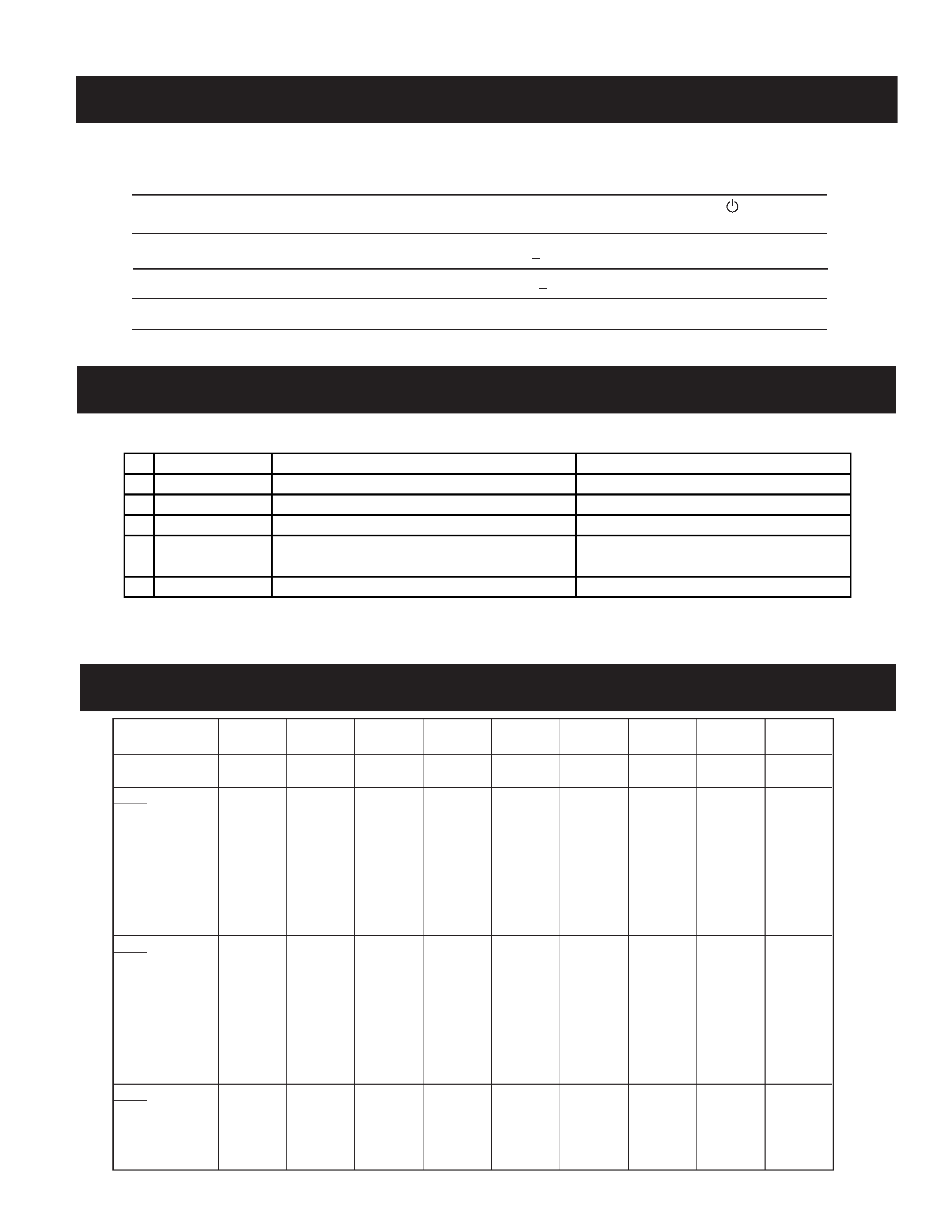
POWER MANAGEMENT
The power saving mode complies with the VESA Display Power Management Signaling standard. Each state of power management shall be
activated by the host computer terminating the appropriate sync signals. Blanking the video must precede termination of the sync signals. The
elapsed time counter shall also be controlled by the host computer. Reactivation of the monitor shall be accomplished from the host computer by
re-establishing the normal sync signal.
TIMING SPECIFICATION
SELF DIAGNOSIS FUNCTION
When a failure occurs, the STANDBY/TIMER lamp will flash a set number of times to indicate the possible cause of the problem. If there is more
than one error, the lamp will identify the first of the problem areas.
Status
Area of Failure
LED Indication
1
Failure 1
HV or +B
Amber (0.5 second)/Off (0.5 second)
2
Failure 2
H Stop, V Stop or S Connection Failure
Amber (1.5 second)/Off (0.5 second)
3
Failure 3
ABL Protector
Amber (0.5 second)/Off (1.5 second)
4
Aging/Self Test
Amber (0.5 second)/Off (0.5 second)/
Green (0.5 second)/Off (0.5 second)
5
Out of Scan Range
Green (OSD indication)
Aging Mode (Video Aging)
:
During Power Save, press MENU button for longer than 2 seconds.
Monitor Information and RGB bar :
During Power Save, press CONT+ button for longer than 2 seconds.
ALL White
:
During Power Save, press CONT- button for longer than 2 seconds.
MODE
Primary Mode
MODE AT PRODUCTION
MODE 1
MODE 2
MODE 3
MODE 4
MODE 5
MODE 6
MODE 7
MODE 8
MODE 9
RESOLUTION
640 X 480
800 X 600
832 X 624
1280 X 1024
1024 X 768
720 X 400
640 X 480
1600 X 1200
1152 X 870
CLOCK
25.175 MHz
56.250 MHz
57.283 MHz
157.500 MHz
94.500 MHz
28.322 MHz
36.000 MHz
202.500 MHz
100.000 MHz
-- HORIZONTAL --
H-FREQ
31.469 kHz
53.674 kHz
49.725 kHz
91.146 kHz
68.677 kHz
31.469 kHz
43.269 kHz
93.750 kHz
68.681 kHz
µsec
µsec
µsec
µsec
µsec
µsec
µsec
µsec
µsec
H. TOTAL
31.778
18.631
20.111
10.971
14.561
31.777
23.111
10.667
14.560
H. BLK
6.356
4.409
5.586
2.844
3.725
6.355
5.333
2.765
3.040
H. FP
0.636
0.569
0.559
0.406
0.508
0.636
1.556
0.316
0.320
H. SYNC
3.813
1.138
1.117
1.016
1.016
3.813
1.556
0.948
1.280
H. BP
1.907
2.702
3.910
1.422
2.201
1.907
2.222
1.501
1.440
H. ACTIV
25.422
14.222
14.524
8.127
10.836
25.422
17.778
7.901
11.520
-- VERTICAL --
V. FREQ (HZ)
59.940 Hz
85.061 Hz
74.550 Hz
85.024 Hz
84.997 Hz
70.087 Hz
85.008 Hz
75.000 Hz
75.062 Hz
lines
lines
lines
lines
lines
lines
lines
lines
lines
V. TOTAL
525
631
667
1072
808
449
509
1250
915
V. BLK
45
31
43
48
40
49
29
50
45
V. FP
10
1
1
1
1
12
1
1
3
V. SYNC
23
33
32
3
3
3
V. BP
33
27
39
44
36
35
25
46
39
V. ACTIV
480
600
624
1024
768
400
480
1200
870
-- SYNC --
INT(G)
NO
NO
NO
NO
NO
NO
NO
NO
NO
EXT (H/V) /POLARITY
YES N/N
NO P/P
YES N/N
YES P/P
YES P/P
YES N/P
YES N/N
YES P/P
YES N/N
EXT (CS) /POLARITY
NO
NO
NO
NO
NO
NO
NO
NO
NO
INT/NON INT
NON INT
NON INT
NON INT
NON INT
NON INT
NON INT
NON INT
NON INT
NON INT
Power consumption
Screen
Horizontal
Vertical
Power
Recovery time
indicator
mode
(video)
sync signal sync signal consumption
1
Normal operation
active
yes
yes
< 130 W
--
Green
2
Active-off (3rd mode)
blank
no*
no*
< 3 W
Approx. 10 sec.
Orange
3
Power-off
--
--
--
0 W (approx)
--
Off
* In this mode, the signal will appear in one of three ways: The Horizontal Sync Signal alone off, the Vertical Sync Signal
alone off, or both signals off.

-- 5 --
CPD-E440
WARNINGS AND CAUTIONS
CAUTION
Short circuit the anode of the picture tube and the anode cap to the metal chassis, CRT shield, or carbon painted on the CRT, after
removing the anode.
WARNING!!
An isolation transformer should be used during any service to avoid possible shock hazard, because of live chassis. The chassis of this
receiver is directly connected to the ac power line.
! SAFETY-RELATED COMPONENT WARNING!!
Components identified by shading and ! mark on the schematic diagrams, exploded views, and in the parts list are critical for safe
operation. Replace these components with Sony parts whose part numbers appear as shown in this manual or in supplements published
by Sony. Circuit adjustments that are critical for safe operation are identified in this manual. Follow these procedures whenever critical
components are replaced or improper operation is suspected.
ATTENTION!!
Apres avoir deconnecte le cap de l'anode, court-circuiter l'anode du tube cathodique et celui de l'anode du cap au chassis metallique de
l'appareil, ou la couche de carbone peinte sur le tube cathodique ou au blindage du tube cathodique.
Afin d'eviter tout risque d'electrocution provenant d'un chássis sous tension, un transformateur d'isolement doit etre utilisé lors de tout
dépannage. Le chássis de ce récepteur est directement raccordé à l'alimentation du secteur.
! ATTENTION AUX COMPOSANTS RELATIFS A LA SECURITE!!
Les composants identifies par une trame et par une marque ! sur les schemas de principe, les vues explosees et les listes de pieces
sont d'une importance critique pour la securite du fonctionnement. Ne les remplacer que par des composants Sony dont le numero de
piece est indique dans le present manuel ou dans des supplements publies par Sony. Les reglages de circuit dont l'importance est
critique pour la securite du fonctionnement sont identifies dans le present manuel. Suivre ces procedures lors de chaque remplacement
de composants critiques, ou lorsqu'un mauvais fonctionnement suspecte.