-- 1 --
CPD-220GS
SPECIFICATIONS
Picture tube
Viewable image size
Resolution
Standard image area
0.25 mm aperture grill pitch
17 inches measured diagonally
90-degree deflection
Approx. 327 x 243 mm (w/h)
(12 7/8 x 9 5/8 inches)
16.0" viewing image
Horizontal: Max. 1280 dots
Vertical: Max. 1024 lines
Approx. 312 x 234 mm (w/h)
(12 3/8 x 9 1/4inches)
Deflection frequency
Plug & Play
Speaker
Headphones output
Audio input
AC input voltage / current
Power consumption
Dimensions
Mass
Horizontal: 30 to 85 KHz
Vertical: 48 to120 Hz
DDC1/2B/2Bi, GTF
0.25W (monaural)
Stereo minijack, accepts impedance
of 8
or more
Stereo minijack
100 to 240 V, 50-60 Hz, 1.9 - 1.1 A
Max. 120W
406 x 432 x 420 mm (w/h/d)
(16 x 171/8 x 165/8 inches)
Approx. 18.0 kg (39 lb 11 oz)
SERVICE MANUAL
Design and specifications are subject to change without notice.
CPD-220GS
COLOR COMPUTER DISPLAY
CPD-220GS
US Model
Canadian Model
Chassis No. SCC-L23A-A
D-1H Plus CHASSIS
-- 2 --
CPD-220GS
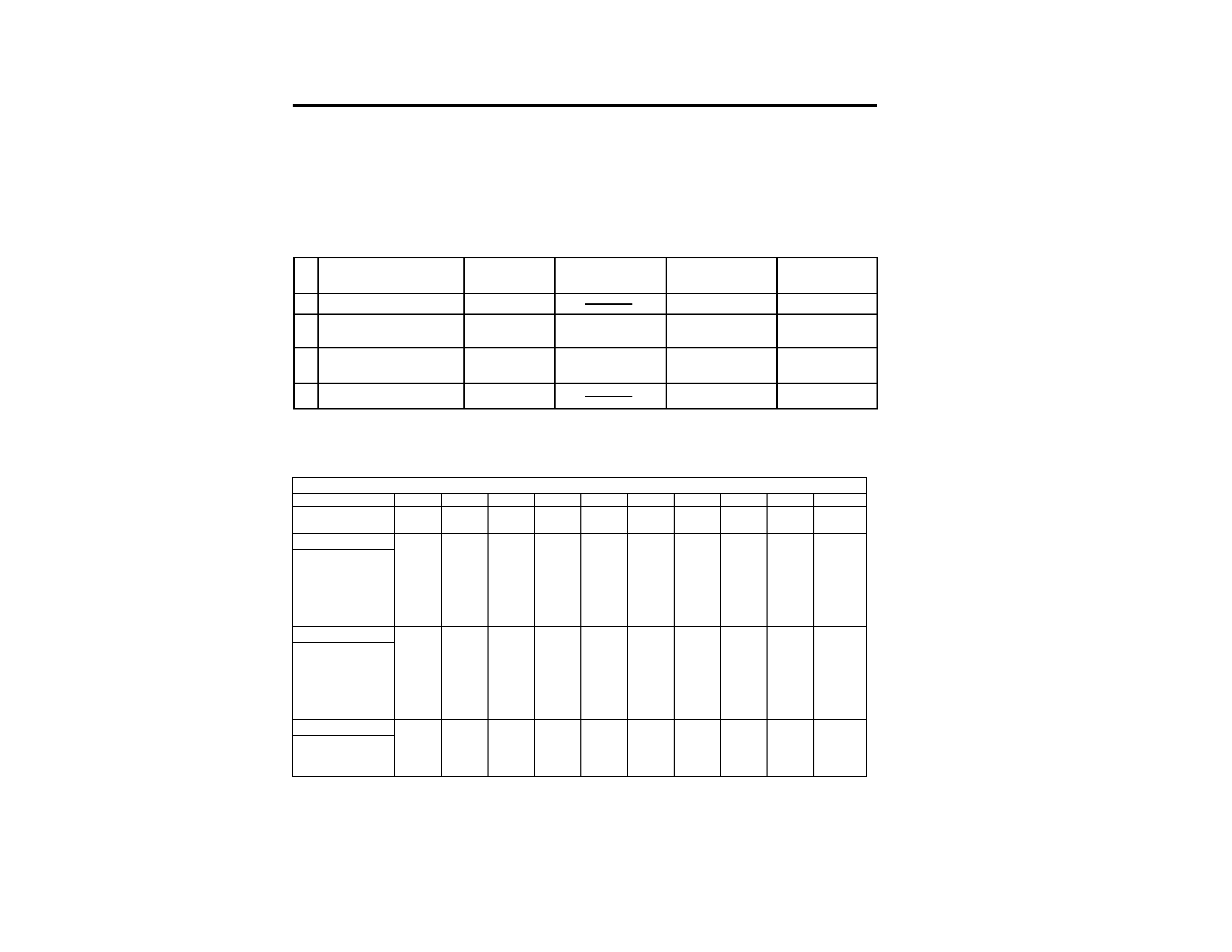
State
Power
Required
u Power indicator
POWER SAVING
consumption
resumption time
indicator
POWER SAVING FUNCTION
This monitor meets the power saving guidelines set
by the EPA Energy Star Program as well as the more
stringent TC092 guidelines (NUTEK). It is capable of
reduced power consumption when used with a com-
puter equipped with Display Power Management Sig-
naling (DPMS). By sensing the absence of the sync
signal coming from the computer, it will reduce the
power consumption as follows:
approx. 7%
approx. 15 sec.
off
orange on
approx. 13%
approx. 5 sec.
green on
orange on
Active-off
(2nd step of power saving)
Suspend
(1st step of power saving)
Normal Operation
100%
green on
off
Power - Off
0%
off
off
1
2
3
4
The Power Saving function will automati-
cally put the monitor into Active-off state
if the power switch is turned on without
any video signal input. Once the horizon-
tal and vertical syncs are sensed, the moni-
tor will automatically return to its Normal
operation state.
CAUTION:
TIMING SPECIFICATION
MODE
123456789
1 0
Resolution (H x V)
640 x 480
640 x 480
720 x 400
800 x 600
800 x 600
832 x 624 1024 x 768 1024 x 768 1024 x 768 1280 x 1024
Dot Clock (MHz)
25.175
36.000
28.322
49.500
56.250
57.283
78.750
80.000
94.500
135.000
HORIZONTAL
Hor. Freq. (kHz)
31.469
43.269
31.469
46.875
53.674
49.725
60.024
60.241
68.677
79.976
H-Total
31.778
23.111
31.777
21.333
18.631
20.111
16.660
16.600
14.561
12.504
H-Blanking
6.356
5.333
6.355
5.172
4.409
5.586
3.657
3.800
3.725
3.022
H-Front Porch
0.636
1.556
0.636
0.323
0.569
0.559
0.203
0.400
0.508
0.119
H-Sync.
3.813
1.556
3.813
1.616
1.138
1.117
1.219
1.200
1.016
1.067
H-Back Porch
1.907
2.222
1.907
3.232
2.702
3.910
2.235
2.200
2.201
1.837
H-Active
25.422
17.778
25.422
16.162
14.222
14.524
13.003
12.800
10.836
9.481
(
µsec)
VERTICAL
Ver. Freq. (Hz)
59.940
85.008
70.087
75.000
85.061
74.550
75.030
74.927
84.997
75.025
V-Total
5 2 5
5 0 9
4 4 9
6 2 5
6 3 1
6 6 7
8 0 0
8 0 4
8 0 8
1066
V-Blanking
4 5
2 9
4 9
2 5
3 1
4 3
3 2
3 6
4 0
4 2
V-Front Porch
1 0
1
1 2
111131
1
V-Sync.
232333333
3
V-Back Porch
3 3
2 5
3 5
2 1
2 7
3 9
2 8
3 0
3 6
3 8
V-Active
4 8 0
4 8 0
4 0 0
6 0 0
6 0 0
6 2 4
7 6 8
7 6 8
7 6 8
1024
(lines)
SYNC.
Int (G)
No
No
No
No
No
No
No
No
No
No
Ext
(H/V)/Polarity
Yes -/-
Yes -/-
Yes -/+
Yes +/+
Yes +/+
Yes -/-
Yes +/+
Yes -/-
Yes +/+
Yes +/+
Ext (CS)/Polarity
No
No
No
No
No
No
No
No
No
No
Int/Non Int
Non Int
Non Int
Non Int
Non Int
Non Int
Non Int
Non Int
Non Int
Non Int
Non Int
-- 3 --
CPD-220GS
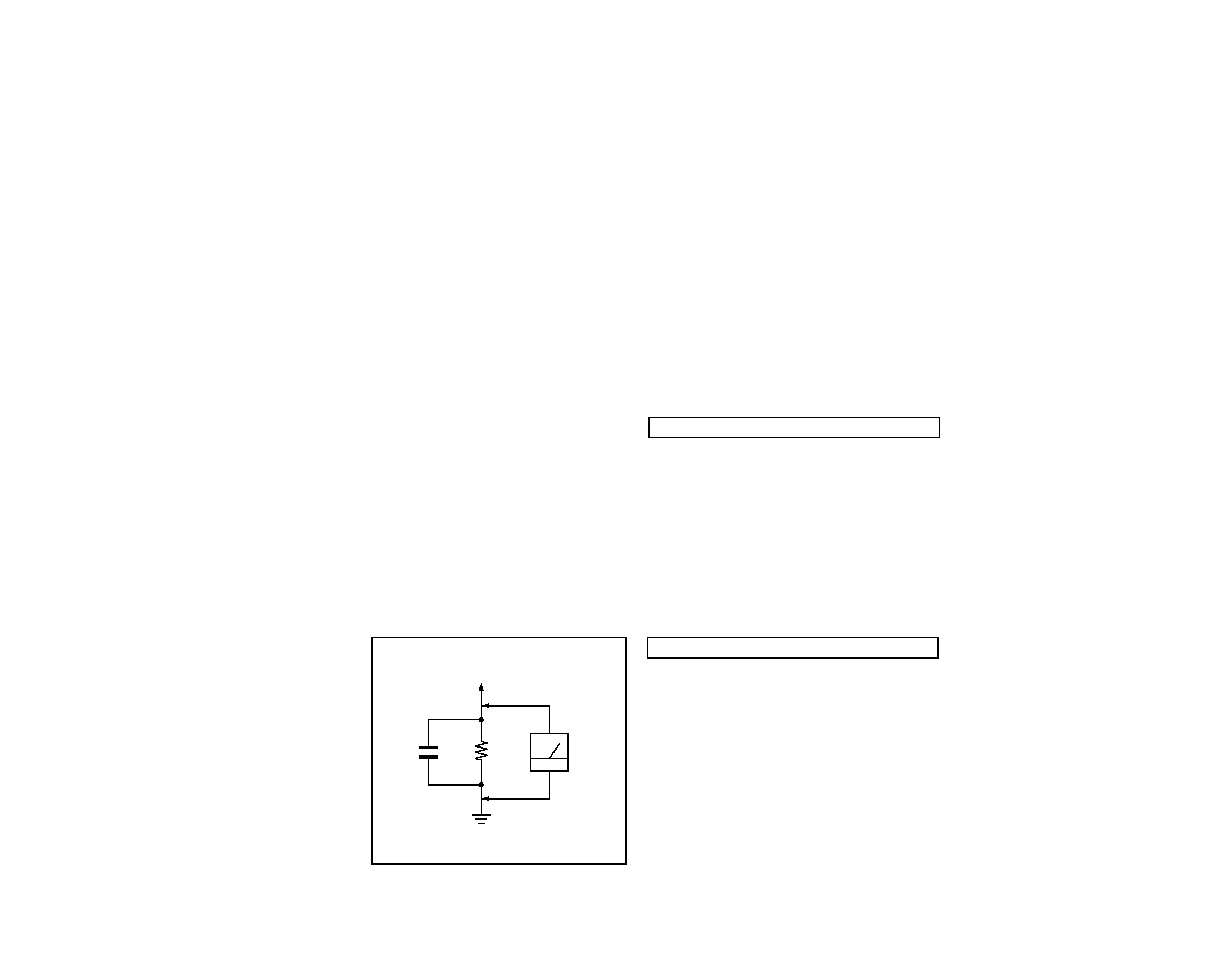
1.5 k
0.15 µF
AC
Voltmeter
(0.75 V)
To Exposed Metal
Parts on Set
Earth Ground
SAFETY CHECK-OUT
After correcting the original service problem, perform
the following safety checks before releasing the set to the
customer:
LEAKAGE TEST
The AC leakage from any exposed metal part to earth ground
and from all exposed metal parts to any exposed metal part having
a return to chassis, must not exceed 0.5 mA (500 microampere).
Leakage current can be measured by any one of three methods.
WARNING! !
WARNING! !
WARNING! !
WARNING! !
WARNING!!
NEVER TURN ON THE POWER IN A CONDITION IN WHICH THE
DEGAUSS COIL HAS BEEN REMOVED.
SAFETY-RELATED COMPONENT WARNING!!
COMPONENTS IDENTIFIED BY SHADING AND MARK
¡ ON
THE SCHEMATIC DIAGRAMS, EXPLODED VIEWS AND IN THE
PARTS LIST ARE CRITICAL FOR SAFE OPERATION. REPLACE
THESE COMPONENTS WITH SONY PARTS WHOSE PART
NUMBERS APPEAR AS SHOWN IN THIS MANUAL OR IN
SUPPLEMENTS PUBLISHED BY SONY. CIRCUIT ADJUSTMENTS
THAT ARE CRITICAL FOR SAFE OPERATION ARE IDENTIFIED
IN THIS MANUAL. FOLLOW THESE PROCEDURES WHENEVER
CRITICAL COMPONENTS ARE REPLACED OR IMPROPER
OPERATION IS SUSPECTED.
AVERTISSEMENT!!
NE JAMAIS METTRE SOUS TENSION QUAND LA BOBINE DE
DEMAGNETISATION EST ENLEVEE.
ATTENTION AUX COMPOSANTS RELATIFS A LA
SECURITE!!
LES COMPOSANTS IDENTIFIES PAR UNE TRAME ET PAR UNE
MARQUE
¡ SUR LES SCHEMAS DE PRINCIPE, LES VUES
EXPLOSEES ET LES LISTES DE PIECES SONT D'UNE
IMPORTANCE
CRITIQUE
POUR
LA
SECURITE
DU
FONCTIONNEMENT. NE LES REMPLACER QUE PAR DES
COMPOSANTS SONY DONT LE NUMERO DE PIECE EST
INDIQUE DANS LE PRESENT MANUEL OU DANS DES SUPPLE-
MENTS PUBLIES PAR SONY. LES REGLAGES DE CIRCUIT
DONT
L'IMPORTANCE
EST
CRITIQUE
POUR
LA
SECURITE DU FONCTIONNEMENT SONT IDENTIFIES DANS
LE PRESENT MANUEL. SUIVRE CES PROCEDURES LORS DE
CHAQUE REMPLACEMENT DE COMPOSANTS CRITIQUES, OU
LORSQU'UN MAUVAIS FONTIONNEMENT SUSPECTE.
1. Check the area of your repair for unsoldered or
poorly-soldered connections. Check the entire board
surface
for
solder
splashes
and
bridges.
2. Check the interboard wiring to ensure that no wires
are "pinched" or contact high-wattage resistors.
3. Check that all control knobs, shields, covers, ground
straps, and mounting hardware have been replaced.
Be absolutely certain that you have replaced all the
insulators.
4. Look for unauthorized replacement parts,
particularly transistors, that were installed during
a previous repair. Point them out to the customer
and recommend their replacement.
5. Look for parts which, though functioning, show
obvious signs of deterioration. Point them out to
the customer and recommend their replacement.
6. Check the line cords for cracks and abrasion.
Recommend the replacement of any such line cord
to the customer.
7. Check the B+ and HV to see if they are specified
values. Make sure your instruments are accurate;
be suspicious of your HV meter if sets always have
low HV.
8. Check the antenna terminals, metal trim,
"metallized" knobs, screws, and all other exposed
metal parts for AC Leakage. Check leakage as
described below.
1. A commercial leakage tester, such as the Simpson 229 or
RCA WT-540A. Follow the manufacturers' instructions to
use these instructions.
2. A battery-operated AC milliammeter. The Data Precision
245 digital multimeter is suitable for this job.
3. Measuring the voltage drop across a resistor by means of
a VOM or battery-operated AC voltmeter. The "limit"
indication is 0.75 V, so analog meters must have an accurate
low voltage scale. The Simpson's 250 and Sanwa
SH-63Trd are examples of passive VOMs that are suitable.
Nearly all battery operated digital multimeters that have a
2V AC range are suitable. (See Fig. A)

-- 4 --
CPD-220GS
TABLE OF CONTENTS
Section
Title
Page
1. GENERAL ................................................................................... 5
2. DISASSEMBLY
2-1. Cabinet Removal ............................................................13
2-2. Service Position .............................................................. 13
2-3. D,A and J Board Removal.............................................. 13
2-4. Picture Tube Removal ................................................... 14
3. SAFETY RELATED ADJUSTMENT................................. 15
4. ADJUSTMENTS ........................................................................ 16
5. DIAGRAMS
5-1. Block Diagram ................................................................19
5-2. Circuit Boards Location ................................................. 22
5-3. Schematic Diagrams and Printed Wiring Boards ...... 23
1. D Board - Schematic Diagram ................................. 23
2. A Board - Schematic Diagram ................................. 27
3. J Board - Schematic Diagram .................................. 30
5-4. Semiconductors ..............................................................31
6. EXPLODED VIEWS
6-1. Chassis ............................................................................ 33
6-2. Packing Materials .......................................................... 34
7. ELECTRICAL PARTS LIST ................................................ 35
--
5
--
CPD-220GS
SECTION 1
GENERAL
The instructions given here are partial abstracts from the Operating Instruction
Manual. The page numbers shown reflect those of the Operating Instruction Manual.
4
Getting Started
Warning on power connection
· Use an appropriate power cord for your local power
supply.
For the customers in the U.S.A.
If you do not use the appropriate cord, this monitor will
not conform to mandatory FCC standards.
Examples of plug types:
· Before disconnecting the power cord, wait at least 30
seconds after turning off the power to allow the static
electricity on the CRT display surface to discharge.
· After the power has been turned on, the CRT is
demagnetized (degaussed) for about 5 seconds. This
generates a strong magnetic field around the metal frame,
which may affect the data stored on magnetic tapes and
disks near the bezel. Place magnetic recording equipment,
tapes and disks away from this monitor.
The outlet should be installed near the equipment
and be easily accessible.
Precautions
Installation
· Prevent internal heat build-up by allowing adequate air
circulation. Do not place the monitor on surfaces (rugs,
blankets, etc.) or near materials (curtains, draperies) that
may block the ventilation holes.
· Do not install the monitor near heat sources such as
radiators or air ducts, or in a place subject to direct
sunlight, excessive dust, mechanical vibration or shock.
· Do not place the monitor near equipment which generates
magnetism, such as a transformer or high voltage power
lines.
Maintenance
· Clean the cabinet, panel and controls with a soft cloth
lightly moistened with a mild detergent solution. Do not
use any type of abrasive pad, scouring powder or solvent,
such as alcohol or benzine.
· Do not rub, touch, or tap the surface of the screen with
sharp or abrasive items such as a ballpoint pen or
screwdriver. This type of contact may result in a scratched
picture tube.
Transportation
When you transport this monitor for repair or shipment, use
the original carton and packing materials.
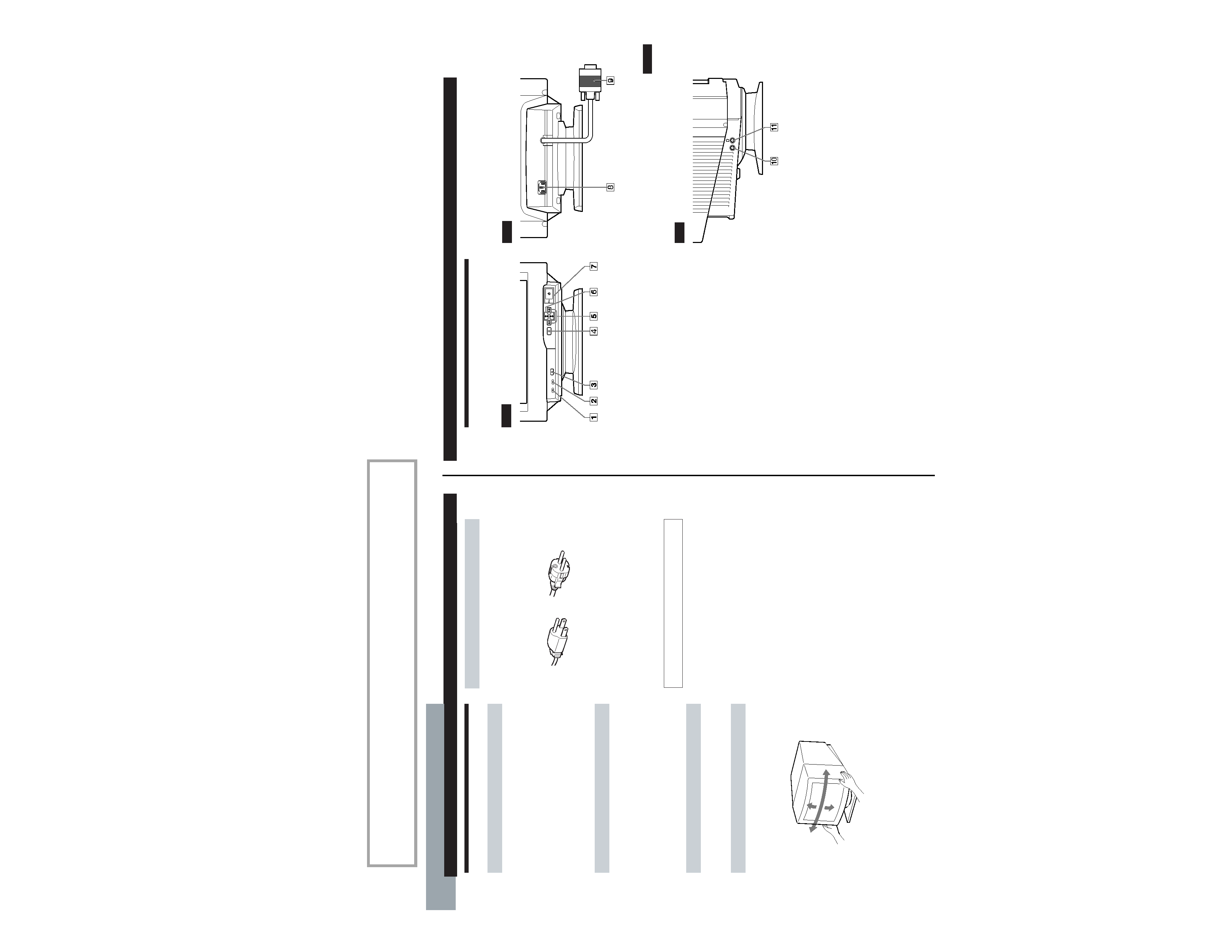
Use of the Tilt-Swivel
With the tilt-swivel, this monitor can be adjusted to the
desired angle within 180
° horizontally and 20° vertically.
To turn the monitor vertically and horizontally, hold it at
the bottom with both hands as illustrated below.
for 100 to 120 V AC
for 200 to 240 V AC
Getting started
90
°
90
°
15
°
5
°
5
Getting Started
F
EN
ES
C
Getting Started
Identifying Parts and Controls
See the pages in parentheses for further details.
Front
1 MUTING button (page 7)
Mutes the sound.
2 RESET button (page 15)
Resets the adjustments to the factory settings.
3 GPE button (page 16)
Selects the Graphic Picture Enhancement (GPE) mode.
4 MENU button (pages 7 -15, 17)
Displays the MENU OSD.
5 > (contrast) (?//) buttons (pages 7 15,
20)
Adjust the contrast.
Function as the (?//) buttons when adjusting other
items.
6 ¨ (brightness) (./>) buttons (pages 7
15)
Adjust the picture brightness.
Function as the (./>) buttons when adjusting other
items.
7 u (power) switch and indicator (pages 17,
20)
Turns the monitor on or off.
The indicator lights up in green when the monitor is
turned on, and lights up in orange when the monitor is
in power saving mode.
Rear
8 AC IN connector
Provides AC power to the monitor.
9 Video input connector (HD15)
Inputs RGB video signals and SYNC signals.
Side
!º AUDIO IN jack
Inputs audio signals when connected to the computer's
audio out jack.
!¡ 2 Headphones jack
Outputs audio signals to headphones (not supplied).
AUDIO
IN